2002 CHRYSLER TOWN AND COUNTRY tire pressure
[x] Cancel search: tire pressurePage 1978 of 2399

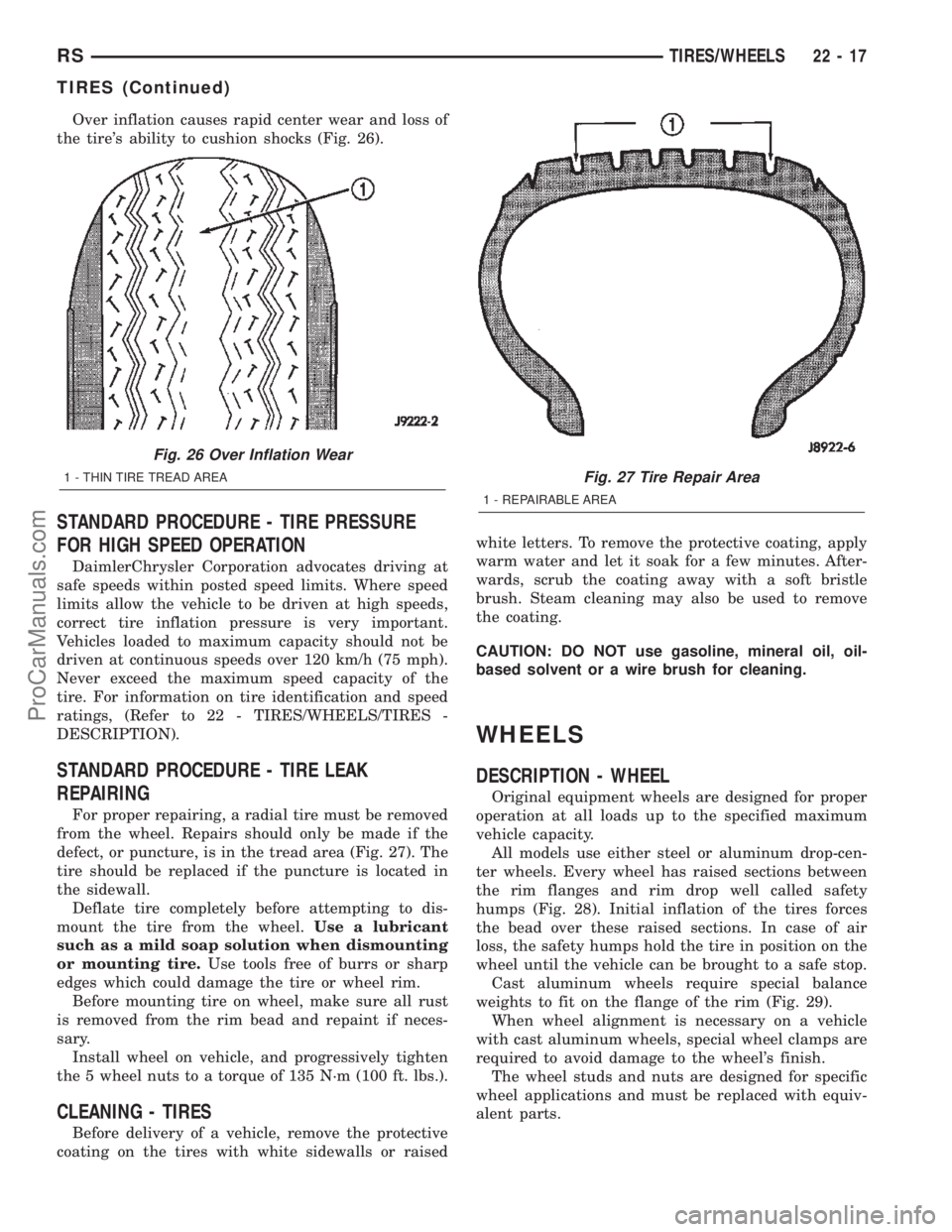
Over inflation causes rapid center wear and loss of
the tire's ability to cushion shocks (Fig. 26).
STANDARD PROCEDURE - TIRE PRESSURE
FOR HIGH SPEED OPERATION
DaimlerChrysler Corporation advocates driving at
safe speeds within posted speed limits. Where speed
limits allow the vehicle to be driven at high speeds,
correct tire inflation pressure is very important.
Vehicles loaded to maximum capacity should not be
driven at continuous speeds over 120 km/h (75 mph).
Never exceed the maximum speed capacity of the
tire. For information on tire identification and speed
ratings, (Refer to 22 - TIRES/WHEELS/TIRES -
DESCRIPTION).
STANDARD PROCEDURE - TIRE LEAK
REPAIRING
For proper repairing, a radial tire must be removed
from the wheel. Repairs should only be made if the
defect, or puncture, is in the tread area (Fig. 27). The
tire should be replaced if the puncture is located in
the sidewall.
Deflate tire completely before attempting to dis-
mount the tire from the wheel.Use a lubricant
such as a mild soap solution when dismounting
or mounting tire.Use tools free of burrs or sharp
edges which could damage the tire or wheel rim.
Before mounting tire on wheel, make sure all rust
is removed from the rim bead and repaint if neces-
sary.
Install wheel on vehicle, and progressively tighten
the 5 wheel nuts to a torque of 135 N´m (100 ft. lbs.).
CLEANING - TIRES
Before delivery of a vehicle, remove the protective
coating on the tires with white sidewalls or raisedwhite letters. To remove the protective coating, apply
warm water and let it soak for a few minutes. After-
wards, scrub the coating away with a soft bristle
brush. Steam cleaning may also be used to remove
the coating.
CAUTION: DO NOT use gasoline, mineral oil, oil-
based solvent or a wire brush for cleaning.
WHEELS
DESCRIPTION - WHEEL
Original equipment wheels are designed for proper
operation at all loads up to the specified maximum
vehicle capacity.
All models use either steel or aluminum drop-cen-
ter wheels. Every wheel has raised sections between
the rim flanges and rim drop well called safety
humps (Fig. 28). Initial inflation of the tires forces
the bead over these raised sections. In case of air
loss, the safety humps hold the tire in position on the
wheel until the vehicle can be brought to a safe stop.
Cast aluminum wheels require special balance
weights to fit on the flange of the rim (Fig. 29).
When wheel alignment is necessary on a vehicle
with cast aluminum wheels, special wheel clamps are
required to avoid damage to the wheel's finish.
The wheel studs and nuts are designed for specific
wheel applications and must be replaced with equiv-
alent parts.
Fig. 26 Over Inflation Wear
1 - THIN TIRE TREAD AREAFig. 27 Tire Repair Area
1 - REPAIRABLE AREA
RSTIRES/WHEELS22-17
TIRES (Continued)
ProCarManuals.com
Page 2305 of 2399

CAUTION: All tools, including the refrigerant recy-
cling equipment, the manifold gauge set, and test
hoses should be kept clean and dry. Keep the work
area clean. Contamination of the refrigerant system
through careless work habits must be avoided. The
refrigerant system will remain chemically stable as
long as pure, moisture-free R-134a refrigerant and
refrigerant oil is used. Dirt, moisture, or air can
upset this chemical stability. Operational troubles
or serious damage can occur if foreign material is
introduced to the refrigerant system.
COMPRESSOR
DESCRIPTION
The compressor used on this vehicle can be one of
two models, depending upon the air conditioning sys-
tem in the vehicle. All vehicles use the Nippondenso
10S20 compressor. This compressor use an aluminum
swash plate, teflon coated pistons and aluminum
sleeveless cylinder walls. This compressor includes
an integral high pressure relief valve. The compres-
sor is secured low in the right front corner of the
engine compartment to a mounting bracket on the
cylinder block (2.4L engine), or directly to the cylin-
der block (3.3L and 3.8L engines) is integral to the
compressor. This compressor cannot be repaired. If
faulty or damaged, the entire compressor must be
replaced. The compressor clutch, pulley, and clutch
coil are available for service replacement.
OPERATION
The compressor is driven by the engine through an
electric clutch, drive pulley and belt arrangement.
The compressor is lubricated by refrigerant oil that is
circulated throughout the refrigerant system with the
refrigerant. The compressor draws in low-pressure
refrigerant vapor from the evaporator through its
suction port. It then compresses the refrigerant into
a high-pressure, high-temperature refrigerant vapor.
The compressor pumps high-pressure refrigerant
vapor to the condenser through the compressor dis-
charge port. The mechanical high pressure relief
valve is designed to vent refrigerant from the system
to protect against damage to the compressor or other
system components, caused by condenser air flow
restrictions or an overcharge of refrigerant. The valve
only vents enough refrigerant to reduce the system
pressure, then re-seats itself. The valve opens at a
discharge pressure of 3445 to 4135 kPA (500 to 600
psi) or above, and closes when a minimum discharge
pressure of 2756 kPa (400 psi) is reached.
DIAGNOSIS AND TESTING - COMPRESSOR
NOISE DIAGNOSIS
Excessive noise while the air conditioning compres-
sor is operating can be caused by loose compressor
mounts, a loose compressor clutch, or high operating
pressures in the refrigerant system. Verify compres-
sor drive belt condition, proper compressor mounting,
correct refrigerant charge level, and compressor head
pressure before compressor repair is performed.
With the close tolerances within the compressor, it
is possible to experience a temporary lockup. The
longer the compressor is inactive, the more likely the
condition is to occur. This condition is the result of
normal refrigerant migration within the refrigerant
system caused by ambient temperature changes. The
refrigerant migration may wash the refrigerant oil
out of the compressor.
NOTE: Prior to a vehicle being removed from ser-
vice or stored for more than two weeks, the com-
pressor should be operated to ensure adequate
refrigerant oil distribution throughout the system
components. Turn on the air conditioner for a min-
imum of five minutes with outside air and the high-
est blower speed selected.
BELT NOISE
If the compressor drive belt slips at initial start-up,
it does not necessarily mean the compressor has
failed. The following procedure can be used to iden-
tify a compressor drive belt noise problem.
²Start the vehicle and run at idle.
²Turn the air conditioner On and listen for belt
squeal.
²If belt squeal is heard, turn the air conditioner
Off immediately.
If the belt squeal stops when the air conditioner is
turned Off, perform the following repair procedures.
(1) Using an appropriate sized oil filter wrench or
a strap wrench, grasp the outer diameter of the com-
pressor clutch hub. While facing the compressor,
rotate the hub clockwise, then counterclockwise. If
the hub rotates, proceed to the next step. If the hub
will not rotate, the compressor is internally damaged,
and must be replaced.
(2) Turn the hub clockwise five complete revolu-
tions and remove the tool.
(3) Start the vehicle and run at idle.
(4) Turn the air conditioner On. Observe the com-
pressor and the system for normal operation, noting
cooling performance and noise levels. Operate for five
minutes before turning the air conditioner Off. If
acceptable cooling performance is observed during
compressor operation, the compressor does not need
to be replaced.
24 - 62 PLUMBING - FRONTRS
PLUMBING - FRONT (Continued)
ProCarManuals.com
Page 2323 of 2399

HEATER HOSES - DIESEL
SUPPLEMENTAL HEATER -
BUX
REMOVAL
(1) Elevate vehicle on a lift taking note of the
exhaust tube flexible section.
(2) Drain cooling system(Refer to 7 - COOLING -
STANDARD PROCEDURE).
(3) Lower heater unit from vehicle(Refer to 24 -
HEATING & AIR CONDITIONING/CABIN HEAT-
ER/HEATER UNIT - REMOVAL).
NOTE: Complete removal of cabin heater from vehi-
cle is not required, lowering unit allows easier
access to coolant line clamps.
(4) Remove clamps from both flexible coolant line
ends.
(5) Remove both lines from vehicle.
NOTE: If either line is damaged it is recommended
that both flexible lines be replaced.
INSTALLATION
(1) Install both flexible coolant lines to the heater
unit and install clamps.
(2) Install flexible coolant lines to the coolant pipes
and install clamps.
(3) Install heater unit into vehicle(Refer to 24 -
HEATING & AIR CONDITIONING/CABIN HEAT-
ER/HEATER UNIT - INSTALLATION).
(4) Lower vehicle.
(5) Refill cooling system(Refer to 7 - COOLING -
STANDARD PROCEDURE).
(6) Verify operation of heater unit.
HEATER PIPES - DIESEL
SUPPLEMENTAL HEATER -
BUX
REMOVAL
CAUTION: Allow cooling system to cool completely
before removing radiator cap or draining cooling
system. Injury could result is system is opened
while system coolant is hot and under pressure.
NOTE: Steel heater lines from engine compartment
to heater unit are part of an assembly that includes
the air intake pipe. If the heater lines or air intake
pipe require removal or replacement the entire
assembly must be removed or replaced.
(1) Open hood.
(2) Drain the cooling system(Refer to 7 - COOL-
ING - STANDARD PROCEDURE).
(3) Remove clamps from both the EGR cooler and
the lower heater port. Separate hoses from the mat-
ing plumbing port. (Fig. 26).
(4) Remove retaining nut from heater line under
hood bracket.
(5) Elevate vehicle on a lift.
NOTE: When supporting vehicle care should be
taken not to damage the heater exhaust tube.
(6) Remove clamps from heater lines to the rubber
connection nearest the tubes. Separate the hoses
from the tube assembly leaving the rubber hose
attached to the supplemental heater.
(7) Remove heater unit intake pipe from heater-
(Refer to 24 - HEATING & AIR CONDITIONING/
CABIN HEATER/INLET HOSE - REMOVAL) (Fig.
27).
(8) Remove heater pipe assembly retaining screws
and remove assembly from vehicle.
24 - 80 PLUMBING - FRONTRS
ProCarManuals.com
Page 2349 of 2399

(18) Reconnect the suction line extension fitting to
the underbody suction line fitting. Tighten the fit-
tings to 23 N´m (17 ft. lbs.).
(19) Install a new tie strap just forward of the con-
nections between the underbody plumbing and the
engine compartment plumbing for the rear heater
and air conditioner.
(20) Lower the vehicle.
(21) Evacuate the refrigerant system. (Refer to 24
- HEATING & AIR CONDITIONING/PLUMBING -
FRONT/REFRIGERANT - STANDARD PROCE-
DURE - REFRIGERANT SYSTEM EVACUATE).
(22) Charge the refrigerant system. (Refer to 24 -
HEATING & AIR CONDITIONING/PLUMBING -
FRONT/REFRIGERANT - STANDARD PROCE-
DURE - REFRIGERANT SYSTEM CHARGE).
UNDERBODY LINES
DESCRIPTION
The rear heater-A/C unit plumbing is used only on
models with the optional rear heater-A/C unit. The
formed metal rear heater-A/C unit suction line, liquid
line, and heater lines are available for separate ser-
vice replacement. The molded and straight heater
hoses used on the rear heater-A/C unit can be ser-
viced in the vehicle. Refer to Group 7 - Cooling Sys-
tem for the heater hose service procedures.
OPERATION
The rear heater and A/C lines are all serviced as
individual pieces. When disconnecting any line or
block ensure that the area around it is clean of any
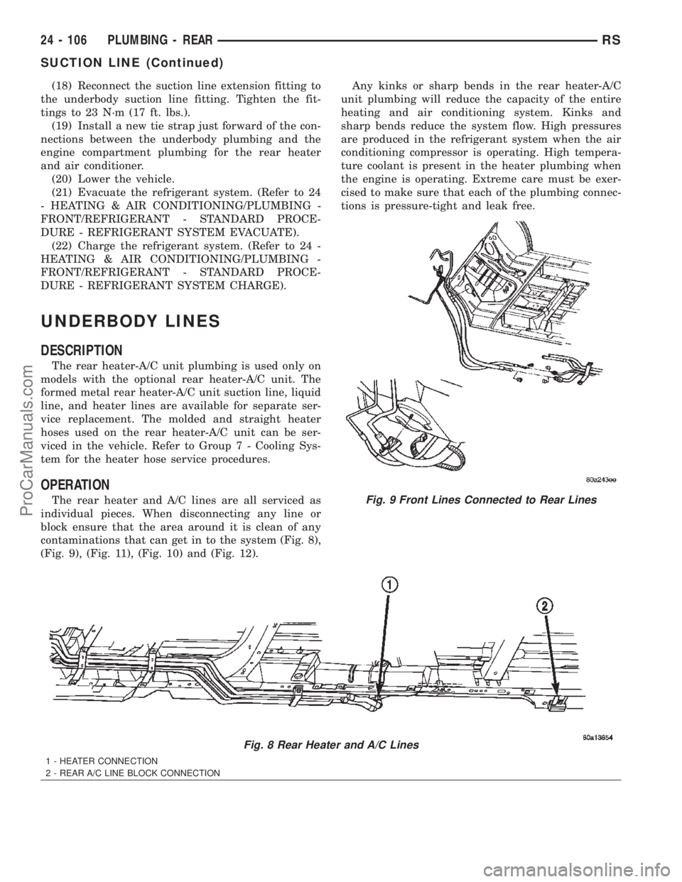
contaminations that can get in to the system (Fig. 8),
(Fig. 9), (Fig. 11), (Fig. 10) and (Fig. 12).Any kinks or sharp bends in the rear heater-A/C
unit plumbing will reduce the capacity of the entire
heating and air conditioning system. Kinks and
sharp bends reduce the system flow. High pressures
are produced in the refrigerant system when the air
conditioning compressor is operating. High tempera-
ture coolant is present in the heater plumbing when
the engine is operating. Extreme care must be exer-
cised to make sure that each of the plumbing connec-
tions is pressure-tight and leak free.
Fig. 8 Rear Heater and A/C Lines
1 - HEATER CONNECTION
2 - REAR A/C LINE BLOCK CONNECTION
Fig. 9 Front Lines Connected to Rear Lines
24 - 106 PLUMBING - REARRS
SUCTION LINE (Continued)
ProCarManuals.com