2002 CHRYSLER TOWN AND COUNTRY engine oil cooler
[x] Cancel search: engine oil coolerPage 1381 of 2399
(13) Remove rocker arm and lifter assemblies from
cylinder head.
(14) Remove cylinder head cover/intake manifold
gasket from cylinder head.
(15) Disconnect glow plug and engine coolant tem-
perture electrical connectors.
(16) Remove coolant recovery pressure container
(Refer to 7 - COOLING/ENGINE/COOLANT RECOV-
ERY PRESS CONTAINER - REMOVAL).
(17) Remove thermostat housing to upper radiator
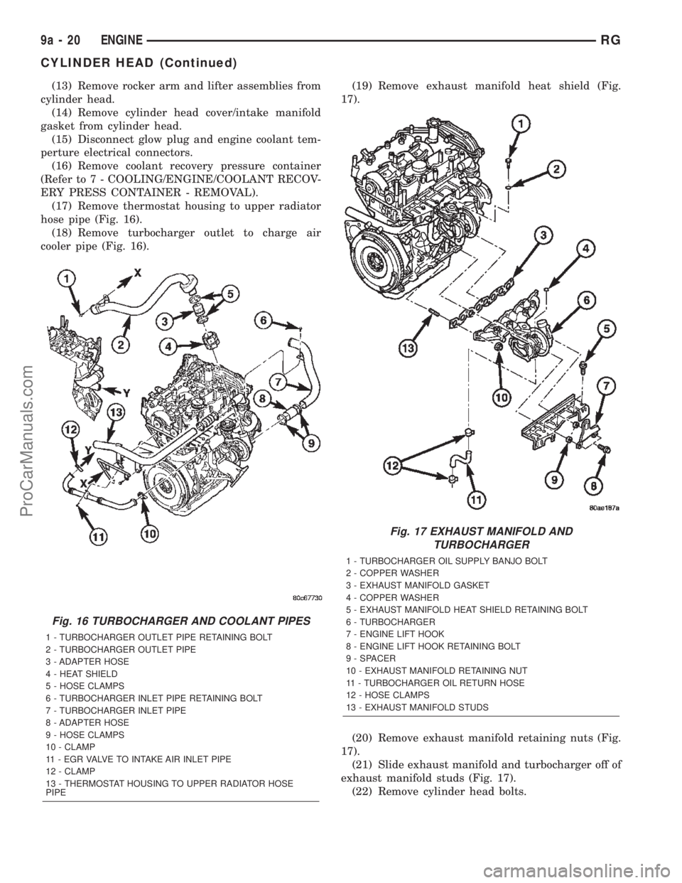
hose pipe (Fig. 16).
(18) Remove turbocharger outlet to charge air
cooler pipe (Fig. 16).(19) Remove exhaust manifold heat shield (Fig.
17).
(20) Remove exhaust manifold retaining nuts (Fig.
17).
(21) Slide exhaust manifold and turbocharger off of
exhaust manifold studs (Fig. 17).
(22) Remove cylinder head bolts.
Fig. 16 TURBOCHARGER AND COOLANT PIPES
1 - TURBOCHARGER OUTLET PIPE RETAINING BOLT
2 - TURBOCHARGER OUTLET PIPE
3 - ADAPTER HOSE
4 - HEAT SHIELD
5 - HOSE CLAMPS
6 - TURBOCHARGER INLET PIPE RETAINING BOLT
7 - TURBOCHARGER INLET PIPE
8 - ADAPTER HOSE
9 - HOSE CLAMPS
10 - CLAMP
11 - EGR VALVE TO INTAKE AIR INLET PIPE
12 - CLAMP
13 - THERMOSTAT HOUSING TO UPPER RADIATOR HOSE
PIPE
Fig. 17 EXHAUST MANIFOLD AND
TURBOCHARGER
1 - TURBOCHARGER OIL SUPPLY BANJO BOLT
2 - COPPER WASHER
3 - EXHAUST MANIFOLD GASKET
4 - COPPER WASHER
5 - EXHAUST MANIFOLD HEAT SHIELD RETAINING BOLT
6 - TURBOCHARGER
7 - ENGINE LIFT HOOK
8 - ENGINE LIFT HOOK RETAINING BOLT
9 - SPACER
10 - EXHAUST MANIFOLD RETAINING NUT
11 - TURBOCHARGER OIL RETURN HOSE
12 - HOSE CLAMPS
13 - EXHAUST MANIFOLD STUDS
9a - 20 ENGINERG
CYLINDER HEAD (Continued)
ProCarManuals.com
Page 1411 of 2399

(4) Using special tool VM.1059, push oil pressure
relief valve cap in untill flush with engine block (Fig.
77).
(5) Install oil pan (Refer to 9 - ENGINE/LUBRI-
CATION/OIL PAN - INSTALLATION).
OIL COOLER & LINES
REMOVAL
(1) Drain cooling system (Refer to 7 - COOLING/
ENGINE/COOLANT - STANDARD PROCEDURE).
(2) Raise vehicle on hoist.
(3) Remove oil filter cap and filter (Refer to 9 -
ENGINE/LUBRICATION/OIL FILTER - REMOVAL).
(4) Remove oil filter housing retaining nut and
housing (Fig. 78).
(5) Disconnect coolant hoses at cooler (Fig. 79).
(6) Remove oil cooler retaining bolt at engine block
(Fig. 79).
(7) Remove oil cooler retaining stud and remove oil
cooler from engine block (Fig. 79).
INSTALLATION
(1) Clean oil cooler and engine block sealing sur-
faces.
Fig. 77 OIL PRESSURE RELIEF VALVE
INSTALLATION
1 - VM.1059
2 - OIL PRESSURE RELIEF VALVE
3 - ENGINE BLOCK
4 - OIL PUMP
Fig. 78 OIL FILTER HOUSING RETAINING NUT
1 - OIL FILTER HOUSING
2 - OIL FILTER HOUSING RETAINING NUT
3 - OIL COOLER
Fig. 79 WATER PUMP AND OIL COOLER
ASSEMBLIES
1 - WATER PUMP HOUSING STUDS
2 - WATER PUMP
3 - RETAINING NUTS
4 - OIL COOLER RETAINING STUD
5 - OIL COOLER TO ENGINE BLOCK RETAINING BOLT
6 - OIL COOLER COOLANT HOSE
7 - ENGINE BLOCK
9a - 50 ENGINERG
OIL PRESSURE RELIEF VALVE (Continued)
ProCarManuals.com
Page 1412 of 2399
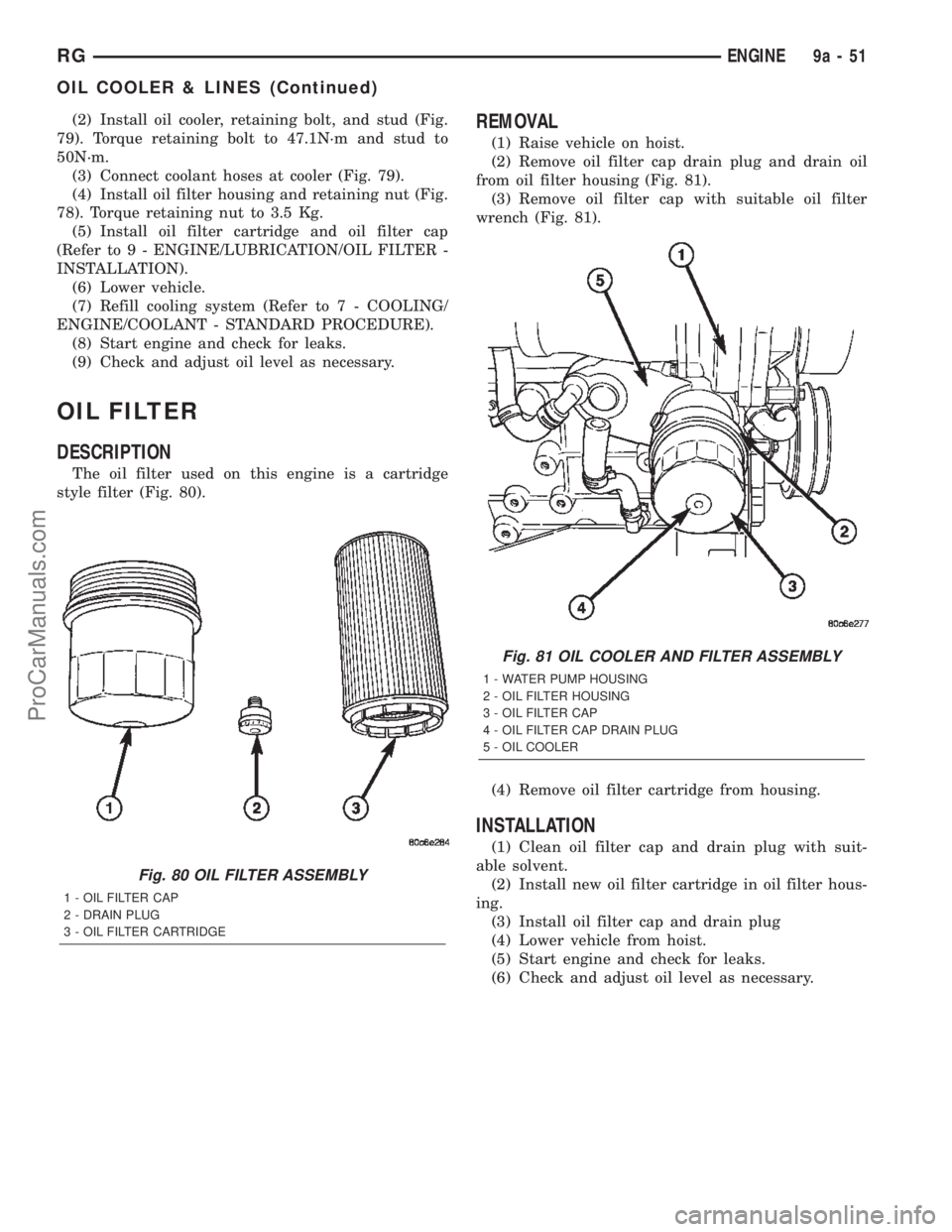
(2) Install oil cooler, retaining bolt, and stud (Fig.
79). Torque retaining bolt to 47.1N´m and stud to
50N´m.
(3) Connect coolant hoses at cooler (Fig. 79).
(4) Install oil filter housing and retaining nut (Fig.
78). Torque retaining nut to 3.5 Kg.
(5) Install oil filter cartridge and oil filter cap
(Refer to 9 - ENGINE/LUBRICATION/OIL FILTER -
INSTALLATION).
(6) Lower vehicle.
(7) Refill cooling system (Refer to 7 - COOLING/
ENGINE/COOLANT - STANDARD PROCEDURE).
(8) Start engine and check for leaks.
(9) Check and adjust oil level as necessary.
OIL FILTER
DESCRIPTION
The oil filter used on this engine is a cartridge
style filter (Fig. 80).
REMOVAL
(1) Raise vehicle on hoist.
(2) Remove oil filter cap drain plug and drain oil
from oil filter housing (Fig. 81).
(3) Remove oil filter cap with suitable oil filter
wrench (Fig. 81).
(4) Remove oil filter cartridge from housing.
INSTALLATION
(1) Clean oil filter cap and drain plug with suit-
able solvent.
(2) Install new oil filter cartridge in oil filter hous-
ing.
(3) Install oil filter cap and drain plug
(4) Lower vehicle from hoist.
(5) Start engine and check for leaks.
(6) Check and adjust oil level as necessary.
Fig. 80 OIL FILTER ASSEMBLY
1 - OIL FILTER CAP
2 - DRAIN PLUG
3 - OIL FILTER CARTRIDGE
Fig. 81 OIL COOLER AND FILTER ASSEMBLY
1 - WATER PUMP HOUSING
2 - OIL FILTER HOUSING
3 - OIL FILTER CAP
4 - OIL FILTER CAP DRAIN PLUG
5 - OIL COOLER
RGENGINE9a-51
OIL COOLER & LINES (Continued)
ProCarManuals.com
Page 1435 of 2399
TURBOCHARGER SYSTEM
DESCRIPTION
CAUTION: The turbocharger is a performance part
and must not be tampered with. The wastegate
bracket is an integral part of the turbocharger. Tam-
pering with the wastegate components can reduce
durability by increasing cylinder pressure and ther-
mal loading due to incorrect inlet and exhaust man-
ifold pressure. Poor fuel economy and failure to
meet regulatory emissions laws may result. Increas-
ing the turbocharger boost WILL NOT increase
engine power.
The turbocharger is an exhaust-driven super-
charger which increases the pressure and density of
the air entering the engine. With the increase of air
entering the engine, more fuel can be injected into
the cylinders, which creates more power during com-
bustion.
The turbocharger assembly consists of four (4)
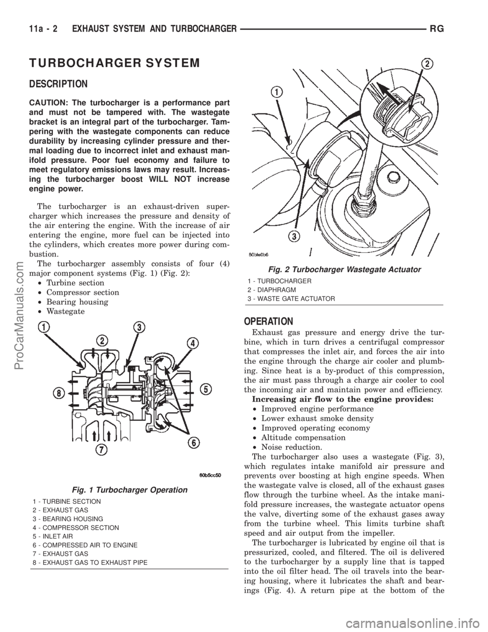
major component systems (Fig. 1) (Fig. 2):
²Turbine section
²Compressor section
²Bearing housing
²Wastegate
OPERATION
Exhaust gas pressure and energy drive the tur-
bine, which in turn drives a centrifugal compressor
that compresses the inlet air, and forces the air into
the engine through the charge air cooler and plumb-
ing. Since heat is a by-product of this compression,
the air must pass through a charge air cooler to cool
the incoming air and maintain power and efficiency.
Increasing air flow to the engine provides:
²Improved engine performance
²Lower exhaust smoke density
²Improved operating economy
²Altitude compensation
²Noise reduction.
The turbocharger also uses a wastegate (Fig. 3),
which regulates intake manifold air pressure and
prevents over boosting at high engine speeds. When
the wastegate valve is closed, all of the exhaust gases
flow through the turbine wheel. As the intake mani-
fold pressure increases, the wastegate actuator opens
the valve, diverting some of the exhaust gases away
from the turbine wheel. This limits turbine shaft
speed and air output from the impeller.
The turbocharger is lubricated by engine oil that is
pressurized, cooled, and filtered. The oil is delivered
to the turbocharger by a supply line that is tapped
into the oil filter head. The oil travels into the bear-
ing housing, where it lubricates the shaft and bear-
ings (Fig. 4). A return pipe at the bottom of the
Fig. 1 Turbocharger Operation
1 - TURBINE SECTION
2 - EXHAUST GAS
3 - BEARING HOUSING
4 - COMPRESSOR SECTION
5 - INLET AIR
6 - COMPRESSED AIR TO ENGINE
7 - EXHAUST GAS
8 - EXHAUST GAS TO EXHAUST PIPE
Fig. 2 Turbocharger Wastegate Actuator
1 - TURBOCHARGER
2 - DIAPHRAGM
3 - WASTE GATE ACTUATOR
11a - 2 EXHAUST SYSTEM AND TURBOCHARGERRG
ProCarManuals.com
Page 1552 of 2399
(10) Tighten hose tube nut at power steering gear
port to 31 N´m (275 in. lbs.) torque.
(11) Install front emissions vapor canister. (Refer
to 25 - EMISSIONS CONTROL/EVAPORATIVE
EMISSIONS/VAPOR CANISTER - INSTALLATION)
(12) Lower vehicle.
(13) Fill and bleed the power steering system
using the Power Steering Pump Initial Operation
Procedure. (Refer to 19 - STEERING/PUMP - STAN-
DARD PROCEDURE)
(14) Inspect system for leaks.
HOSE - POWER STEERING
RETURN
REMOVAL
REMOVAL - 2.4L ENGINE
NOTE: Before proceeding, review all WARNINGS
and CAUTIONS. (Refer to 19 - STEERING/PUMP -
WARNING)(Refer to 19 - STEERING/PUMP - CAU-
TION)
(1) Remove cap from power steering fluid reser-
voir.
(2) Using a siphon pump, remove as much power
steering fluid as possible from power steering fluid
reservoir.
(3) Raise vehicle. (Refer to LUBRICATION &
MAINTENANCE/HOISTING - STANDARD PROCE-
DURE)
(4) Remove front emissions vapor canister. (Refer
to 25 - EMISSIONS CONTROL/EVAPORATIVE
EMISSIONS/VAPOR CANISTER - REMOVAL)
(5) Place an oil drain pan under vehicle to catch
power steering fluid.
(6) Cut tie-strap securing insulating heat sleeve to
power steering fluid return hose near power steering
pump. Pull back heat sleeve to expose hose clamp.
(7) Remove clamp, then return hose from power
steering pump (Fig. 19).
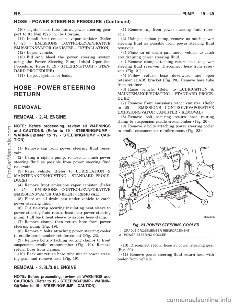
(8) Remove 2 bolts attaching power steering cooler
to cradle crossmember reinforcement (Fig. 23).
(9) Remove bolts attaching routing clamps to front
suspension cradle crossmember (Fig. 19). Remove
return hose from clamps.
(10) Back out return hose tube nut at power steer-
ing gear and remove hose (Fig. 19).
REMOVAL - 3.3L/3.8L ENGINE
NOTE:Before proceeding, review all WARNINGS and
CAUTIONS. (Refer to 19 - STEERING/PUMP - WARNIN-
G)(Refer to 19 - STEERING/PUMP - CAUTION)
(1) Remove cap from power steering fluid reser-
voir.
(2) Using a siphon pump, remove as much power
steering fluid as possible from power steering fluid
reservoir.
(3) Place an oil drain pan under vehicle to catch
any draining power steering fluid.
(4) Remove clamp attaching return hose to power
steering fluid reservoir. Disconnect hose from reser-
voir (Fig. 21).
(5) Follow return hose downward and open
retainer at ABS bracket (Fig. 20). Remove hose tube
from retainer.
(6) Raise vehicle. (Refer to LUBRICATION &
MAINTENANCE/HOISTING - STANDARD PROCE-
DURE)
(7) Remove front emissions vapor canister. (Refer
to 25 - EMISSIONS CONTROL/EVAPORATIVE
EMISSIONS/VAPOR CANISTER - REMOVAL)
(8) Remove bolt securing return hose routing
clamp to suspension cradle crossmember (Fig. 20).
(9) Remove 2 bolts attaching power steering cooler
to cradle crossmember reinforcement (Fig. 23).
(10) Disconnect return hose at power steering gear
(Fig. 20).
(11) Remove power steering fluid return hose with
cooler from vehicle.
Fig. 23 POWER STEERING COOLER
1 - CRADLE CROSSMEMBER REINFORCEMENT
2 - POWER STEERING COOLER
RSPUMP19-49
HOSE - POWER STEERING PRESSURE (Continued)
ProCarManuals.com
Page 1579 of 2399
ASSEMBLY...........................115
SHIFT INTERLOCK SOLENOID
DESCRIPTION........................115
OPERATION..........................115
DIAGNOSIS AND TESTING - BRAKE/
TRANSMISSION SHIFT INTERLOCK
SOLENOID..........................117
REMOVAL............................117
INSTALLATION........................118
SOLENOID - TCC
DESCRIPTION........................119
OPERATION..........................119
REMOVAL............................119
INSTALLATION........................120
THROTTLE VALVE CABLE
REMOVAL............................120
INSTALLATION........................121
ADJUSTMENTS
THROTTLE VALVE LINKAGE
ADJUSTMENT.......................122
TORQUE CONVERTER
DESCRIPTION........................122
OPERATION..........................126
REMOVAL............................127
INSTALLATION........................127
TRANSFER SYSTEM - OUTPUT SHAFT/GEAR/
BEARING
REMOVAL............................128INSTALLATION........................131
ADJUSTMENTS
ADJUSTMENT - OUTPUT SHAFT BEARING . 135
TRANSFER SYSTEM - TRANSFER SHAFT/
GEAR/BEARING
REMOVAL............................137
INSTALLATION........................141
ADJUSTMENTS
ADJUSTMENT - TRANSFER SHAFT
BEARING...........................145
VALVE BODY
REMOVAL............................146
DISASSEMBLY........................148
CLEANING...........................154
INSPECTION.........................155
ASSEMBLY...........................155
INSTALLATION........................158
ADJUSTMENTS
HYDRAULIC CONTROL PRESSURE
ADJUSTMENTS......................160
VEHICLE SPEED SENSOR/PINION GEAR
REMOVAL............................160
INSTALLATION........................160
31TH AUTOMATIC
TRANSAXLE
DESCRIPTION
This transaxle combines torque converter, three
speed transmission, final drive gearing, and differen-
tial into a front wheel drive system.
Within this transaxle, there are three primary
areas:
(1) Main center line plus valve body.
(2) Transfer shaft center line (includes governor
and parking sprag).
(3) Differential center line.
Center distances between the main rotating parts
in these three areas are held precise to maintain a
low noise level.
The torque converter, transaxle area, and differen-
tial are housed in an integral aluminum die casting.
The differential oil sump is common with the
transaxle sump. Separate filling of the differen-
tial is NOT necessary.
The torque converter is attached to the crankshaft
through a flexible driving plate. Cooling of the con-
verter is accomplished by circulating the transaxle
fluid through a remote cooler. There are two types of
coolers used. An oil-to-water type cooler located in
the radiator side tank and/or an oil-to-air heatexchanger. The torque converter assembly is a sealed
unit that cannot be disassembled.
The transaxle fluid is filtered by an internal filter
attached to the lower side of the valve body assembly.
Engine torque is transmitted to the torque con-
verter and then through the input shaft to multiple-
disc clutches in the transaxle. The power flow
depends on the application of the clutches and bands.
Refer to Elements in Use Chart in Diagnosis and
Tests section.
The transaxle consists of:
²Two multiple-disc clutches
²An overrunning clutch
²Two servos
²A hydraulic accumulator
²Two bands
²Two planetary gear sets
This provides three forward ratios and a reverse
ratio. The common sun gear of the planetary gear
sets is connected to the front clutch by a driving
shell. The driving shell is splined to the sun gear and
front clutch retainer. The hydraulic system consists
of an oil pump and a single valve body which con-
tains all of the valves except the governor valves.
The transaxle sump and differential sump are both
vented through the dipstick. Output torque from the
main center line is delivered through helical gears to
the transfer shaft. This gear set is a factor in the
transaxle final drive (axle) ratio. The shaft also car-
21 - 22 31TH AUTOMATIC TRANSAXLERS
ProCarManuals.com
Page 1586 of 2399
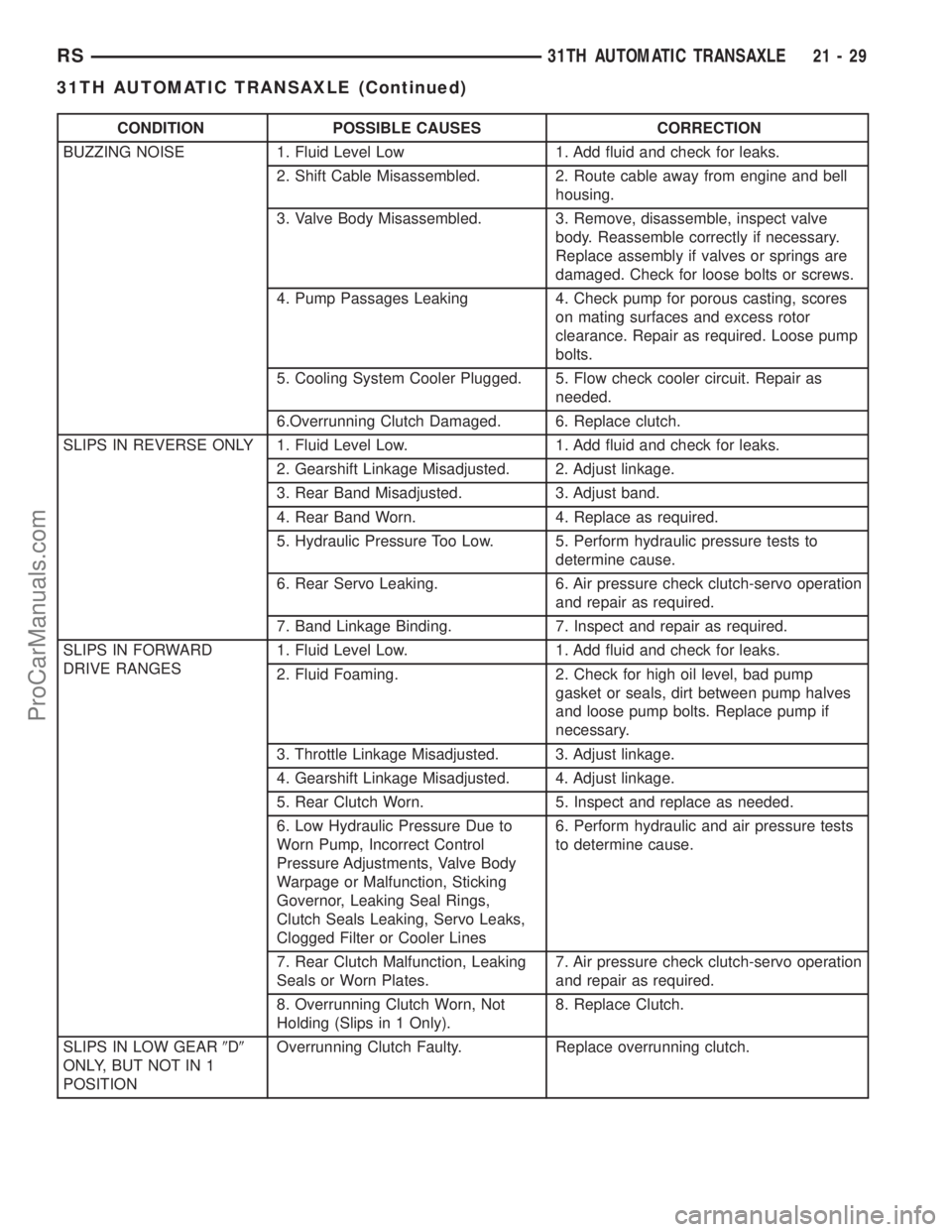
CONDITION POSSIBLE CAUSES CORRECTION
BUZZING NOISE 1. Fluid Level Low 1. Add fluid and check for leaks.
2. Shift Cable Misassembled. 2. Route cable away from engine and bell
housing.
3. Valve Body Misassembled. 3. Remove, disassemble, inspect valve
body. Reassemble correctly if necessary.
Replace assembly if valves or springs are
damaged. Check for loose bolts or screws.
4. Pump Passages Leaking 4. Check pump for porous casting, scores
on mating surfaces and excess rotor
clearance. Repair as required. Loose pump
bolts.
5. Cooling System Cooler Plugged. 5. Flow check cooler circuit. Repair as
needed.
6.Overrunning Clutch Damaged. 6. Replace clutch.
SLIPS IN REVERSE ONLY 1. Fluid Level Low. 1. Add fluid and check for leaks.
2. Gearshift Linkage Misadjusted. 2. Adjust linkage.
3. Rear Band Misadjusted. 3. Adjust band.
4. Rear Band Worn. 4. Replace as required.
5. Hydraulic Pressure Too Low. 5. Perform hydraulic pressure tests to
determine cause.
6. Rear Servo Leaking. 6. Air pressure check clutch-servo operation
and repair as required.
7. Band Linkage Binding. 7. Inspect and repair as required.
SLIPS IN FORWARD
DRIVE RANGES1. Fluid Level Low. 1. Add fluid and check for leaks.
2. Fluid Foaming. 2. Check for high oil level, bad pump
gasket or seals, dirt between pump halves
and loose pump bolts. Replace pump if
necessary.
3. Throttle Linkage Misadjusted. 3. Adjust linkage.
4. Gearshift Linkage Misadjusted. 4. Adjust linkage.
5. Rear Clutch Worn. 5. Inspect and replace as needed.
6. Low Hydraulic Pressure Due to
Worn Pump, Incorrect Control
Pressure Adjustments, Valve Body
Warpage or Malfunction, Sticking
Governor, Leaking Seal Rings,
Clutch Seals Leaking, Servo Leaks,
Clogged Filter or Cooler Lines6. Perform hydraulic and air pressure tests
to determine cause.
7. Rear Clutch Malfunction, Leaking
Seals or Worn Plates.7. Air pressure check clutch-servo operation
and repair as required.
8. Overrunning Clutch Worn, Not
Holding (Slips in 1 Only).8. Replace Clutch.
SLIPS IN LOW GEAR9D9
ONLY, BUT NOT IN 1
POSITIONOverrunning Clutch Faulty. Replace overrunning clutch.
RS31TH AUTOMATIC TRANSAXLE21-29
31TH AUTOMATIC TRANSAXLE (Continued)
ProCarManuals.com
Page 1596 of 2399
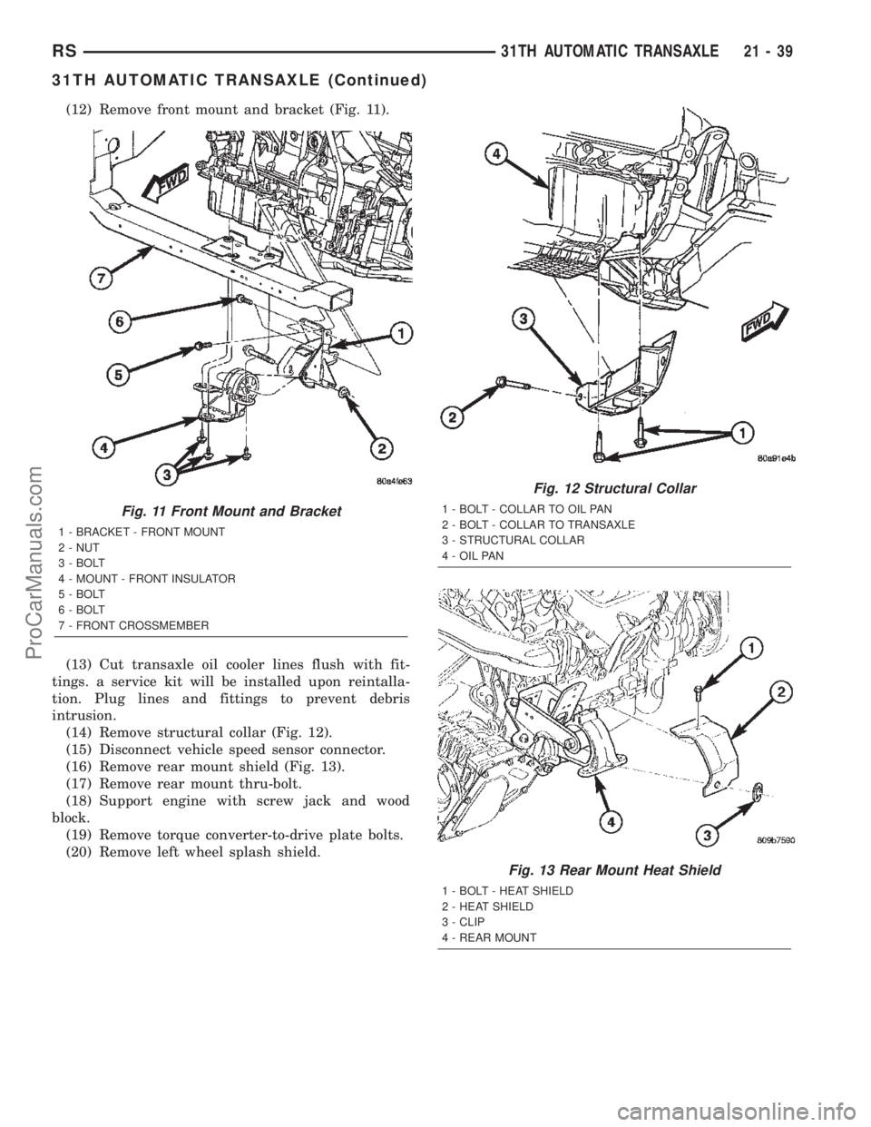
(12) Remove front mount and bracket (Fig. 11).
(13) Cut transaxle oil cooler lines flush with fit-
tings. a service kit will be installed upon reintalla-
tion. Plug lines and fittings to prevent debris
intrusion.
(14) Remove structural collar (Fig. 12).
(15) Disconnect vehicle speed sensor connector.
(16) Remove rear mount shield (Fig. 13).
(17) Remove rear mount thru-bolt.
(18) Support engine with screw jack and wood
block.
(19) Remove torque converter-to-drive plate bolts.
(20) Remove left wheel splash shield.
Fig. 11 Front Mount and Bracket
1 - BRACKET - FRONT MOUNT
2 - NUT
3 - BOLT
4 - MOUNT - FRONT INSULATOR
5 - BOLT
6 - BOLT
7 - FRONT CROSSMEMBER
Fig. 12 Structural Collar
1 - BOLT - COLLAR TO OIL PAN
2 - BOLT - COLLAR TO TRANSAXLE
3 - STRUCTURAL COLLAR
4 - OIL PAN
Fig. 13 Rear Mount Heat Shield
1 - BOLT - HEAT SHIELD
2 - HEAT SHIELD
3 - CLIP
4 - REAR MOUNT
RS31TH AUTOMATIC TRANSAXLE21-39
31TH AUTOMATIC TRANSAXLE (Continued)
ProCarManuals.com