2002 CHRYSLER TOWN AND COUNTRY brakes
[x] Cancel search: brakesPage 134 of 2399

RED BRAKE WARNING INDICATOR LAMP
CONDITION POSSIBLE CAUSES CORRECTION
RED BRAKE WARNING
LAMP ON1. Parking brake lever not fully
released.1. Release parking brake lever.
2. Parking brake warning lamp
switch on parking brake lever.2. Inspect and replace switch as necessary.
3. Brake fluid level low in reservoir. 3. Fill reservoir. Check entire system for
leaks. Repair or replace as required.
4. Brake fluid level switch. 4. Disconnect switch wiring connector. If
lamp goes out, replace switch.
5. Mechanical instrument cluster
(MIC) problem.5. Refer to appropriate Diagnostic
information.
6. Amber ABS Warning Indicator
Lamp also illuminated.6. Refer to appropriate Diagnostic
information.
BRAKE NOISE
CONDITION POSSIBLE CAUSES CORRECTION
CLICK OR SQUAWK ON
PEDAL APPLICATION1. Brake lamp switch. 1. Replace switch.
2. Brake Transmission Shift Interlock
Linkage.2. Lubricate BTSI linkage.
3. Pedal pivot bushings 3. Lubricate pivot bushings. Replace if
necessary.
DISC BRAKE CHIRP 1. Excessive brake rotor runout. 1. Follow brake rotor diagnosis and testing.
Correct as necessary.
2. Lack of lubricant on brake caliper
slides.2. Lubricate brake caliper slides.
3. Caliper/shoes not fully seated. 3. Reseat caliper/shoes.
DISC BRAKE RATTLE OR
CLUNK1. Broken or missing anti-rattle
spring clips on shoes.1. Replace brake shoes.
2. Caliper guide pins/bolts loose. 2. Tighten guide pins/bolts.
DISC BRAKE SQUEAK AT
LOW SPEED (WHILE
APPLYING LIGHT BRAKE
PEDAL EFFORT)1. Brake shoe linings. 1. Replace brake shoes.
DRUM BRAKE CHIRP 1. Lack of lubricant on brake shoe
support plate where shoes ride.1. Lubricate shoe contact areas on brake
shoe support plates.
DRUM BRAKE CLUNK 1. Drum(s) have threaded machined
braking surface.1. Replace brake drums as necessary.
DRUM BRAKE HOWL OR
MOAN1. Lack of lubricant on brake shoe
support plate where shoes ride and
at the anchor.1. Lubricate shoe contact areas on brake
shoe support plates and at the anchor.
2. Rear brake shoes. 2. Replace rear brake shoes.
DRUM BRAKE SCRAPING
OR WHIRRING1. ABS wheel speed sensor or tone
wheel.1. Inspect, correct or replace faulty
component(s).
RSBRAKES - BASE5-5
BRAKES - BASE (Continued)
ProCarManuals.com
Page 135 of 2399

CONDITION POSSIBLE CAUSES CORRECTION
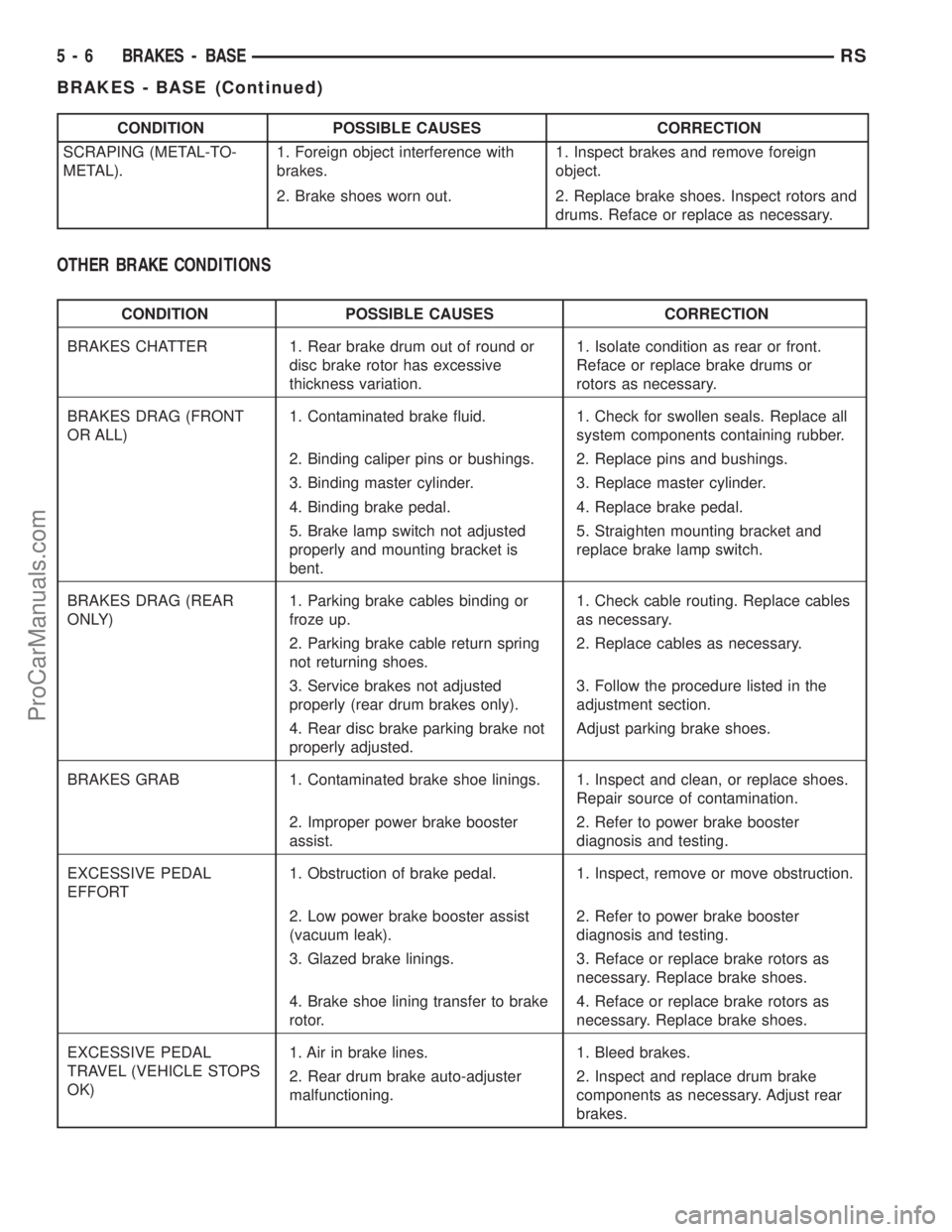
SCRAPING (METAL-TO-
METAL).1. Foreign object interference with
brakes.1. Inspect brakes and remove foreign
object.
2. Brake shoes worn out. 2. Replace brake shoes. Inspect rotors and
drums. Reface or replace as necessary.
OTHER BRAKE CONDITIONS
CONDITION POSSIBLE CAUSES CORRECTION
BRAKES CHATTER 1. Rear brake drum out of round or
disc brake rotor has excessive
thickness variation.1. Isolate condition as rear or front.
Reface or replace brake drums or
rotors as necessary.
BRAKES DRAG (FRONT
OR ALL)1. Contaminated brake fluid. 1. Check for swollen seals. Replace all
system components containing rubber.
2. Binding caliper pins or bushings. 2. Replace pins and bushings.
3. Binding master cylinder. 3. Replace master cylinder.
4. Binding brake pedal. 4. Replace brake pedal.
5. Brake lamp switch not adjusted
properly and mounting bracket is
bent.5. Straighten mounting bracket and
replace brake lamp switch.
BRAKES DRAG (REAR
ONLY)1. Parking brake cables binding or
froze up.1. Check cable routing. Replace cables
as necessary.
2. Parking brake cable return spring
not returning shoes.2. Replace cables as necessary.
3. Service brakes not adjusted
properly (rear drum brakes only).3. Follow the procedure listed in the
adjustment section.
4. Rear disc brake parking brake not
properly adjusted.Adjust parking brake shoes.
BRAKES GRAB 1. Contaminated brake shoe linings. 1. Inspect and clean, or replace shoes.
Repair source of contamination.
2. Improper power brake booster
assist.2. Refer to power brake booster
diagnosis and testing.
EXCESSIVE PEDAL
EFFORT1. Obstruction of brake pedal. 1. Inspect, remove or move obstruction.
2. Low power brake booster assist
(vacuum leak).2. Refer to power brake booster
diagnosis and testing.
3. Glazed brake linings. 3. Reface or replace brake rotors as
necessary. Replace brake shoes.
4. Brake shoe lining transfer to brake
rotor.4. Reface or replace brake rotors as
necessary. Replace brake shoes.
EXCESSIVE PEDAL
TRAVEL (VEHICLE STOPS
OK)1. Air in brake lines. 1. Bleed brakes.
2. Rear drum brake auto-adjuster
malfunctioning.2. Inspect and replace drum brake
components as necessary. Adjust rear
brakes.
5 - 6 BRAKES - BASERS
BRAKES - BASE (Continued)
ProCarManuals.com
Page 136 of 2399

CONDITION POSSIBLE CAUSES CORRECTION
EXCESSIVE PEDAL
TRAVEL (ONE FRONT
WHEEL LOCKS UP
DURING HARD BRAKING)1. One of the two hydraulic circuits
to the front brakes is malfunctioning.1. Inspect system for leaks. Check
master cylinder for internal malfunction.
PEDAL PULSATES/
SURGES DURING
BRAKING1. Rear brake drum out of round or
disc brake rotor has excessive
thickness variation.1. Isolate condition as rear or front.
Reface or replace brake drums or
rotors as necessary.
PEDAL IS SPONGY 1. Air in brake lines. 1. Bleed brakes.
2. Power brake booster runout
(vacuum assist).2. Check booster vacuum hose and
engine tune for adequate vacuum
supply. Refer to power brake booster
diagnosis and testing.
PREMATURE REAR
WHEEL LOCKUP1. Contaminated brake shoe linings. 1. Inspect and clean, or replace shoes.
Repair source of contamination.
2. Inoperative proportioning valve
(non-ABS vehicles).2. Refer to proportioning valve
diagnosis and testing. Replace valve as
necessary.
3. Improper power brake booster
assist.3. Refer to power brake booster in the
diagnosis and testing section.
STOP/BRAKE LAMPS
S TAY O N1. Brake lamp switch out of
adjustment.1. Replace brake lamp switch.
2. Brake pedal binding. 2. Inspect and replace as necessary.
3. Obstruction in pedal linkage. 3. Remove obstruction.
4. Power Brake Booster not allowing
pedal to return completely.4. Replace power brake booster.
VEHICLE PULLS TO
RIGHT OR LEFT ON
BRAKING1. Frozen brake caliper piston. 1. Replace frozen piston or caliper.
Bleed brakes.
2. Contaminated brake shoe lining. 2. Inspect and clean, or replace shoes.
Repair source of contamination.
3. Pinched brake lines. 3. Replace pinched line.
4. Leaking piston seal. 4. Replace piston seal or brake caliper.
5. Suspension problem. 5. Refer to the Suspension group.
PARKING BRAKE -
EXCESSIVE HANDLE
TRAVEL1. Rear drum brakes or rear disc
brake parking brake shoes out of
adjustment.1. Adjust rear drum brake shoes, or
rear parking brake shoes on vehicles
with rear disc brakes.
STANDARD PROCEDURE - BASE BRAKE
BLEEDING
NOTE: This bleeding procedure is only for the vehi-
cle's base brakes hydraulic system. For bleeding
the antilock brakes hydraulic system, (Refer to 5 -
BRAKES - ABS - STANDARD PROCEDURE)CAUTION: Before removing the master cylinder
cover, thoroughly clean the cover and master cylin-
der fluid reservoir to prevent dirt and other foreign
matter from dropping into the master cylinder fluid
reservoir.
RSBRAKES - BASE5-7
BRAKES - BASE (Continued)
ProCarManuals.com
Page 137 of 2399

NOTE: The following wheel sequence should be
used when bleeding the brake hydraulic system.
The use of this wheel sequence will ensure ade-
quate removal of all trapped air from the brake
hydraulic system.
²Left Rear Wheel
²Right Front Wheel
²Right Rear Wheel
²Left Front Wheel
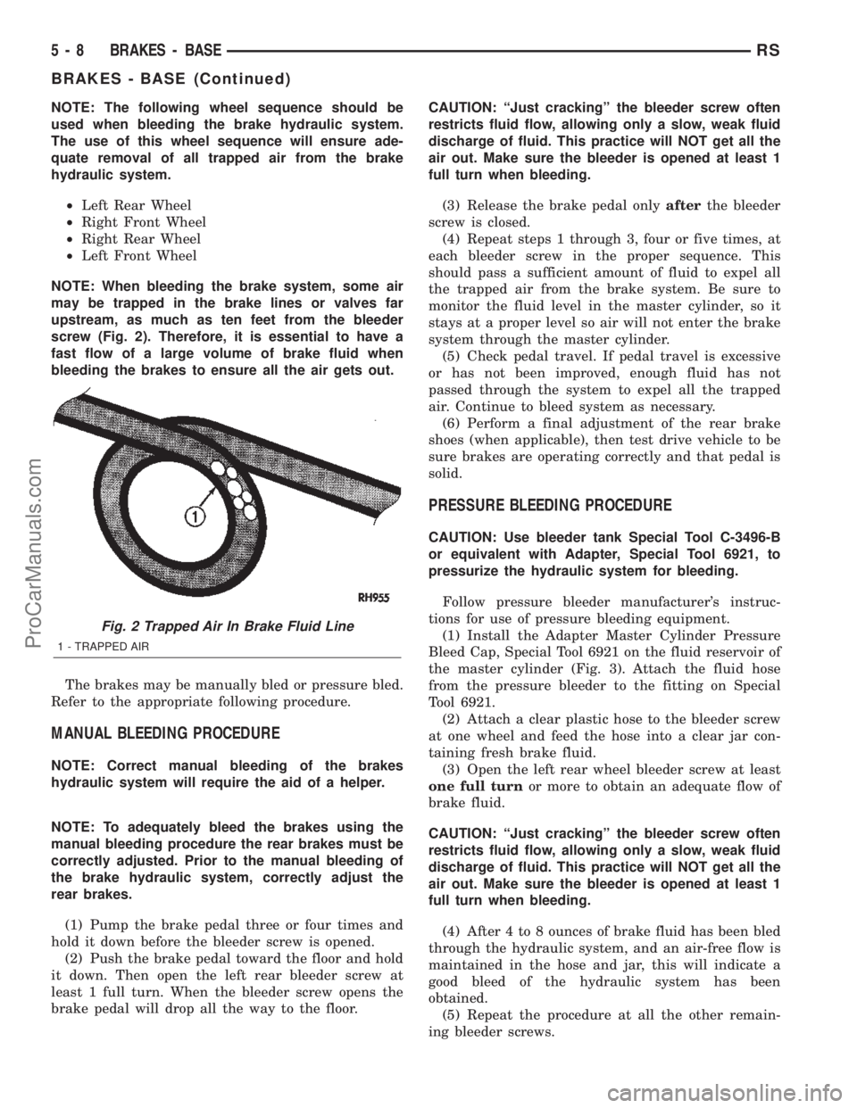
NOTE: When bleeding the brake system, some air
may be trapped in the brake lines or valves far
upstream, as much as ten feet from the bleeder
screw (Fig. 2). Therefore, it is essential to have a
fast flow of a large volume of brake fluid when
bleeding the brakes to ensure all the air gets out.
The brakes may be manually bled or pressure bled.
Refer to the appropriate following procedure.
MANUAL BLEEDING PROCEDURE
NOTE: Correct manual bleeding of the brakes
hydraulic system will require the aid of a helper.
NOTE: To adequately bleed the brakes using the
manual bleeding procedure the rear brakes must be
correctly adjusted. Prior to the manual bleeding of
the brake hydraulic system, correctly adjust the
rear brakes.
(1) Pump the brake pedal three or four times and
hold it down before the bleeder screw is opened.
(2) Push the brake pedal toward the floor and hold
it down. Then open the left rear bleeder screw at
least 1 full turn. When the bleeder screw opens the
brake pedal will drop all the way to the floor.CAUTION: ªJust crackingº the bleeder screw often
restricts fluid flow, allowing only a slow, weak fluid
discharge of fluid. This practice will NOT get all the
air out. Make sure the bleeder is opened at least 1
full turn when bleeding.
(3) Release the brake pedal onlyafterthe bleeder
screw is closed.
(4) Repeat steps 1 through 3, four or five times, at
each bleeder screw in the proper sequence. This
should pass a sufficient amount of fluid to expel all
the trapped air from the brake system. Be sure to
monitor the fluid level in the master cylinder, so it
stays at a proper level so air will not enter the brake
system through the master cylinder.
(5) Check pedal travel. If pedal travel is excessive
or has not been improved, enough fluid has not
passed through the system to expel all the trapped
air. Continue to bleed system as necessary.
(6) Perform a final adjustment of the rear brake
shoes (when applicable), then test drive vehicle to be
sure brakes are operating correctly and that pedal is
solid.
PRESSURE BLEEDING PROCEDURE
CAUTION: Use bleeder tank Special Tool C-3496-B
or equivalent with Adapter, Special Tool 6921, to
pressurize the hydraulic system for bleeding.
Follow pressure bleeder manufacturer's instruc-
tions for use of pressure bleeding equipment.
(1) Install the Adapter Master Cylinder Pressure
Bleed Cap, Special Tool 6921 on the fluid reservoir of
the master cylinder (Fig. 3). Attach the fluid hose
from the pressure bleeder to the fitting on Special
Tool 6921.
(2) Attach a clear plastic hose to the bleeder screw
at one wheel and feed the hose into a clear jar con-
taining fresh brake fluid.
(3) Open the left rear wheel bleeder screw at least
one full turnor more to obtain an adequate flow of
brake fluid.
CAUTION: ªJust crackingº the bleeder screw often
restricts fluid flow, allowing only a slow, weak fluid
discharge of fluid. This practice will NOT get all the
air out. Make sure the bleeder is opened at least 1
full turn when bleeding.
(4) After 4 to 8 ounces of brake fluid has been bled
through the hydraulic system, and an air-free flow is
maintained in the hose and jar, this will indicate a
good bleed of the hydraulic system has been
obtained.
(5) Repeat the procedure at all the other remain-
ing bleeder screws.
Fig. 2 Trapped Air In Brake Fluid Line
1 - TRAPPED AIR
5 - 8 BRAKES - BASERS
BRAKES - BASE (Continued)
ProCarManuals.com
Page 138 of 2399

(6) Check pedal travel. If pedal travel is excessive
or has not been improved, enough fluid has not
passed through the system to expel all the trapped
air. Be sure to monitor the fluid level in the pressure
bleeder, so it stays at a proper level so air will not
enter the brake system through the master cylinder.
(7) Perform a final adjustment of the rear brake
shoes (when applicable), then test drive vehicle to be
sure brakes are operating correctly and that pedal is
solid.
SPECIFICATIONS
BRAKE FASTENER TORQUE
DESCRIPTION N´mFt.
Lbs.In.
Lbs.
ABS ICU Mounting Bolts To
Bracket11 Ð 9 7
ABS ICU Mounting
Bracket-To-Cradle Bolts28 21 250
ABS CAB-To-HCU Mounting
Screws2Ð17
ABS Wheel Speed Sensor
Head Mounting Bolt - Front13 Ð 115
ABS Wheel Speed Sensor
Head Mounting Bolt - Rear10 Ð 90
Adjustable Pedal Position
Sensor Mounting Screws7.5 66 Ð
Adjustable Pedal Module
Mounting Screws2.0 15 Ð
DESCRIPTION N´mFt.
Lbs.In.
Lbs.
Brake Tube Nuts 17 Ð 145
Brake Hose Intermediate
Bracket Bolt12 Ð 105
Brake Hose-To-Caliper
Mounting Bolt47 35 Ð
Disc Brake Caliper Guide
Pin Bolts35 26 Ð
Disc Brake Caliper Bleeder
Screw15 Ð 125
Drum Brake Wheel Cylinder
Mounting Bolts8Ð75
Drum Brake Wheel Cylinder
Mounting Bleeder screw10 Ð 80
Drum Brake Support Plate
Mounting Bolts130 95 Ð
Junction Block (Non-ABS
Brakes) Mounting Bolts28 21 250
Master Cylinder Mounting
Nuts25 19 225
Power Brake Booster
Mounting Nuts28 21 250
Proportioning Valve
Mounting Bolts54 40 Ð
Proportioning Valve Axle
Bracket Mounting Bolt20 Ð 175
Parking Brake Lever (Pedal)
Mounting Bolts And Nut28 21 250
Wheel Mounting (Lug) Nuts 135 100 Ð
SPECIAL TOOLS
BASE BRAKE SYSTEM
Fig. 3 TOOL 6921 INSTALLED ON MASTER
CYLINDER
1 - SPECIAL TOOL 6921
2 - FLUID RESERVOIR
Tubes, Master Cylinder Bleeding 6920
RSBRAKES - BASE5-9
BRAKES - BASE (Continued)
ProCarManuals.com
Page 139 of 2399

BRAKE FLUID LEVEL SWITCH
DESCRIPTION
The brake fluid level switch is located in the brake
fluid reservoir of the master cylinder (Fig. 4).
OPERATION
The purpose of the brake fluid level switch is to
provide the driver with an early warning that the
brake fluid level in the master cylinder fluid reser-
voir has dropped below a normal level. This may
indicate:
²Abnormal loss of brake fluid in the master cyl-
inder fluid reservoir resulting from a leak in the
hydraulic system.
²Brake shoe linings which have worn to a point
requiring replacement.
As the brake fluid drops below the minimum level,
the brake fluid level switch closes to complete the red
BRAKE warning indicator (lamp) circuit. This will
turn on the red BRAKE warning indicator. The mas-
ter cylinder fluid reservoir should be checked and
refilled to the Full mark with DOT 3 brake fluid.If
the brake fluid level has dropped below the add
line in the master cylinder fluid reservoir, the
entire brake hydraulic system should be
checked for evidence of a leak.
REMOVAL
(1) Remove wiring harness connector from brake
fluid reservoir level switch (Fig. 4).
(2) Using fingers, compress the retaining tabs on
the opposite end of brake fluid level switch.
(3) With retaining tabs compressed, grasp the con-
nector end of brake fluid level switch and pull it out
of master cylinder brake fluid reservoir.
INSTALLATION
(1) Insert brake fluid level switch into left side of
brake fluid reservoir. Be sure switch is pushed in
until retaining tabs lock it to brake fluid reservoir.
(2) Connect vehicle wiring harness connector to
brake fluid level switch (Fig. 4).
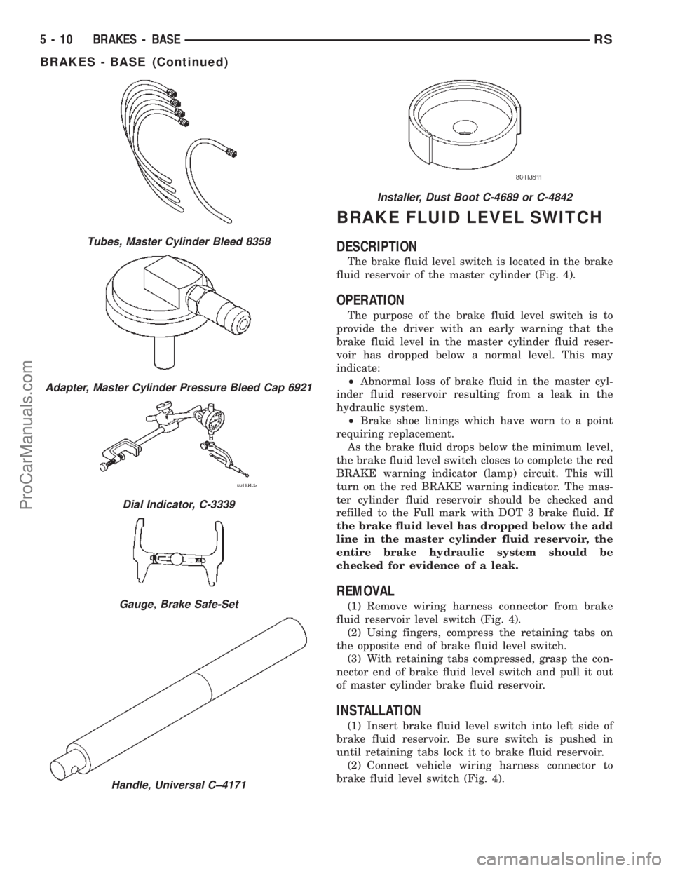
Tubes, Master Cylinder Bleed 8358
Adapter, Master Cylinder Pressure Bleed Cap 6921
Dial Indicator, C-3339
Gauge, Brake Safe-Set
Handle, Universal C±4171
Installer, Dust Boot C-4689 or C-4842
5 - 10 BRAKES - BASERS
BRAKES - BASE (Continued)
ProCarManuals.com
Page 140 of 2399

ADJUSTABLE PEDAL SWITCH
DESCRIPTION
The adjustable pedal switch is mounted on the left
side of the lower steering column shroud (Fig. 5). The
adjustable pedal switch adjusts the adjustable pedal
assembly fore-and-aft. The pedal assembly moves in
the direction the switch is actuated.
DIAGNOSIS AND TESTING - ADJUSTABLE
PEDAL SWITCH
Refer to Appropriate Diagnostic Information.
REMOVAL
NOTE: Before proceeding, review all Steering Col-
umn and Airbag Warnings and Cautions. (Refer to
19 - STEERING/COLUMN - WARNING)(Refer to 8 -
ELECTRICAL/RESTRAINTS - WARNING)
(1) Remove battery ground cable terminal from
battery negative post and isolate.
(2) Under instrument panel, remove silencer panel
below lower steering column cover.
(3) Remove screws securing lower steering column
cover/knee blocker, then remove it (Fig. 6).
(4) Disconnect parking brake release link at
release handle.
(5) Compress tabs on sides of data link diagnostic
connector and remove it from knee blocker reinforce-
ment plate.
(6) Remove screws securing knee blocker reinforce-
ment plate in place, then remove reinforcement plate
(Fig. 6).
(7) Remove screws fastening upper and lower
steering column shrouds to steering column (Fig. 7).
(8) Remove the lower shroud with adjustable pedal
switch; disconnect switch wiring connector along left
side of column as shroud is removed (Fig. 8).
Fig. 4 MASTER CYLINDER AND BOOSTER
1 - POWER BRAKE BOOSTER
2 - BOOSTER IDENTIFICATION LABEL
3 - FLUID LEVEL SWITCH CONNECTOR
4 - PRIMARY BRAKE TUBE NUT
5 - SECONDARY BRAKE TUBE NUT
6 - MASTER CYLINDER
Fig. 5 Adjustable Pedal Switch Location
1 - ADJUSTABLE PEDAL SWITCH
2 - LOWER STEERING COLUMN SHROUD
Fig. 6 Lower Steering Column Cover And
Reinforcement
1 - INSTRUMENT PANEL
2 - REINFORCEMENT PLATE
3 - LOWER STEERING COLUMN COVER/KNEE BLOCKER
RSBRAKES - BASE5-11
BRAKE FLUID LEVEL SWITCH (Continued)
ProCarManuals.com
Page 141 of 2399

(9) Depress retainers on rear of adjustable pedal
switch, then remove switch from lower shroud (Fig.
9).
INSTALLATION
(1) Guide adjustable pedal switch wiring through
mounting hole in lower shroud.
(2) Align switch retainers with notches in mount-
ing hole and snap the switch into place (Fig. 9).
(3) Connect adjustable pedal switch wiring connec-
tor along left side of column (Fig. 8).(4) Install the lower shroud with adjustable pedal
switch. Install screws fastening steering column
shrouds to steering column (Fig. 7).
(5) Install knee blocker reinforcement plate (Fig.
6).
(6) Connect parking brake release link to release
handle.
(7) Install data link diagnostic connector to mount-
ing hole in reinforcement plate.
(8) Install lower steering column cover/knee
blocker (Fig. 6).
(9) Install silencer panel below lower steering col-
umn cover/knee blocker.
(10) Connect ground cable to negative post of bat-
tery.
(11) Connect scan tool (DRBIIIt) to data link diag-
nostic connector located below steering column.
(12) Turn ignition key to ON position.
(13) Using scan tool, check for and clear any exist-
ing adjustable pedal fault codes.
(14) Test operation of adjustable pedals, memory
sets and RKE (if equipped). If applicable, reset radio
and clock.
(15) Recheck for any fault codes.
(16) Turn key to OFF and remove scan tool from
vehicle.
PEDAL POSITION SENSOR
DESCRIPTION
The pedal position sensor is part of the adjustable
pedal assembly. It is mounted to the left of the brake
pedal (Fig. 10). It senses the fore and aft position of
the brake pedal.
Fig. 7 Steering Column Shrouds
1 - FIXED SHROUD
2 - UPPER SHROUD
3 - CLOCKSPRING
4 - LOWER SHROUD
5 - STEERING COLUMN
Fig. 8 Pedal Switch Wiring Connector
1 - STEERING COLUMN FIXED SHROUD
2 - BRAKE TRANSMISSION SHIFT INTERLOCK
3 - B.T.S.I. WIRING CONNECTOR
4 - PEDAL SWITCH WIRING CONNECTOR
Fig. 9 Pedal Switch Retainers
1 - LOWER SHROUD INTERIOR
2 - RETAINERS
5 - 12 BRAKES - BASERS
ADJUSTABLE PEDAL SWITCH (Continued)
ProCarManuals.com