Page 1526 of 2399

(10) Install the cluster trim bezel (Refer to 23 -
BODY/INSTRUMENT PANEL/CLUSTER BEZEL -
INSTALLATION).
(11) Install the upper and lower shrouds (Refer to
19 - STEERING/COLUMN/LOWER SHROUD -
INSTALLATION).
(12) Install the knee blocker reinforcement (Refer
to 23 - BODY/INSTRUMENT PANEL/KNEE
BLOCKER - INSTALLATION).
(13) Install the knee blocker (Refer to 23 - BODY/
INSTRUMENT PANEL/STEERING COLUMN
OPENING COVER - INSTALLATION).
SHROUD
REMOVAL
(1) Remove the three screws from the lower
shroud.
(2) Unsnap and remove the lower shroud.
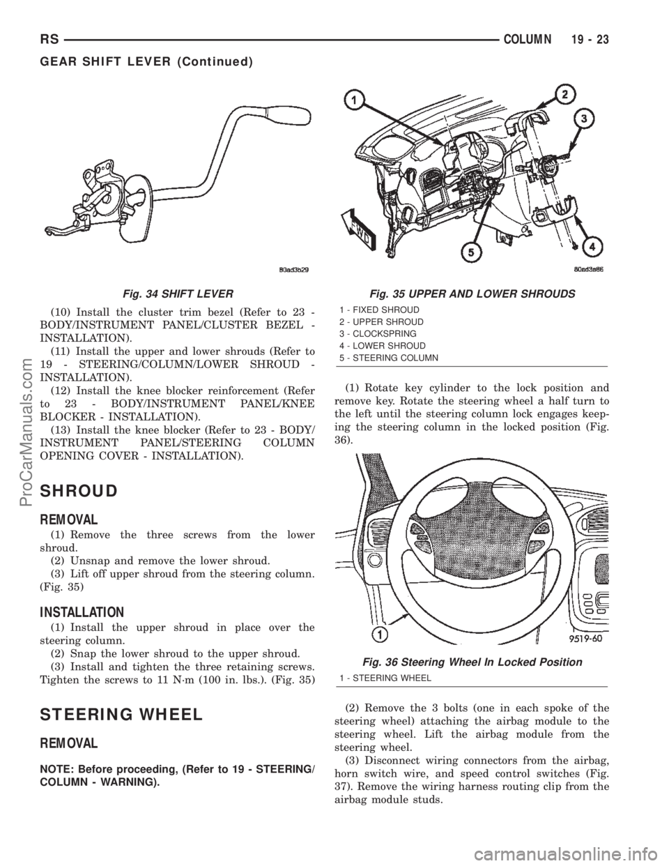
(3) Lift off upper shroud from the steering column.
(Fig. 35)
INSTALLATION
(1) Install the upper shroud in place over the
steering column.
(2) Snap the lower shroud to the upper shroud.
(3) Install and tighten the three retaining screws.
Tighten the screws to 11 N´m (100 in. lbs.). (Fig. 35)
STEERING WHEEL
REMOVAL
NOTE: Before proceeding, (Refer to 19 - STEERING/
COLUMN - WARNING).(1) Rotate key cylinder to the lock position and
remove key. Rotate the steering wheel a half turn to
the left until the steering column lock engages keep-
ing the steering column in the locked position (Fig.
36).
(2) Remove the 3 bolts (one in each spoke of the
steering wheel) attaching the airbag module to the
steering wheel. Lift the airbag module from the
steering wheel.
(3) Disconnect wiring connectors from the airbag,
horn switch wire, and speed control switches (Fig.
37). Remove the wiring harness routing clip from the
airbag module studs.
Fig. 34 SHIFT LEVERFig. 35 UPPER AND LOWER SHROUDS
1 - FIXED SHROUD
2 - UPPER SHROUD
3 - CLOCKSPRING
4 - LOWER SHROUD
5 - STEERING COLUMN
Fig. 36 Steering Wheel In Locked Position
1 - STEERING WHEEL
RSCOLUMN19-23
GEAR SHIFT LEVER (Continued)
ProCarManuals.com
Page 1841 of 2399

VEHICLE SPEED SIGNAL
The vehicle speed signal is taken from the Output
Speed Sensor. The TCM converts this signal into a
pulse per mile signal and sends it to the PCM. The
PCM, in turn, sends the vehicle speed message
across the communication bus to the BCM. The BCM
sends this signal to the Instrument Cluster to dis-
play vehicle speed to the driver. The vehicle speed
signal pulse is roughly 8000 pulses per mile.
REMOVAL
(1) Disconnect battery negative cable.
(2) Raise vehicle on hoist.
(3) Disconnect output speed sensor connector.
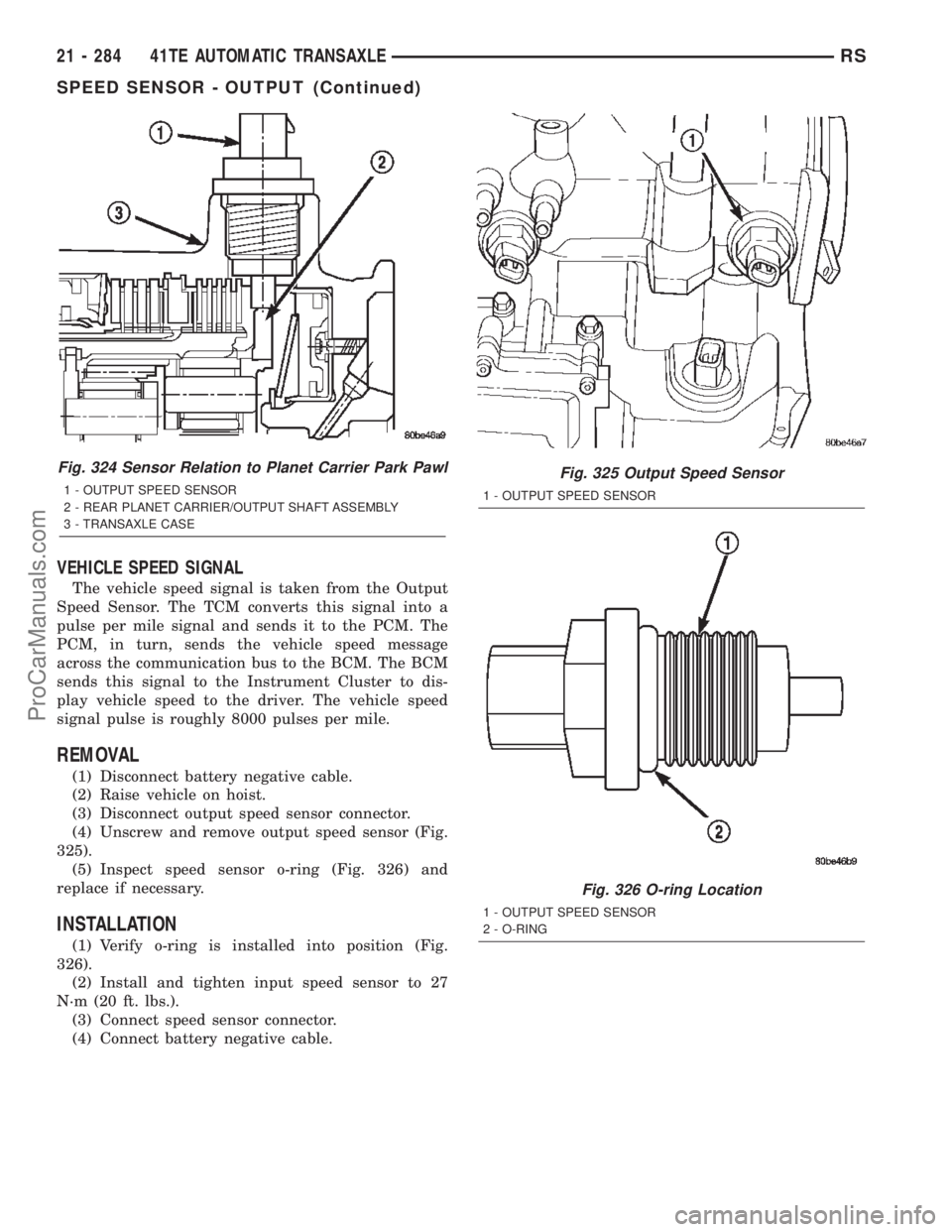
(4) Unscrew and remove output speed sensor (Fig.
325).
(5) Inspect speed sensor o-ring (Fig. 326) and
replace if necessary.
INSTALLATION
(1) Verify o-ring is installed into position (Fig.
326).
(2) Install and tighten input speed sensor to 27
N´m (20 ft. lbs.).
(3) Connect speed sensor connector.
(4) Connect battery negative cable.
Fig. 324 Sensor Relation to Planet Carrier Park Pawl
1 - OUTPUT SPEED SENSOR
2 - REAR PLANET CARRIER/OUTPUT SHAFT ASSEMBLY
3 - TRANSAXLE CASE
Fig. 325 Output Speed Sensor
1 - OUTPUT SPEED SENSOR
Fig. 326 O-ring Location
1 - OUTPUT SPEED SENSOR
2 - O-RING
21 - 284 41TE AUTOMATIC TRANSAXLERS
SPEED SENSOR - OUTPUT (Continued)
ProCarManuals.com
Page 2046 of 2399

INSTRUMENT PANEL
TABLE OF CONTENTS
page page
CLUSTER BEZEL
REMOVAL.............................63
INSTALLATION.........................63
CUP HOLDER
REMOVAL.............................64
INSTALLATION.........................64
GLOVE BOX
REMOVAL.............................64
INSTALLATION.........................64
GLOVE BOX LATCH
REMOVAL.............................64
INSTALLATION.........................64
GLOVE BOX LATCH STRIKER
REMOVAL.............................64
INSTALLATION.........................65
INSTRUMENT PANEL ASSEMBLY
REMOVAL.............................65
INSTALLATION.........................67
INSTRUMENT PANEL CENTER BEZEL
REMOVAL.............................68
INSTALLATION.........................68INSTRUMENT PANEL END CAP
REMOVAL.............................68
INSTALLATION.........................68
INSTRUMENT PANEL TOP COVER
REMOVAL.............................69
INSTALLATION.........................69
LOWER CONSOLE
REMOVAL.............................69
INSTALLATION.........................69
LOWER INSTRUMENT PANEL
REMOVAL.............................70
INSTALLATION.........................70
LOWER STEERING COLUMN COVER
REMOVAL.............................70
INSTALLATION.........................70
STEERING COLUMN COVER BACKING PLATE
REMOVAL.............................70
INSTALLATION.........................71
OVER STEERING COLUMN COVER
REMOVAL.............................71
INSTALLATION.........................71
CLUSTER BEZEL
REMOVAL
(1) Disconnect and isolate the battery negative
cable.
(2) Remove Over Steering Column Bezel by lifting
it straight up with a firm pull.
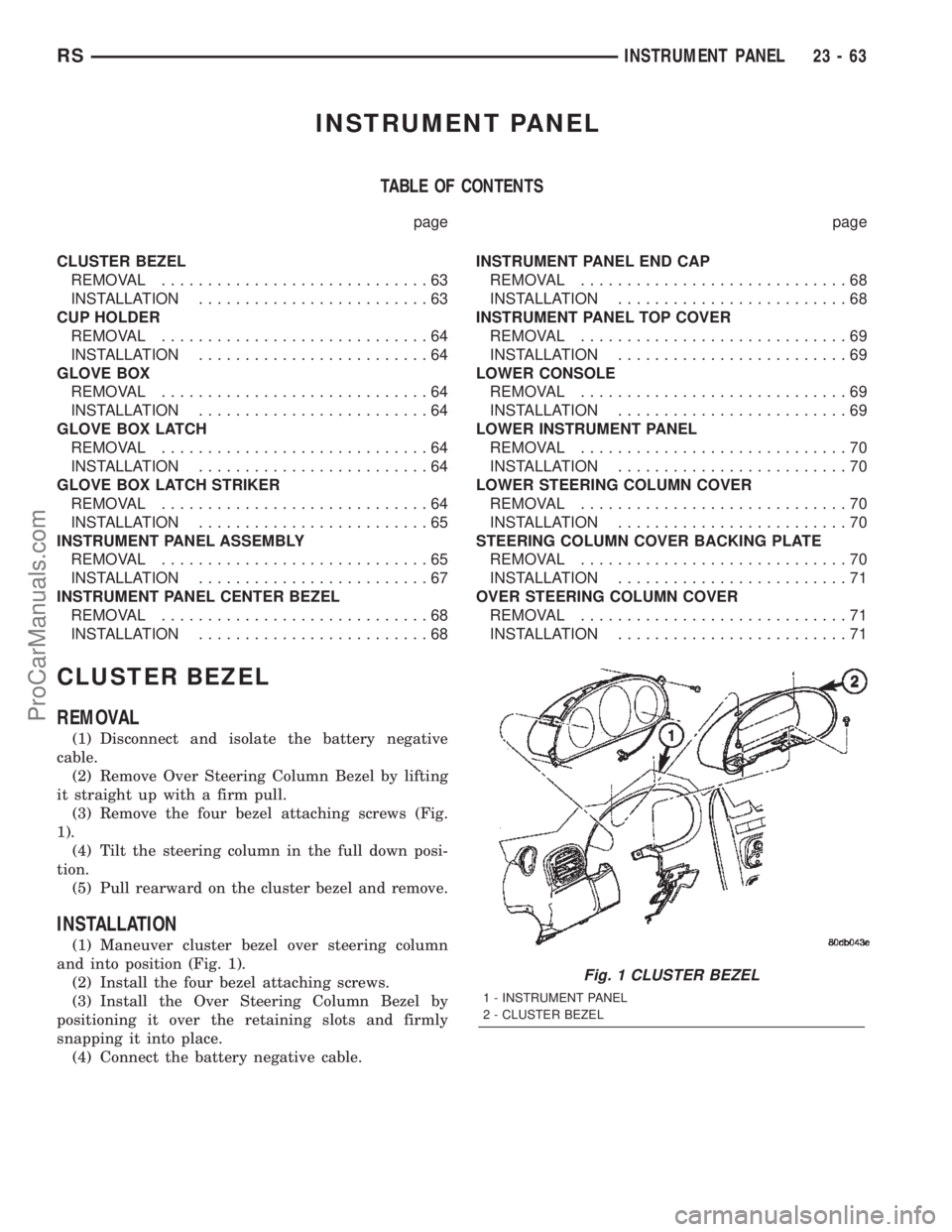
(3) Remove the four bezel attaching screws (Fig.
1).
(4) Tilt the steering column in the full down posi-
tion.
(5) Pull rearward on the cluster bezel and remove.
INSTALLATION
(1) Maneuver cluster bezel over steering column
and into position (Fig. 1).
(2) Install the four bezel attaching screws.
(3) Install the Over Steering Column Bezel by
positioning it over the retaining slots and firmly
snapping it into place.
(4) Connect the battery negative cable.
Fig. 1 CLUSTER BEZEL
1 - INSTRUMENT PANEL
2 - CLUSTER BEZEL
RSINSTRUMENT PANEL23-63
ProCarManuals.com