2002 CHRYSLER CARAVAN ECO mode
[x] Cancel search: ECO modePage 636 of 2399

able, Sentry Key programming will require the use of
a DRB IIItscan tool.
The steps required to program Sentry Keys with
two valid Sentry Keys follows:
(1) Obtain the blank Sentry Key(s) that need to be
programmed. Cut the keys to match the ignition lock
cylinder mechanical key codes.
(2) Insert one of the two valid Sentry Keys into the
ignition switch and turn the ignition switch to the
ON position.
(3) After the ignition switch has been in the ON
position for longer than three seconds, but no more
than fifteen seconds, cycle the ignition switch back to
the OFF position. Replace the first valid Sentry Key
in the ignition lock cylinder with the second valid
Sentry Key and turn the ignition switch back to the
ON position. The second valid Sentry Key must be
inserted within 15 seconds of removing the first valid
Sentry key.
(4) About ten seconds after the completion of Step
3, the indicator light will start to flash and a single
audible chime tone will sound to indicate that the
system has entered the9Customer Learn9program-
ming mode.
(5) Within sixty seconds of entering the9Customer
Learn9programming mode, turn the ignition switch
to the OFF position, replace the valid Sentry Key
with a blank Sentry Key transponder, and turn the
ignition switch back to the ON position.
(6) About ten seconds after the completion of Step
5, a single audible chime tone will sound and the
indicator light will stop flashing and stay on solid for
three seconds and then turn off to indicate that the
blank Sentry Key has been successfully programmed.
The SKIS will immediately exit the9Customer
Learn9programming mode and the vehicle may be
started using the newly programmed Sentry Key.
These steps must be completed in their entirety for
each additional Sentry Key to be programmed. If any
of the above steps are not completed in the given
sequence, or within the allotted time, the SKIS will
exit the9Customer Learn9programming mode and
the programming will be unsuccessful. The SKIS will
also automatically exit the9Customer Learn9pro-
gramming mode if:
²It sees a non-blank Sentry Key when it should
see a blank.
²If it has already programmed eight (8) valid
Sentry Keys.
²If the ignition switch is turned to the OFF posi-
tion for more than about fifty (50) seconds.NOTE: If you attempt to start the vehicle while in
ªCustomer Learnº mode (LED flashing), the vehicle
will behave as though an invalid key is being used
(i.e. the engine will stall after two (2) seconds of
running). No faults will be logged.
NOTE: Once a Sentry Key has been programmed to
a particular vehicle, it cannot be used on any other
vehicle.
VTSS/SKIS INDICATOR LAMP
DESCRIPTION
The Sentry Key Immobilizer System (SKIS) uses
an indicator light to convey information on the status
of the system to the customer. This light is shared
with the Vehicle Theft Security System (VTSS). The
light is located in the Message Center. The indicator
light is controlled by the Body Control Module (BCM)
based upon messages it receives from the Sentry Key
Immobilizer Module (SKIM) on the PCI bus.
OPERATION
The BCM performs a four second bulb check,
regardless of SKIM messages. After the bulb check,
the lamp is controlled according to SKIM messages.
Then, the SKIM sends messages to the BCM to oper-
ate the light based upon the results of the SKIS self
tests. The light may be actuated in two possible
ways, flashing or on solid. If the light comes on and
stays on solid after a power-up test, this indicates
that the SKIM has detected a system malfunction. If
the SKIM detects an invalid key when the ignition
switch is moved to the ON position, it sends a mes-
sage on the PCI bus to the BCM, to flash the light.
The SKIM can also send a message to flash the light
and generate a single audible chime at the same
time. These two events occurring simultaneously
indicate that the SKIS has been placed into the9Cus-
tomer Learn9mode. Refer to Electrical, Vehicle Theft
Security, Transponder Key, Standard Procedure -
Transponder Programming for more information on
the9Customer Learn9mode. If the light comes on
and stays on after the power-up test, diagnosis of the
SKIS should be performed using a DRB IIItscan tool
and the appropriate Body Diagnostic Procedures
manual. The light is not a serviceable component.
RSVEHICLE THEFT SECURITY8Q-5
TRANSPONDER KEY (Continued)
ProCarManuals.com
Page 639 of 2399

OPERATION
FRONT WIPER/WASHER SYSTEM
The windshield washer circuit is protected by a 15
amp Cartridge Fuse located in the IPM. The wiper
motor has permanent magnetic fields. The speeds are
determined by current flow to the appropriate set of
brushes inside the motor. The current flow is con-
trolled by the multi-function switch. The high speed/
low speed relays are located in the IPM. The speed
sensitive intermittent wiper is controlled by the Body
Control Module (BCM). The intermittent mode, with
the vehicle traveling greater than 10.4 mph, has a
range of 0.5 to 18 seconds. With the vehicle traveling
less than 10.4 mph, the time delay doubles to a
range of 1 to 36 seconds. The wiper arms will park at
the base of the windshield just above the cowl cover
after the wiper switch is turned OFF.
The windshield wiper motor and linkage is located
in an integral wiper unit at the rear of the engine
compartment. The wiper unit must be removed to
gain access to the wiper motor.
REAR WIPER/WASHER SYSTEM
When continuous rear wiper operation is required,
the BCM will provide ignition ON voltage to the rear
wiper motor. When the wiper switch is turned OFF,
the BCM provides circuit ground to operate the
motor until the wipe cycle is complete and the wiper
arm returns to the base of the rear window.
When intermittent rear wiper mode is selected, the
wiper motor will cycle every 7 seconds. The intermit-
tent delay time is also adjusted based upon vehicle
speed. With the vehicle traveling greater than 50
mph, the cycle changes to every 5 seconds.
DIAGNOSIS AND TESTING
DIAGNOSIS AND TESTING - FRONT WIPER
SYSTEM
The windshield wiper system operates in several
modes:
²Low and high speed normal wipe²Speed sensitive intermittent wipe
²Wipe after wash
²Park (switch OFF)
The windshield wiper circuits are continuously
monitored and controlled by the Body Control Mod-
ule (BCM). If a problem occurs in the electronic com-
ponents, wiring, switch (except integral motor park
switch) and wiper motor a Diagnostic Trouble Code
(DTC) will be stored in the BCM memory. DTC's can
be retrieved using a DRB IIItscan tool. Refer to the
proper Body Diagnostic Procedures manual for DTC
descriptions and retrieval information.
The windshield wiper park switch and circuit is
monitored by the BCM. The park switch and circuit
can be tested using the Wiper System Diagnosis
table.
DIAGNOSIS AND TESTING - FRONT
WIPER/WASHER SWITCH
(1) Remove the multi-function switch (Refer to 8 -
ELECTRICAL/LAMPS/LIGHTING - EXTERIOR/
MULTI-FUNCTION SWITCH - REMOVAL).
(2) Using an ohmmeter check resistance readings
between switch pins. Refer to the WIPER/WASHER
SWITCH RESISTANCE table.
WIPER/WASHER SWITCH RESISTANCE
SWITCH POSITION RESISTANCE BETWEEN
OFF 4 AND 3 = OPEN CIRCUIT
DELAY POSITION
1ST 3 AND 4 = 3.3KV 5%
2ND 3 AND 4 = 1.7KV 5%
3RD 3AND4=1KV 5%
4TH 3 AND 4 = 620V 5%
5TH 3 AND 4 = 620V 5%
LOW 3 AND 4 = 430V 5%
HIGH 3 AND4=240V 5%
WASH 1 AND 3 = 5.9KV 5%
8R - 2 WIPERS/WASHERSRS
WIPERS/WASHERS (Continued)
ProCarManuals.com
Page 665 of 2399

DESCRIPTION - CIRCUIT FUNCTIONS
All circuits in the diagrams use an alpha/numeric
code to identify the wire and it's function. To identify
which circuit code applies to a system, refer to the
Circuit Identification Code Chart. This chart shows
the main circuits only and does not show the second-
ary codes that may apply to some models.
CIRCUIT IDENTIFICATION CODE CHART
CIRCUIT FUNCTION
A BATTERY FEED
B BRAKE CONTROLS
C CLIMATE CONTROLS
D DIAGNOSTIC CIRCUITS
E DIMMING ILLUMINATION
CIRCUITS
F FUSED CIRCUITS
G MONITORING CIRCUITS
(GAUGES)
H OPEN
I NOT USED
J OPEN
K POWERTRAIN CONTROL
MODULE
L EXTERIOR LIGHTING
M INTERIOR LIGHTING
N NOT USED
O NOT USED
P POWER OPTION (BATTERY
FEED)
Q POWER OPTIONS (IGNITION
FEED)
R PASSIVE RESTRAINT
S SUSPENSION/STEERING
T TRANSMISSION/TRANSAXLE/
TRANSFER CASE
U OPEN
V SPEED CONTROL, WIPER/
WASHER
W OPEN
X AUDIO SYSTEMS
Y OPEN
Z GROUNDS
DESCRIPTION - SECTION IDENTIFICATION AND
INFORMATION
The wiring diagrams are grouped into individual
sections. If a component is most likely found in a par-
ticular group, it will be shown complete (all wires,
connectors, and pins) within that group. For exam-
ple, the Auto Shutdown Relay is most likely to be
found in Group 30, so it is shown there complete. It
can, however, be shown partially in another group if
it contains some associated wiring.
Splice diagrams in Section 8W-70 show the entire
splice and provide references to other sections the
splices serves. Section 8W-70 only contains splice dia-
grams that are not shown in their entirety some-
where else in the wiring diagrams.
Section 8W-80 shows each connector and the cir-
cuits involved with that connector. The connectors
are identified using the name/number on the dia-
gram pages.
WIRING SECTION CHART
GROUP TOPIC
8W-01 thru
8W-09General information and Diagram
Overview
8W-10 thru
8W-19Main Sources of Power and
Vehicle Grounding
8W-20 thru
8W-29Starting and Charging
8W-30 thru
8W-39Powertrain/Drivetrain Systems
8W-40 thru
8W-49Body Electrical items and A/C
8W-50 thru
8W-59Exterior Lighting, Wipers and
Trailer Tow
8W-60 thru
8W-69Power Accessories
8W-70 Splice Information
8W-80 Connector Pin Outs
8W-91 Connector, Ground and Splice
Locations
8W - 01 - 6 8W-01 WIRING DIAGRAM INFORMATIONRS
WIRING DIAGRAM INFORMATION (Continued)
ProCarManuals.com
Page 1198 of 2399
(4) The coil ground terminal (85) is connected to
the electromagnet in the relay. It receives battery
feed to energize the accessory relay when the ignition
switch is in the Accessory or On positions. Turn the
ignition switch to the On position. Check for battery
voltage at the fused ignition switch output (acc/run)
circuit cavity for relay terminal 85 in the IPM recep-
tacle for the accessory relay. If OK, go to Step 5. If
not OK, repair the open fused ignition switch output
(acc/run) circuit to the ignition switch as required.
(5) The coil battery terminal (86) is connected to
the electromagnet in the relay. The IPM cavity for
this terminal should have continuity to ground at all
times. If not OK, repair the open ground circuit to
ground as required.
REMOVAL
(1) Disconnect and isolate the battery negative
cable.
(2) Remove the Integrated Power Module (IPM)
cover from the IPM.
(3) Remove the accessory relay from the IPM.
Refer to the IPM cover for relay location.
INSTALLATION
(1) Position the accessory relay in the proper
receptacle in the Integrated Power Module (IPM).
(2) Push in firmly on the accessory relay until the
terminals are fully seated in the terminal cavities in
the IPM receptacle.
(3) Install the IPM cover.
(4) Reconnect the battery negative cable.
INTEGRATED POWER MODULE
DESCRIPTION
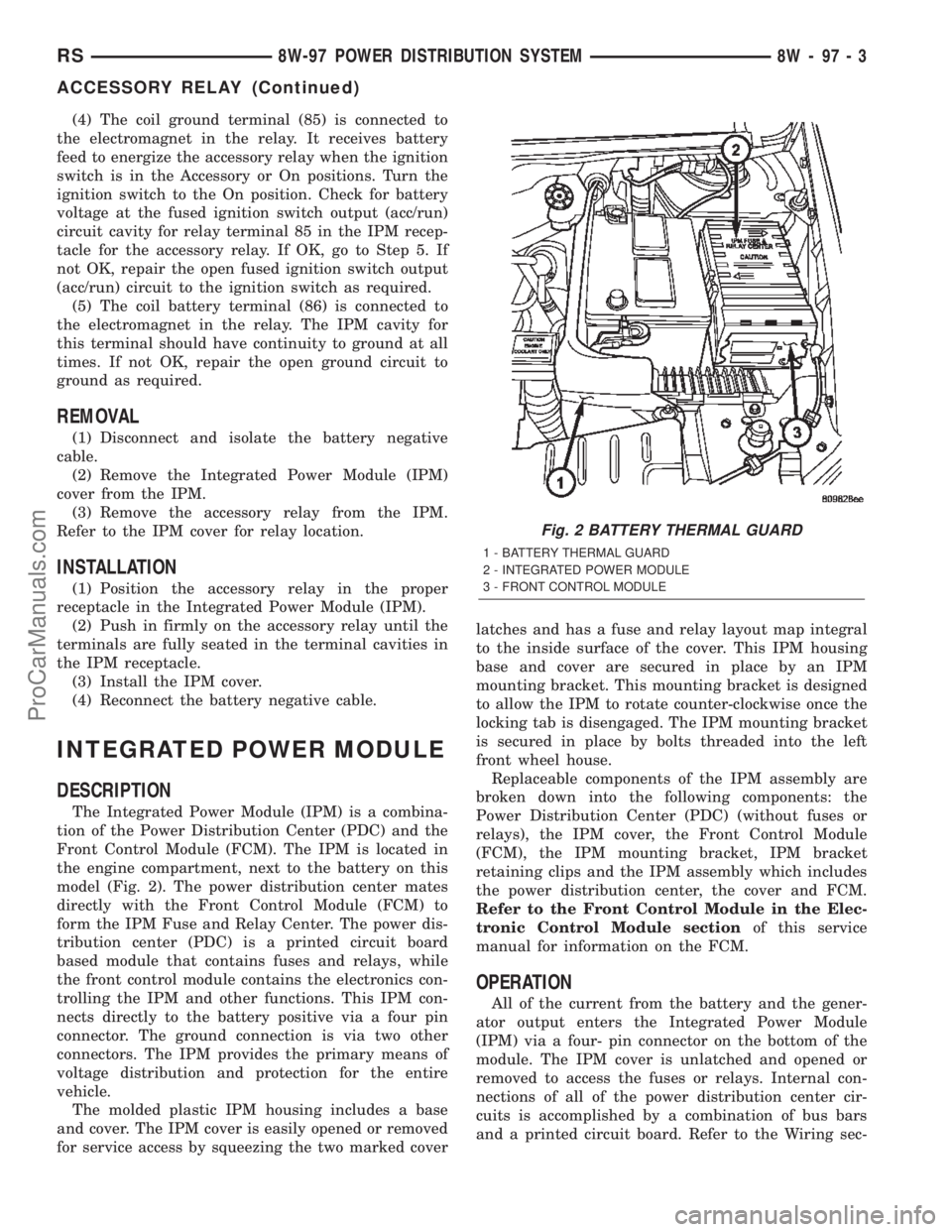
The Integrated Power Module (IPM) is a combina-
tion of the Power Distribution Center (PDC) and the
Front Control Module (FCM). The IPM is located in
the engine compartment, next to the battery on this
model (Fig. 2). The power distribution center mates
directly with the Front Control Module (FCM) to
form the IPM Fuse and Relay Center. The power dis-
tribution center (PDC) is a printed circuit board
based module that contains fuses and relays, while
the front control module contains the electronics con-
trolling the IPM and other functions. This IPM con-
nects directly to the battery positive via a four pin
connector. The ground connection is via two other
connectors. The IPM provides the primary means of
voltage distribution and protection for the entire
vehicle.
The molded plastic IPM housing includes a base
and cover. The IPM cover is easily opened or removed
for service access by squeezing the two marked coverlatches and has a fuse and relay layout map integral
to the inside surface of the cover. This IPM housing
base and cover are secured in place by an IPM
mounting bracket. This mounting bracket is designed
to allow the IPM to rotate counter-clockwise once the
locking tab is disengaged. The IPM mounting bracket
is secured in place by bolts threaded into the left
front wheel house.
Replaceable components of the IPM assembly are
broken down into the following components: the
Power Distribution Center (PDC) (without fuses or
relays), the IPM cover, the Front Control Module
(FCM), the IPM mounting bracket, IPM bracket
retaining clips and the IPM assembly which includes
the power distribution center, the cover and FCM.
Refer to the Front Control Module in the Elec-
tronic Control Module sectionof this service
manual for information on the FCM.
OPERATION
All of the current from the battery and the gener-
ator output enters the Integrated Power Module
(IPM) via a four- pin connector on the bottom of the
module. The IPM cover is unlatched and opened or
removed to access the fuses or relays. Internal con-
nections of all of the power distribution center cir-
cuits is accomplished by a combination of bus bars
and a printed circuit board. Refer to the Wiring sec-
Fig. 2 BATTERY THERMAL GUARD
1 - BATTERY THERMAL GUARD
2 - INTEGRATED POWER MODULE
3 - FRONT CONTROL MODULE
RS8W-97 POWER DISTRIBUTION SYSTEM8W-97-3
ACCESSORY RELAY (Continued)
ProCarManuals.com
Page 1200 of 2399
tion. The IOD fuse is a 15 ampere blade-type car-
tridge fuse and, when removed, it is stored in a fuse
cavity adjacent to the washer fuse within the IPM.
OPERATION
The term ignition-off draw identifies a normal con-
dition where power is being drained from the battery
with the ignition switch in the Off position. The IOD
fuse feeds the memory and sleep mode functions for
some of the electronic modules in the vehicle as well
as various other accessories that require battery cur-
rent when the ignition switch is in the Off position,
including the clock. The only reason the IOD fuse is
removed is to reduce the normal IOD of the vehicle
electrical system during new vehicle transportation
and pre-delivery storage to reduce battery depletion,
while still allowing vehicle operation so that the
vehicle can be loaded, unloaded and moved as needed
by both vehicle transportation company and dealer
personnel.
The IOD fuse is removed from the IPM fuse cavity
when the vehicle is shipped from the assembly plant.
Dealer personnel must install the IOD fuse when the
vehicle is being prepared for delivery in order to
restore full electrical system operation. Once the
vehicle is prepared for delivery, the IOD function of
this fuse becomes transparent and the fuse that has
been assigned the IOD designation becomes only
another Fused B(+) circuit fuse. The IOD fuse serves
no useful purpose to the dealer technician in the ser-
vice or diagnosis of any vehicle system or condition,
other than the same purpose as that of any other
standard circuit protection device.
The IOD fuse can be used by the vehicle owner as
a convenient means of reducing battery depletion
when a vehicle is to be stored for periods not to
exceed about thirty days. However, it must be
remembered that removing the IOD fuse will not
eliminate IOD, but only reduce this normal condition.
If a vehicle will be stored for more than about thirty
days, the battery negative cable should be discon-
nected to eliminate normal IOD; and, the battery
should be tested and recharged at regular intervals
during the vehicle storage period to prevent the bat-
tery from becoming discharged or damaged. Refer to
Battery Systemfor additional service information.
REMOVAL
(1) Turn the ignition switch to the Off position.
(2) Unlatch and open the cover of the intelligent
power module.
(3) Remove the IOD fuse from fuse location
markedIODof the Integrated Power Module (IPM).
(4) Store the removed IOD fuse by installing it in
the unused fuse storage markedSPAREof the IPM.
(5) Close and latch the IPM.
INSTALLATION
(1) Be certain the ignition switch is in the Off posi-
tion.
(2) Unlatch and open the cover of the Integrated
Power Module (IPM).
(3) Remove the stored 15 amp IOD fuse from fuse
storage markedSPAREof the IPM.
(4) Use a thumb to press the IOD fuse firmly down
into IPM fuse cavity markedIOD.
(5) Close and latch the IPM cover.
POWER OUTLET
DESCRIPTION
Accessory power outlets are standard equipment on
this model. Two power outlets are installed in the
instrument panel center lower bezel, which is located
near the bottom of the instrument panel center stack
area. Two additional power outlets are also incorpo-
rated into the vehicle, one on the left rear C-pillar
trim and the other in the center console, if equipped.
The power outlets bases are secured by a snap fit in
the appropriate bezels. A hinged plug flips closed to
conceal and protect the power outlet base when the
power outlet is not being used.
The power outlet receptacle unit and the power
outlet plugs are each available for service replace-
ment.
OPERATION
The power outlet base or receptacle shell is con-
nected to ground, and an insulated contact in the
bottom of the shell is connected to battery current.
The power outlet on the instrument panel marked
with a battery receives battery voltage from a fuse in
the Integrated Power Module (IPM) at all times. The
other power outlet on the instrument panel marked
with a key receives battery voltage only when the
key is in the on position.
The power outlet located in the center console
receives battery voltage all the time when positioned
between thefront seatsand key-on voltage when
positioned between therear seats. The power outlet
located on the C-pillar receives battery voltage only
when the key is in the on position.
DIAGNOSIS AND TESTING
DIAGNOSIS & TESTING - POWER OUTLET
For complete circuit diagrams, refer toCigar
Lighter/Power Outletin Wiring Diagrams.
RS8W-97 POWER DISTRIBUTION SYSTEM8W-97-5
IOD FUSE (Continued)
ProCarManuals.com
Page 1461 of 2399
INSTALLATION
INSTALLATION - 2.4L
(1) Ensure injector holes are clean. Replace
O-rings if damaged.
(2) Lubricate injector O-rings with a drop of clean
engine oil to ease installation.
(3) Put the tip of each injector into their ports.
Push the assembly into place until the injectors are
seated in the ports.
(4) Install the fuel rail mounting bolts. Tighten
bolts to 22 N´m (200 in. lbs.) torque.
(5) Connect the connectors to the fuel injectors.
(6) Install wiring harness to brackets.
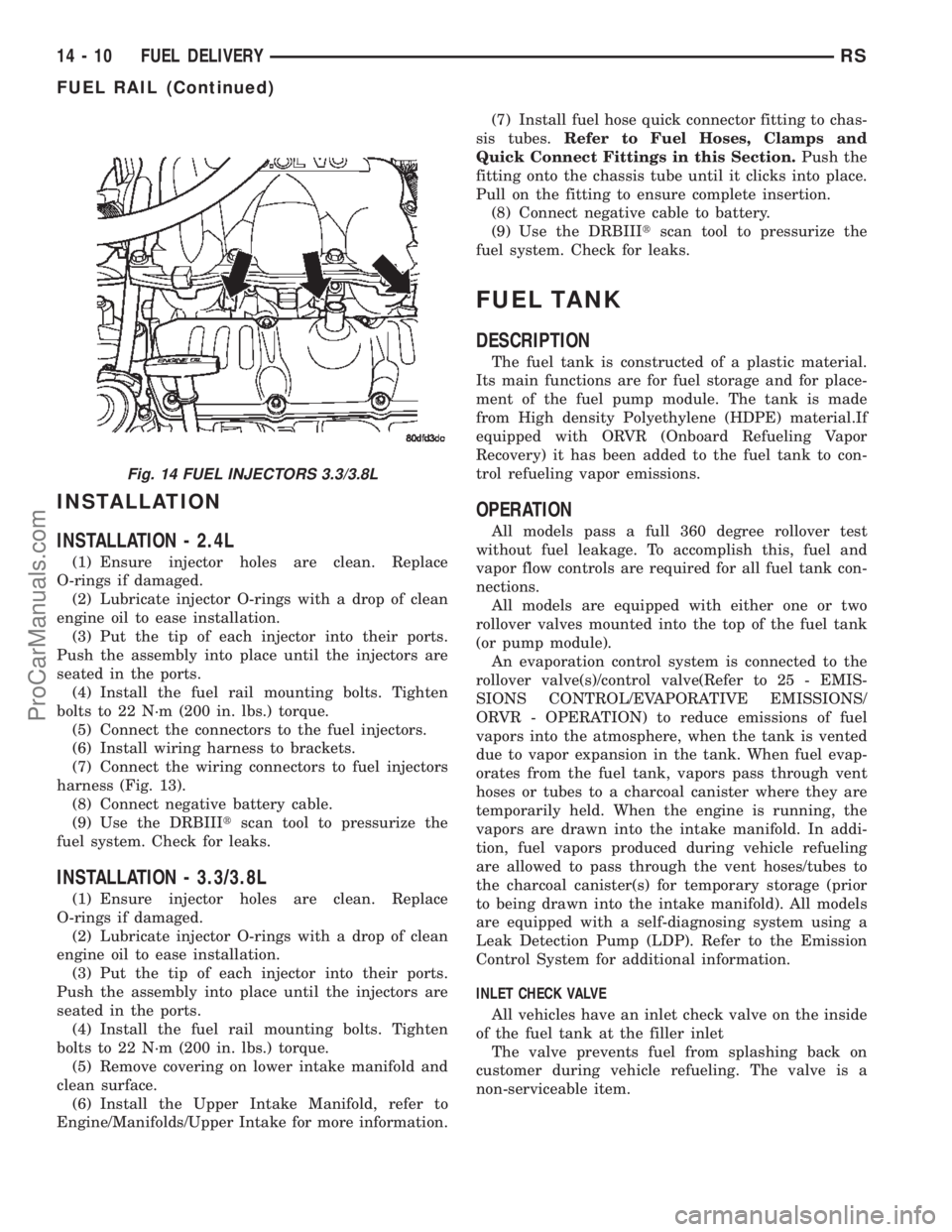
(7) Connect the wiring connectors to fuel injectors
harness (Fig. 13).
(8) Connect negative battery cable.
(9) Use the DRBIIItscan tool to pressurize the
fuel system. Check for leaks.
INSTALLATION - 3.3/3.8L
(1) Ensure injector holes are clean. Replace
O-rings if damaged.
(2) Lubricate injector O-rings with a drop of clean
engine oil to ease installation.
(3) Put the tip of each injector into their ports.
Push the assembly into place until the injectors are
seated in the ports.
(4) Install the fuel rail mounting bolts. Tighten
bolts to 22 N´m (200 in. lbs.) torque.
(5) Remove covering on lower intake manifold and
clean surface.
(6) Install the Upper Intake Manifold, refer to
Engine/Manifolds/Upper Intake for more information.(7) Install fuel hose quick connector fitting to chas-
sis tubes.Refer to Fuel Hoses, Clamps and
Quick Connect Fittings in this Section.Push the
fitting onto the chassis tube until it clicks into place.
Pull on the fitting to ensure complete insertion.
(8) Connect negative cable to battery.
(9) Use the DRBIIItscan tool to pressurize the
fuel system. Check for leaks.
FUEL TANK
DESCRIPTION
The fuel tank is constructed of a plastic material.
Its main functions are for fuel storage and for place-
ment of the fuel pump module. The tank is made
from High density Polyethylene (HDPE) material.If
equipped with ORVR (Onboard Refueling Vapor
Recovery) it has been added to the fuel tank to con-
trol refueling vapor emissions.
OPERATION
All models pass a full 360 degree rollover test
without fuel leakage. To accomplish this, fuel and
vapor flow controls are required for all fuel tank con-
nections.
All models are equipped with either one or two
rollover valves mounted into the top of the fuel tank
(or pump module).
An evaporation control system is connected to the
rollover valve(s)/control valve(Refer to 25 - EMIS-
SIONS CONTROL/EVAPORATIVE EMISSIONS/
ORVR - OPERATION) to reduce emissions of fuel
vapors into the atmosphere, when the tank is vented
due to vapor expansion in the tank. When fuel evap-
orates from the fuel tank, vapors pass through vent
hoses or tubes to a charcoal canister where they are
temporarily held. When the engine is running, the
vapors are drawn into the intake manifold. In addi-
tion, fuel vapors produced during vehicle refueling
are allowed to pass through the vent hoses/tubes to
the charcoal canister(s) for temporary storage (prior
to being drawn into the intake manifold). All models
are equipped with a self-diagnosing system using a
Leak Detection Pump (LDP). Refer to the Emission
Control System for additional information.
INLET CHECK VALVE
All vehicles have an inlet check valve on the inside
of the fuel tank at the filler inlet
The valve prevents fuel from splashing back on
customer during vehicle refueling. The valve is a
non-serviceable item.
Fig. 14 FUEL INJECTORS 3.3/3.8L
14 - 10 FUEL DELIVERYRS
FUEL RAIL (Continued)
ProCarManuals.com
Page 1468 of 2399
FUEL INJECTION
OPERATION
OPERATION - INJECTION SYSTEM
All engines used in this section have a sequential
Multi-Port Electronic Fuel Injection system. The MPI
system is computer regulated and provides precise
air/fuel ratios for all driving conditions. The Power-
train Control Module (PCM) operates the fuel injec-
tion system.
The PCM regulates:
²Ignition timing
²Air/fuel ratio
²Emission control devices
²Cooling fan
²Charging system
²Idle speed
²Vehicle speed control
Various sensors provide the inputs necessary for
the PCM to correctly operate these systems. In addi-
tion to the sensors, various switches also provide
inputs to the PCM.
The PCM can adapt its programming to meet
changing operating conditions.
Fuel is injected into the intake port above the
intake valve in precise metered amounts through
electrically operated injectors. The PCM fires the
injectors in a specific sequence. Under most operat-
ing conditions, the PCM maintains an air fuel ratio
of 14.7 parts air to 1 part fuel by constantly adjust-
ing injector pulse width. Injector pulse width is the
length of time the injector is open.
The PCM adjusts injector pulse width by opening
and closing the ground path to the injector. Engine
RPM (speed) and manifold absolute pressure (air
density) are theprimaryinputs that determine
injector pulse width.
OPERATION - MODES OF OPERATION
As input signals to the PCM change, the PCM
adjusts its response to output devices. For example,
the PCM must calculate a different injector pulse
width and ignition timing for idle than it does for
Wide Open Throttle (WOT). There are several differ-
ent modes of operation that determine how the PCM
responds to the various input signals.
There are two different areas of operation, OPEN
LOOP and CLOSED LOOP.
During OPEN LOOP modes the PCM receives
input signals and responds according to preset PCM
programming. Inputs from the upstream and down-
stream heated oxygen sensors are not monitored dur-
ing OPEN LOOP modes, except for heated oxygensensor diagnostics (they are checked for shorted con-
ditions at all times).
During CLOSED LOOP modes the PCM monitors
the inputs from the upstream and downstream
heated oxygen sensors. The upstream heated oxygen
sensor input tells the PCM if the calculated injector
pulse width resulted in the ideal air-fuel ratio of 14.7
to one. By monitoring the exhaust oxygen content
through the upstream heated oxygen sensor, the
PCM can fine tune injector pulse width. Fine tuning
injector pulse width allows the PCM to achieve opti-
mum fuel economy combined with low emissions.
For the PCM to enter CLOSED LOOP operation,
the following must occur:
(1) Engine coolant temperature must be over 35ÉF.
²If the coolant is over 35ÉF the PCM will wait 38
seconds.
²If the coolant is over 50ÉF the PCM will wait 15
seconds.
²If the coolant is over 167ÉF the PCM will wait 3
seconds.
(2) For other temperatures the PCM will interpo-
late the correct waiting time.
(3) O2 sensor must read either greater than 0.745
volts or less than 0.29 volt.
(4) The multi-port fuel injection systems has the
following modes of operation:
²Ignition switch ON (Zero RPM)
²Engine start-up
²Engine warm-up
²Cruise
²Idle
²Acceleration
²Deceleration
²Wide Open Throttle
²Ignition switch OFF
(5) The engine start-up (crank), engine warm-up,
deceleration with fuel shutoff and wide open throttle
modes are OPEN LOOP modes. Under most operat-
ing conditions, the acceleration, deceleration (with
A/C on), idle and cruise modes,with the engine at
operating temperatureare CLOSED LOOP modes.
IGNITION SWITCH ON (ZERO RPM) MODE
When the ignition switch activates the fuel injec-
tion system, the following actions occur:
²The PCM monitors the engine coolant tempera-
ture sensor and throttle position sensor input. The
PCM determines basic fuel injector pulse width from
this input.
²The PCM determines atmospheric air pressure
from the MAP sensor input to modify injector pulse
width.
When the key is in the ON position and the engine
is not running (zero rpm), the Auto Shutdown (ASD)
and fuel pump relays de-energize after approximately
RSFUEL INJECTION14-17
ProCarManuals.com
Page 1469 of 2399
1 second. Therefore, battery voltage is not supplied to
the fuel pump, ignition coil, fuel injectors and heated
oxygen sensors.
ENGINE START-UP MODE
This is an OPEN LOOP mode. If the vehicle is in
park or neutral (automatic transaxles) or the clutch
pedal is depressed (manual transaxles) the ignition
switch energizes the starter relay. The following
actions occur when the starter motor is engaged.
²If the PCM receives the camshaft position sensor
and crankshaft position sensor signals, it energizes
the Auto Shutdown (ASD) relay and fuel pump relay.
If the PCM does not receive both signals within
approximately one second, it will not energize the
ASD relay and fuel pump relay. The ASD and fuel
pump relays supply battery voltage to the fuel pump,
fuel injectors, ignition coil, (EGR solenoid and PCV
heater if equipped) and heated oxygen sensors.
²The PCM energizes the injectors (on the 69É
degree falling edge) for a calculated pulse width until
it determines crankshaft position from the camshaft
position sensor and crankshaft position sensor sig-
nals. The PCM determines crankshaft position within
1 engine revolution.
²After determining crankshaft position, the PCM
begins energizing the injectors in sequence. It adjusts
injector pulse width and controls injector synchroni-
zation by turning the individual ground paths to the
injectors On and Off.
²When the engine idles within 64 RPM of its
target RPM, the PCM compares current MAP sensor
value with the atmospheric pressure value received
during the Ignition Switch On (zero RPM) mode.
Once the ASD and fuel pump relays have been
energized, the PCM determines injector pulse width
based on the following:
²MAP
²Engine RPM
²Battery voltage
²Engine coolant temperature
²Inlet/Intake air temperature (IAT)
²Throttle position
²The number of engine revolutions since cranking
was initiated
During Start-up the PCM maintains ignition tim-
ing at 9É BTDC.
ENGINE WARM-UP MODE
This is an OPEN LOOP mode. The following inputs
are received by the PCM:
²Manifold Absolute Pressure (MAP)
²Crankshaft position (engine speed)
²Engine coolant temperature
²Inlet/Intake air temperature (IAT)
²Camshaft position²Knock sensor
²Throttle position
²A/C switch
²Battery voltage
²Vehicle speed
²Speed control
²O2 sensors
The PCM adjusts injector pulse width and controls
injector synchronization by turning the individual
ground paths to the injectors On and Off.
The PCM adjusts ignition timing and engine idle
speed. Engine idle speed is adjusted through the idle
air control motor.
CRUISE OR IDLE MODE
When the engine is at operating temperature this
is a CLOSED LOOP mode. During cruising or idle
the following inputs are received by the PCM:
²Manifold absolute pressure
²Crankshaft position (engine speed)
²Inlet/Intake air temperature
²Engine coolant temperature
²Camshaft position
²Knock sensor
²Throttle position
²Exhaust gas oxygen content
²A/C control positions
²Battery voltage
²Vehicle speed
The PCM adjusts injector pulse width and controls
injector synchronization by turning the individual
ground paths to the injectors On and Off.
The PCM adjusts engine idle speed and ignition
timing. The PCM adjusts the air/fuel ratio according
to the oxygen content in the exhaust gas (measured
by the upstream and downstream heated oxygen sen-
sor).
The PCM monitors for engine misfire. During
active misfire and depending on the severity, the
PCM either continuously illuminates or flashes the
malfunction indicator lamp (Check Engine light on
instrument panel). Also, the PCM stores an engine
misfire DTC in memory, if 2nd trip with fault.
The PCM performs several diagnostic routines.
They include:
²Oxygen sensor monitor
²Downstream heated oxygen sensor diagnostics
during open loop operation (except for shorted)
²Fuel system monitor
²EGR monitor (if equipped)
²Purge system monitor
²Catalyst efficiency monitor
²All inputs monitored for proper voltage range,
rationality.
²All monitored components (refer to the Emission
section for On-Board Diagnostics).
14 - 18 FUEL INJECTIONRS
FUEL INJECTION (Continued)
ProCarManuals.com