2002 CHRYSLER CARAVAN washer fluid
[x] Cancel search: washer fluidPage 1098 of 2399
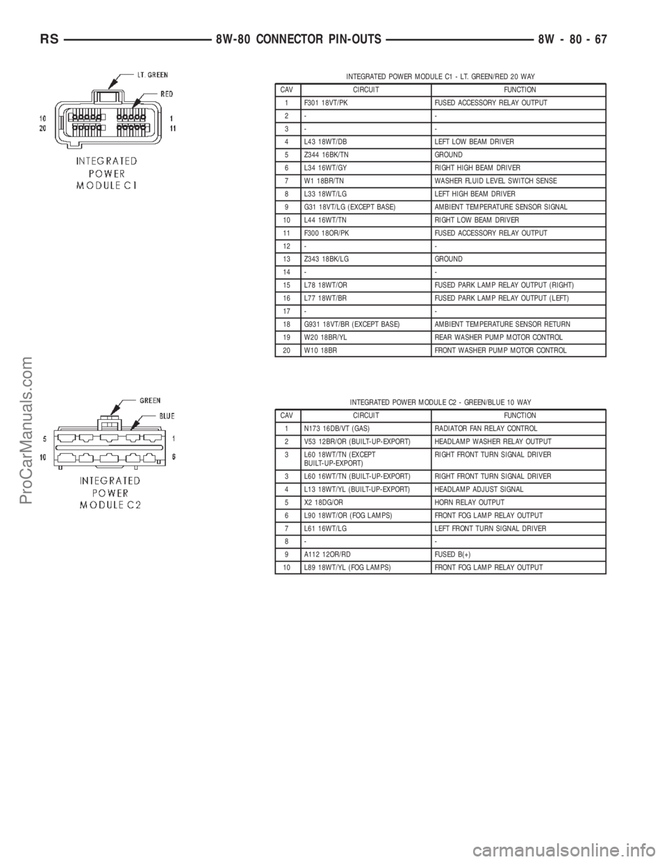
INTEGRATED POWER MODULE C1 - LT. GREEN/RED 20 WAY
CAV CIRCUIT FUNCTION
1 F301 18VT/PK FUSED ACCESSORY RELAY OUTPUT
2- -
3- -
4 L43 18WT/DB LEFT LOW BEAM DRIVER
5 Z344 16BK/TN GROUND
6 L34 16WT/GY RIGHT HIGH BEAM DRIVER
7 W1 18BR/TN WASHER FLUID LEVEL SWITCH SENSE
8 L33 18WT/LG LEFT HIGH BEAM DRIVER
9 G31 18VT/LG (EXCEPT BASE) AMBIENT TEMPERATURE SENSOR SIGNAL
10 L44 16WT/TN RIGHT LOW BEAM DRIVER
11 F300 18OR/PK FUSED ACCESSORY RELAY OUTPUT
12 - -
13 Z343 18BK/LG GROUND
14 - -
15 L78 18WT/OR FUSED PARK LAMP RELAY OUTPUT (RIGHT)
16 L77 18WT/BR FUSED PARK LAMP RELAY OUTPUT (LEFT)
17 - -
18 G931 18VT/BR (EXCEPT BASE) AMBIENT TEMPERATURE SENSOR RETURN
19 W20 18BR/YL REAR WASHER PUMP MOTOR CONTROL
20 W10 18BR FRONT WASHER PUMP MOTOR CONTROL
INTEGRATED POWER MODULE C2 - GREEN/BLUE 10 WAY
CAV CIRCUIT FUNCTION
1 N173 16DB/VT (GAS) RADIATOR FAN RELAY CONTROL
2 V53 12BR/OR (BUILT-UP-EXPORT) HEADLAMP WASHER RELAY OUTPUT
3 L60 18WT/TN (EXCEPT
BUILT-UP-EXPORT)RIGHT FRONT TURN SIGNAL DRIVER
3 L60 16WT/TN (BUILT-UP-EXPORT) RIGHT FRONT TURN SIGNAL DRIVER
4 L13 18WT/YL (BUILT-UP-EXPORT) HEADLAMP ADJUST SIGNAL
5 X2 18DG/OR HORN RELAY OUTPUT
6 L90 18WT/OR (FOG LAMPS) FRONT FOG LAMP RELAY OUTPUT
7 L61 16WT/LG LEFT FRONT TURN SIGNAL DRIVER
8- -
9 A112 12OR/RD FUSED B(+)
10 L89 18WT/YL (FOG LAMPS) FRONT FOG LAMP RELAY OUTPUT
RS8W-80 CONNECTOR PIN-OUTS8W-80-67
ProCarManuals.com
Page 1146 of 2399
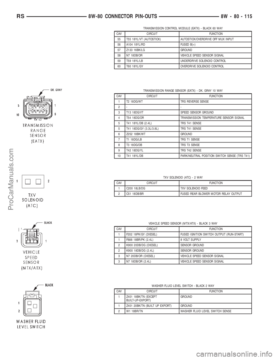
TRANSMISSION CONTROL MODULE (EATX) - BLACK 60 WAY
CAV CIRCUIT FUNCTION
55 T55 18YL/VT (AUTOSTICK) AUTOSTICK/OVERDRIVE OFF MUX INPUT
56 A104 18YL/RD FUSED B(+)
57 Z133 16BK/LG GROUND
58 N7 18DB/OR VEHICLE SPEED SENSOR SIGNAL
59 T59 18YL/LB UNDERDRIVE SOLENOID CONTROL
60 T60 18YL/GY OVERDRIVE SOLENOID CONTROL
TRANSMISSION RANGE SENSOR (EATX) - DK. GRAY 10 WAY
CAV CIRCUIT FUNCTION
1 T2 18DG/WT TRS REVERSE SENSE
2- -
3 T13 18DG/VT SPEED SENSOR GROUND
4 T54 18DG/OR TRANSMISSION TEMPERATURE SENSOR SIGNAL
5 T41 18YL/DB (2.4L) TRS T41 SENSE
5 T41 18DG/GY (3.3L/3.8L) TRS T41 SENSE
6 Z252 18BK/WT GROUND
7 T1 18DG/LB TRS T1 SENSE
8 T3 18DG/DB TRS T3 SENSE
9 T42 18DG/YL TRS T42 SENSE
10 T41 18YL/DB PARK/NEUTRAL POSITION SWITCH SENSE (TRS T41)
TXV SOLENOID (ATC)-2WAY
CAV CIRCUIT FUNCTION
1 C200 18LB/DG TXV SOLENOID FEED
2 C51 18DB/BR FUSED REAR BLOWER MOTOR RELAY OUTPUT
VEHICLE SPEED SENSOR (MTX/ATX) - BLACK 3 WAY
CAV CIRCUIT FUNCTION
1 F202 18PK/GY (DIESEL) FUSED IGNITION SWITCH OUTPUT (RUN-START)
1 F888 18BR/PK (2.4L) 8 VOLT SUPPLY
2 K900 20DB/DG (DIESEL) SENSOR GROUND
2 K900 18DB/DG (2.4L) SENSOR GROUND
3 N7 20DB/OR (DIESEL) VEHICLE SPEED SENSOR SIGNAL
3 N7 18DB/OR (2.4L) VEHICLE SPEED SENSOR SIGNAL
WASHER FLUID LEVEL SWITCH - BLACK 2 WAY
CAV CIRCUIT FUNCTION
1 Z401 18BK/TN (EXCEPT
BUILT-UP-EXPORT)GROUND
1 Z401 20BK/TN (BUILT UP EXPORT) GROUND
2 W1 18BR/TN WASHER FLUID LEVEL SWITCH SENSE
RS8W-80 CONNECTOR PIN-OUTS8W - 80 - 115
ProCarManuals.com
Page 1157 of 2399
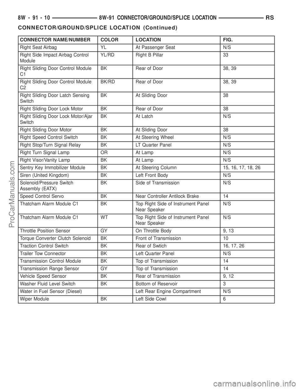
CONNECTOR NAME/NUMBER COLOR LOCATION FIG.
Right Seat Airbag YL At Passenger Seat N/S
Right Side Impact Airbag Control
ModuleYL/RD Right B Pillar 33
Right Sliding Door Control Module
C1BK Rear of Door 38, 39
Right Sliding Door Control Module
C2BK/RD Rear of Door 38, 39
Right Sliding Door Latch Sensing
SwitchBK At Sliding Door 38
Right Sliding Door Lock Motor BK Rear of Door 38
Right Sliding Door Lock Motor/Ajar
SwitchBK At Latch N/S
Right Sliding Door Motor BK At Sliding Door 38
Right Speed Control Switch BK At Steering Wheel N/S
Right Stop/Turn Signal Relay BK LT Quarter Panel N/S
Right Turn Signal Lamp OR At Lamp N/S
Right Visor/Vanity Lamp BK At Lamp N/S
Sentry Key Immobilizer Module BK At Steering Column 15, 16, 17, 18, 26
Siren (United Kingdom) BK Left Front Body N/S
Solenoid/Pressure Switch
Assembly (EATX)BK Side of Transmission N/S
Speed Control Servo BK Near Controller Antilock Brake 14
Thatcham Alarm Module C1 BK Top Right Side of Instrument Panel
Near SpeakerN/S
Thatcham Alarm Module C1 WT Top Right Side of Instrument Panel
Near SpeakerN/S
Throttle Position Sensor GY On Throttle Body 9, 13
Torque Converter Clutch Solenoid BK Front of Transmission 10
Traction Control Switch BK Rear of Swtich 16, 17, 26
Trailer Tow Connector BK Left Quarter Panel N/S
Transmission Control Module BK Top of Transmission 14
Transmission Range Sensor GY Top of Transmission 14
Vehicle Speed Sensor BK Rear of Transmission 9, 12
Washer Fluid Level Switch BK Bottom of Reservoir 3
Water in Fuel Sensor (Diesel) Left Rear Engine Compartment N/S
Wiper Module BK Left Side Cowl 6
8W - 91 - 10 8W-91 CONNECTOR/GROUND/SPLICE LOCATIONRS
CONNECTOR/GROUND/SPLICE LOCATION (Continued)
ProCarManuals.com
Page 1543 of 2399
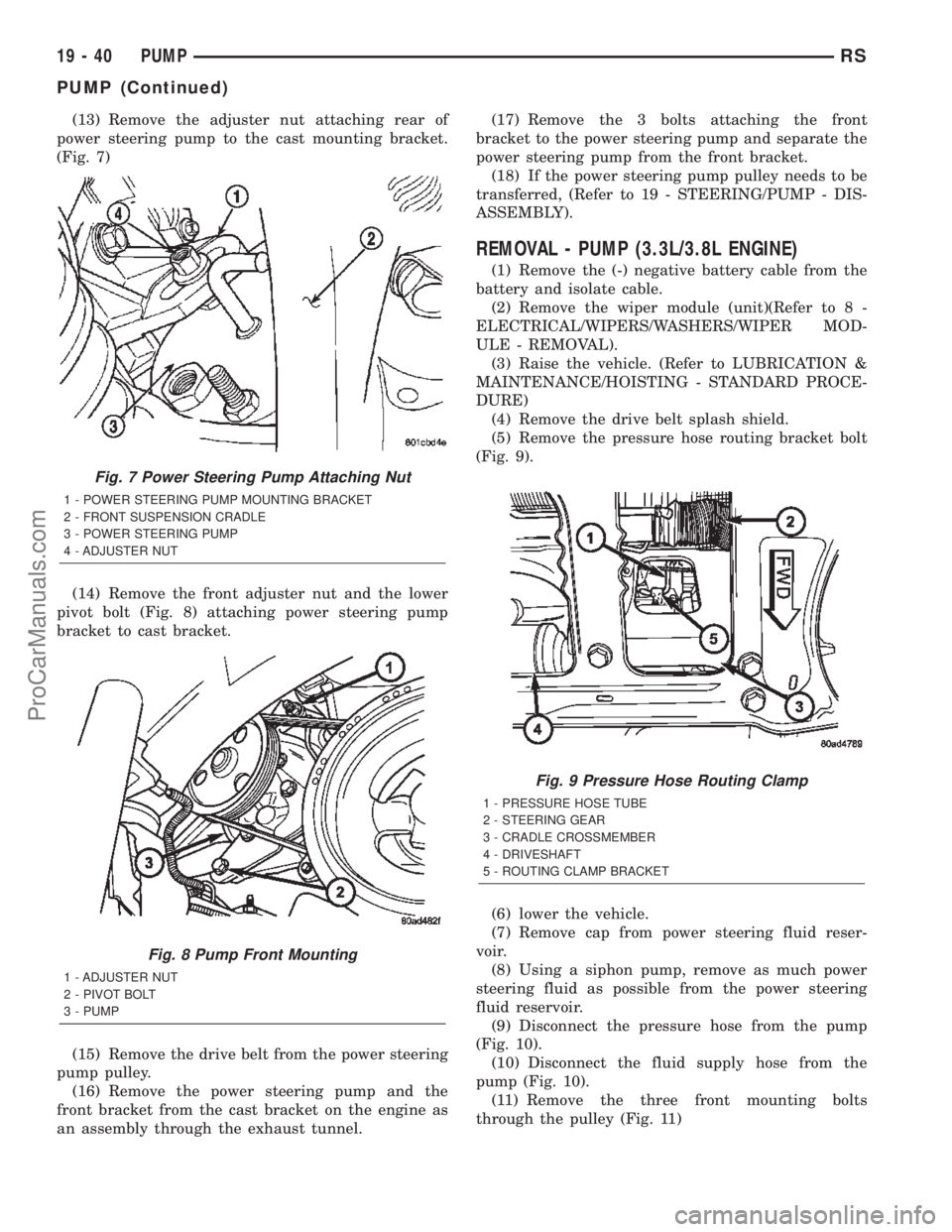
(13) Remove the adjuster nut attaching rear of
power steering pump to the cast mounting bracket.
(Fig. 7)
(14) Remove the front adjuster nut and the lower
pivot bolt (Fig. 8) attaching power steering pump
bracket to cast bracket.
(15) Remove the drive belt from the power steering
pump pulley.
(16) Remove the power steering pump and the
front bracket from the cast bracket on the engine as
an assembly through the exhaust tunnel.(17) Remove the 3 bolts attaching the front
bracket to the power steering pump and separate the
power steering pump from the front bracket.
(18) If the power steering pump pulley needs to be
transferred, (Refer to 19 - STEERING/PUMP - DIS-
ASSEMBLY).
REMOVAL - PUMP (3.3L/3.8L ENGINE)
(1) Remove the (-) negative battery cable from the
battery and isolate cable.
(2) Remove the wiper module (unit)(Refer to 8 -
ELECTRICAL/WIPERS/WASHERS/WIPER MOD-
ULE - REMOVAL).
(3) Raise the vehicle. (Refer to LUBRICATION &
MAINTENANCE/HOISTING - STANDARD PROCE-
DURE)
(4) Remove the drive belt splash shield.
(5) Remove the pressure hose routing bracket bolt
(Fig. 9).
(6) lower the vehicle.
(7) Remove cap from power steering fluid reser-
voir.
(8) Using a siphon pump, remove as much power
steering fluid as possible from the power steering
fluid reservoir.
(9) Disconnect the pressure hose from the pump
(Fig. 10).
(10) Disconnect the fluid supply hose from the
pump (Fig. 10).
(11) Remove the three front mounting bolts
through the pulley (Fig. 11)
Fig. 7 Power Steering Pump Attaching Nut
1 - POWER STEERING PUMP MOUNTING BRACKET
2 - FRONT SUSPENSION CRADLE
3 - POWER STEERING PUMP
4 - ADJUSTER NUT
Fig. 8 Pump Front Mounting
1 - ADJUSTER NUT
2 - PIVOT BOLT
3 - PUMP
Fig. 9 Pressure Hose Routing Clamp
1 - PRESSURE HOSE TUBE
2 - STEERING GEAR
3 - CRADLE CROSSMEMBER
4 - DRIVESHAFT
5 - ROUTING CLAMP BRACKET
19 - 40 PUMPRS
PUMP (Continued)
ProCarManuals.com
Page 1546 of 2399
INSTALLATION
INSTALLATION - PUMP (2.4L ENGINE)
(1) Install power steering pump back in vehicle
using the reverse order of its removal through the
exhaust tunnel of the vehicle.
(2) Install the power steering pump on its cast
mounting bracket (Fig. 7), then install the nut and
bolt attaching the front bracket to the cast bracket
(Fig. 8).Do not fully tighten at this time..
(3) Install the rear nut (Fig. 7).
(4) Install the power steering pump drive belt on
pulley and adjust (Refer to 7 - COOLING/ACCES-
SORY DRIVE/DRIVE BELTS - INSTALLATION).
(5) Tighten the two adjustment slot bolts and the
one pivot bolt to 54 N´m (40 ft. lbs.) torque.
(6) Install the accessory drive splash shield.
NOTE: Before installing power steering fluid pres-
sure hose on power steering pump, inspect the
O-ring on the pressure hose for damage and
replace if necessary.
(7) Install the power steering fluid pressure line
onto the output fitting of the power steering pump
(Fig. 6). Tighten the pressure line to pump fitting
tube nut to a torque of 31 N´m (275 in. lbs.).
(8) Install the power steering fluid low pressure
return hose on the power steering pump low pressure
fitting (Fig. 6).Be sure hose clamps are properly
reinstalled.
(9) Install the power steering fluid supply hose on
the power steering pump fluid fitting.Be sure hose
is clear of accessory drive belts all hose clamps
are properly reinstalled.
CAUTION: Heat sleeve must cover entire rubber
portion of return hose to ensure desired thermal
protection from exhaust.
(10) Properly position the protective heat sleeve
over the power steering return hose. Securely tie
strap the heat sleeve to the power steering hose to
keep in it's proper position.
(11) Install the exhaust system (Fig. 4). Install all
exhaust system isolators/hangers on the exhaust sys-
tem brackets, then the four bolts and flag nuts (Fig.
3).
(12) Connect the oxygen sensor wiring harness to
the vehicle wiring harness.
(13) Lower vehicle.
(14) Connect the negative battery cable on the
negative battery post.
(15) Perform the POWER STEERING PUMP INI-
TIAL OPERATION procedure to properly fill and
bleed the power steering system. (Refer to 19 -
STEERING/PUMP - STANDARD PROCEDURE)(16) Inspect for leaks.
INSTALLATION - PUMP (3.3L/3.8L ENGINE)
(1) Install power steering pump back in vehicle
using the reverse order of its removal through the
engine compartment of the vehicle.
(2) Install the power steering pump on its mount-
ing bracket.
(3) Install the 3 front power steering pump mount-
ing bolts (Fig. 11). Tighten the 3 front power steering
pump mounting bolts to a torque of 54 N´m (40 ft.
lbs.).
NOTE: Before installing power steering pressure
hose on power steering pump, inspect the O-ring
on the power steering pressure hose for damage
and replace if required.
(4) Install the power steering fluid pressure line
into the pressure output fitting of the power steering
pump (Fig. 10).Do not fully tighten tube nut at
this time.
(5) Install the power steering fluid supply hose on
the power steering pump supply fitting (Fig. 10).Be
sure hose clamp is properly installed.
(6) Raise the vehicle.
(7) Install the routing clip on the engine for the
pressure hose (Fig. 9) and tighten fastener.
(8) Install the serpentine drive belt (Refer to 7 -
COOLING/ACCESSORY DRIVE/DRIVE BELTS -
INSTALLATION).
(9) Install the drive belt splash shield.
(10) Lower the vehicle.
(11) Tighten the pressure line to pump pressure
fitting tube nut to a torque of 31 N´m (275 in. lbs.).
(12) Install the wiper module (unit)(Refer to 8 -
ELECTRICAL/WIPERS/WASHERS/WIPER MOD-
ULE - INSTALLATION).
(13) Connect the negative battery cable on the
negative battery post.
(14) Fill and bleed the power steering system
using the Power Steering Pump Initial Operation
Procedure (Refer to 19 - STEERING/PUMP - STAN-
DARD PROCEDURE).
(15) Inspect for leaks.
INSTALLATION - PUMP (2.5L DIESEL)
(1) Install the power steering pump on its cast
mounting bracket.
(2) Install the three front power steering pump
mounting bolts. Tighten the mounting bolts to a
torque of 54 N´m (40 ft. lbs.).
(3) Install the rear mounting bolt fastening the
stamped bracket to the cast bracket (Fig. 13).
Tighten the mounting bolt to a torque of 54 N´m (40
ft. lbs.).
RSPUMP19-43
PUMP (Continued)
ProCarManuals.com
Page 1663 of 2399
mittent, or it takes more than 20 seconds to collect
one quart of fluid, (Refer to 21 - TRANSMISSION/
TRANSAXLE/AUTOMATIC - 31TH - DIAGNOSIS
AND TESTING) for further diagnosis.
(4) Re-connect theTo coolerline to the transmis-
sion cooler inlet using a service splice kit. Refer to
instructions included with the kit.
(5) Refill the transmission to proper level. (Refer
to 21 - TRANSMISSION/TRANSAXLE/AUTOMATIC
- 31TH/FLUID - STANDARD PROCEDURE)
DISASSEMBLY
(1) Remove reaction shaft support-to-pump body
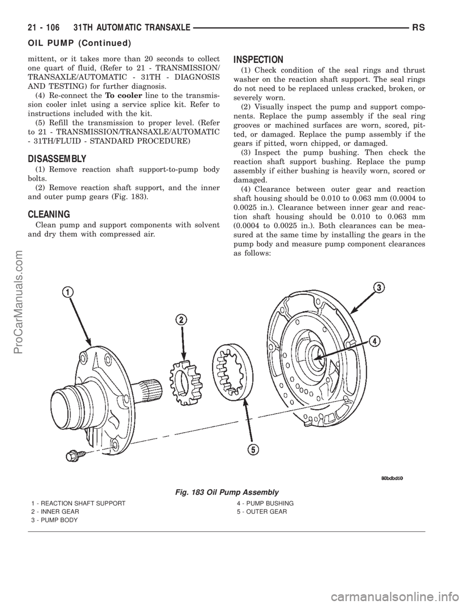
bolts.
(2) Remove reaction shaft support, and the inner
and outer pump gears (Fig. 183).
CLEANING
Clean pump and support components with solvent
and dry them with compressed air.
INSPECTION
(1) Check condition of the seal rings and thrust
washer on the reaction shaft support. The seal rings
do not need to be replaced unless cracked, broken, or
severely worn.
(2) Visually inspect the pump and support compo-
nents. Replace the pump assembly if the seal ring
grooves or machined surfaces are worn, scored, pit-
ted, or damaged. Replace the pump assembly if the
gears if pitted, worn chipped, or damaged.
(3) Inspect the pump bushing. Then check the
reaction shaft support bushing. Replace the pump
assembly if either bushing is heavily worn, scored or
damaged.
(4) Clearance between outer gear and reaction
shaft housing should be 0.010 to 0.063 mm (0.0004 to
0.0025 in.). Clearance between inner gear and reac-
tion shaft housing should be 0.010 to 0.063 mm
(0.0004 to 0.0025 in.). Both clearances can be mea-
sured at the same time by installing the gears in the
pump body and measure pump component clearances
as follows:
Fig. 183 Oil Pump Assembly
1 - REACTION SHAFT SUPPORT
2 - INNER GEAR
3 - PUMP BODY4 - PUMP BUSHING
5 - OUTER GEAR
21 - 106 31TH AUTOMATIC TRANSAXLERS
OIL PUMP (Continued)
ProCarManuals.com
Page 1682 of 2399
STATOR
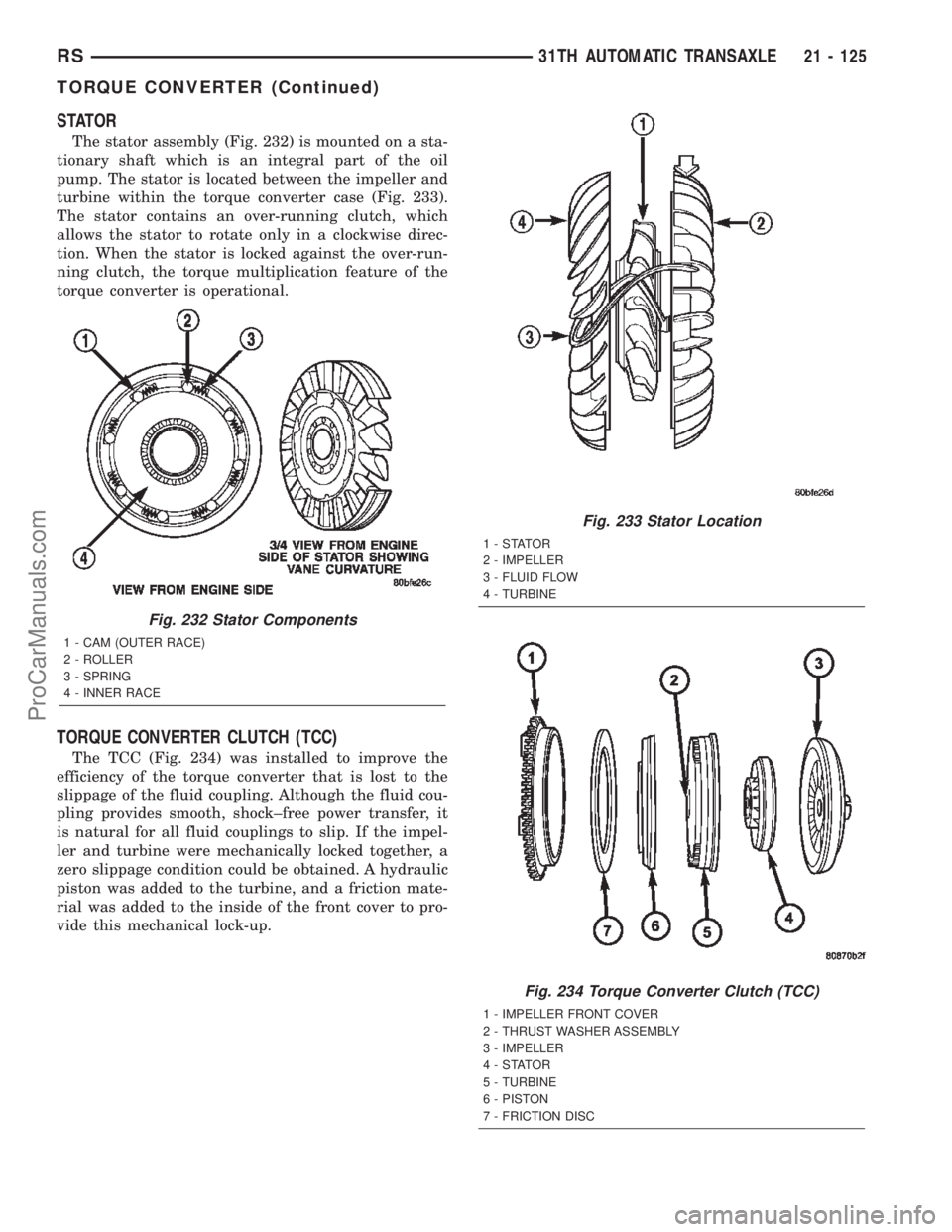
The stator assembly (Fig. 232) is mounted on a sta-
tionary shaft which is an integral part of the oil
pump. The stator is located between the impeller and
turbine within the torque converter case (Fig. 233).
The stator contains an over-running clutch, which
allows the stator to rotate only in a clockwise direc-
tion. When the stator is locked against the over-run-
ning clutch, the torque multiplication feature of the
torque converter is operational.
TORQUE CONVERTER CLUTCH (TCC)
The TCC (Fig. 234) was installed to improve the
efficiency of the torque converter that is lost to the
slippage of the fluid coupling. Although the fluid cou-
pling provides smooth, shock±free power transfer, it
is natural for all fluid couplings to slip. If the impel-
ler and turbine were mechanically locked together, a
zero slippage condition could be obtained. A hydraulic
piston was added to the turbine, and a friction mate-
rial was added to the inside of the front cover to pro-
vide this mechanical lock-up.
Fig. 232 Stator Components
1 - CAM (OUTER RACE)
2 - ROLLER
3 - SPRING
4 - INNER RACE
Fig. 233 Stator Location
1-STATOR
2 - IMPELLER
3 - FLUID FLOW
4 - TURBINE
Fig. 234 Torque Converter Clutch (TCC)
1 - IMPELLER FRONT COVER
2 - THRUST WASHER ASSEMBLY
3 - IMPELLER
4-STATOR
5 - TURBINE
6 - PISTON
7 - FRICTION DISC
RS31TH AUTOMATIC TRANSAXLE21 - 125
TORQUE CONVERTER (Continued)
ProCarManuals.com
Page 1829 of 2399
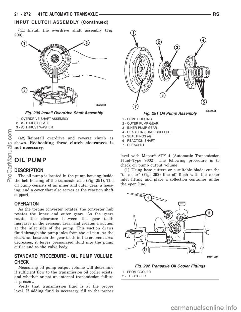
(41) Install the overdrive shaft assembly (Fig.
290).
(42) Reinstall overdrive and reverse clutch as
shown.Rechecking these clutch clearances is
not necessary.
OIL PUMP
DESCRIPTION
The oil pump is located in the pump housing inside
the bell housing of the transaxle case (Fig. 291). The
oil pump consists of an inner and outer gear, a hous-
ing, and a cover that also serves as the reaction shaft
support.
OPERATION
As the torque converter rotates, the converter hub
rotates the inner and outer gears. As the gears
rotate, the clearance between the gear teeth
increases in the crescent area, and creates a suction
at the inlet side of the pump. This suction draws
fluid through the pump inlet from the oil pan. As the
clearance between the gear teeth in the crescent area
decreases, it forces pressurized fluid into the pump
outlet and to the valve body.
STANDARD PROCEDURE - OIL PUMP VOLUME
CHECK
Measuring oil pump output volume will determine
if sufficient flow to the transmission oil cooler exists,
and whether or not an internal transmission failure
is present.
Verify that transmission fluid is at the proper
level. If adding fluid is necessary, fill to the properlevel with MopartATF+4 (Automatic Transmission
Fluid±Type 9602). The following procedure is to
check oil pump output volume:
(1) Using hose cutters or a suitable blade, cut the
ªto coolerº (Fig. 292) line off flush with the cooler
inlet fitting and place a collection container under
the open line.
Fig. 290 Install Overdrive Shaft Assembly
1 - OVERDRIVE SHAFT ASSEMBLY
2 - #3 THRUST PLATE
3 - #3 THRUST WASHER
Fig. 291 Oil Pump Assembly
1 - PUMP HOUSING
2 - OUTER PUMP GEAR
3 - INNER PUMP GEAR
4 - REACTION SHAFT SUPPORT
5 - SEAL RINGS (4)
6 - REACTION SHAFT
7 - CRESCENT
Fig. 292 Transaxle Oil Cooler Fittings
1 - FROM COOLER
2 - TO COOLER
21 - 272 41TE AUTOMATIC TRANSAXLERS
INPUT CLUTCH ASSEMBLY (Continued)
ProCarManuals.com