2002 CHRYSLER CARAVAN recommended oil
[x] Cancel search: recommended oilPage 1807 of 2399
(6) Adjust transmission fluid level shown on the
indicator according to the chart.
(7) Check transmission for leaks.
Low fluid level can cause a variety of conditions
because it allows the pump to take in air along with
the fluid. As in any hydraulic system, air bubbles
make the fluid spongy, therefore, pressures will be
low and build up slowly.
Improper filling can also raise the fluid level too
high. When the transaxle has too much fluid, the
gears churn up foam and cause the same conditions
which occur with a low fluid level.
In either case, air bubbles can cause overheating
and/or fluid oxidation, and varnishing. This can
interfere with normal valve, clutch, and accumulator
operation. Foaming can also result in fluid escaping
from the transaxle vent where it may be mistaken
for a leak.
FLUID CONDITION
Along with fluid level, it is important to check the
condition of the fluid. When the fluid smells burned,
and is contaminated with metal or friction material
particles, a complete transaxle recondition is proba-
bly required. Be sure to examine the fluid on the dip-
stick closely. If there is any doubt about its condition,
drain out a sample for a double check.
MopartATF+4 (Automatic Transmission Fluid-
Type 9602) when new is red in color. The ATF is dyed
red so it can be identified from other fluids used in
the vehicle such as engine oil or antifreeze. The red
color is not permanent and is not an indicator of fluid
condition. As the vehicle is driven, the ATF will begin
to look darker in color and may eventually become
brown.This is normal.ATF+4 also has a unique
odor that may change with age. Consequently,odor
and color cannot be used to indicate the fluid
condition or the need for a fluid change.
After the fluid has been checked, seat the dipstick
fully to seal out water and dirt.
STANDARD PROCEDURE - FLUID AND FILTER
SERVICE
NOTE: Refer to the maintenance schedules in
LUBRICATION and MAINTENANCE, or the vehicle
owner's manual, for the recommended maintenance
(fluid/filter change) intervals for this transaxle.
NOTE: Only fluids of the type labeled MoparTATF+4
(Automatic Transmission Fluid) Type 9602 should
be used. A filter change should be made at the time
of the transmission oil change. The magnet (on the
inside of the oil pan) should also be cleaned with a
clean, dry cloth.NOTE: If the transaxle is disassembled for any rea-
son, the fluid and filter should be changed.
FLUID/FILTER SERVICE (RECOMMENDED)
(1) Raise vehicle on a hoist. Refer to LUBRICA-
TION and MAINTENANCE for proper procedures.
Place a drain container with a large opening, under
transaxle oil pan.
(2) Loosen pan bolts and tap the pan at one corner
to break it loose allowing fluid to drain, then remove
the oil pan.
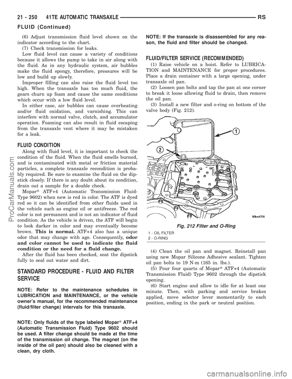
(3) Install a new filter and o-ring on bottom of the
valve body (Fig. 212).
(4) Clean the oil pan and magnet. Reinstall pan
using new Mopar Silicone Adhesive sealant. Tighten
oil pan bolts to 19 N´m (165 in. lbs.).
(5) Pour four quarts of MopartATF+4 (Automatic
Transmission Fluid) Type 9602 through the dipstick
opening.
(6) Start engine and allow to idle for at least one
minute. Then, with parking and service brakes
applied, move selector lever momentarily to each
position, ending in the park or neutral position.
Fig. 212 Filter and O-Ring
1 - OIL FILTER
2 - O-RING
21 - 250 41TE AUTOMATIC TRANSAXLERS
FLUID (Continued)
ProCarManuals.com
Page 1808 of 2399
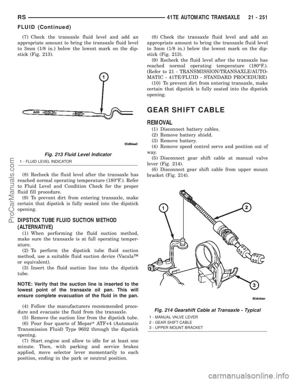
(7) Check the transaxle fluid level and add an
appropriate amount to bring the transaxle fluid level
to 3mm (1/8 in.) below the lowest mark on the dip-
stick (Fig. 213).
(8) Recheck the fluid level after the transaxle has
reached normal operating temperature (180ÉF.). Refer
to Fluid Level and Condition Check for the proper
fluid fill procedure.
(9) To prevent dirt from entering transaxle, make
certain that dipstick is fully seated into the dipstick
opening.
DIPSTICK TUBE FLUID SUCTION METHOD
(ALTERNATIVE)
(1) When performing the fluid suction method,
make sure the transaxle is at full operating temper-
ature.
(2) To perform the dipstick tube fluid suction
method, use a suitable fluid suction device (VaculaŸ
or equivalent).
(3) Insert the fluid suction line into the dipstick
tube.
NOTE: Verify that the suction line is inserted to the
lowest point of the transaxle oil pan. This will
ensure complete evacuation of the fluid in the pan.
(4) Follow the manufacturers recommended proce-
dure and evacuate the fluid from the transaxle.
(5) Remove the suction line from the dipstick tube.
(6) Pour four quarts of MopartATF+4 (Automatic
Transmission Fluid) Type 9602 through the dipstick
opening.
(7) Start engine and allow to idle for at least one
minute. Then, with parking and service brakes
applied, move selector lever momentarily to each
position, ending in the park or neutral position.(8) Check the transaxle fluid level and add an
appropriate amount to bring the transaxle fluid level
to 3mm (1/8 in.) below the lowest mark on the dip-
stick (Fig. 213).
(9) Recheck the fluid level after the transaxle has
reached normal operating temperature (180ÉF.).
(Refer to 21 - TRANSMISSION/TRANSAXLE/AUTO-
MATIC - 41TE/FLUID - STANDARD PROCEDURE)
(10) To prevent dirt from entering transaxle, make
certain that dipstick is fully seated into the dipstick
opening.
GEAR SHIFT CABLE
REMOVAL
(1) Disconnect battery cables.
(2) Remove battery shield.
(3) Remove battery.
(4) Remove speed control servo and position out of
way.
(5) Disconnect gear shift cable at manual valve
lever (Fig. 214).
(6) Disconnect gear shift cable from upper mount
bracket (Fig. 214).
Fig. 213 Fluid Level Indicator
1 - FLUID LEVEL INDICATOR
Fig. 214 Gearshift Cable at Transaxle - Typical
1 - MANUAL VALVE LEVER
2 - GEAR SHIFT CABLE
3 - UPPER MOUNT BRACKET
RS41TE AUTOMATIC TRANSAXLE21 - 251
FLUID (Continued)
ProCarManuals.com
Page 1847 of 2399
clutch is engaged by the clutch solenoid on the valve
body. The clutch will engage at approximately 56
km/h (35 mph) with light throttle, after the shift to
third gear.
REMOVAL
(1) Remove transmission and torque converter
from vehicle. (Refer to 21 - TRANSMISSION/TRANS-
AXLE/AUTOMATIC - 41TE - REMOVAL)
(2) Place a suitable drain pan under the converter
housing end of the transmission.
CAUTION: Verify that transmission is secure on the
lifting device or work surface, the center of gravity
of the transmission will shift when the torque con-
verter is removed creating an unstable condition.
The torque converter is a heavy unit. Use caution
when separating the torque converter from the
transmission.
(3) Pull the torque converter forward until the cen-
ter hub clears the oil pump seal.
(4) Separate the torque converter from the trans-
mission.
INSTALLATION
Check converter hub and drive notches for sharp
edges, burrs, scratches, or nicks. Polish the hub and
notches with 320/400 grit paper or crocus cloth if nec-
essary. The hub must be smooth to avoid damaging
the pump seal at installation.
(1) Lubricate converter hub and oil pump seal lip
with transmission fluid.(2) Place torque converter in position on transmis-
sion.
CAUTION: Do not damage oil pump seal or bushing
while inserting torque converter into the front of the
transmission.
(3) Align torque converter to oil pump seal open-
ing.
(4) Insert torque converter hub into oil pump.
(5) While pushing torque converter inward, rotate
converter until converter is fully seated in the oil
pump gears.
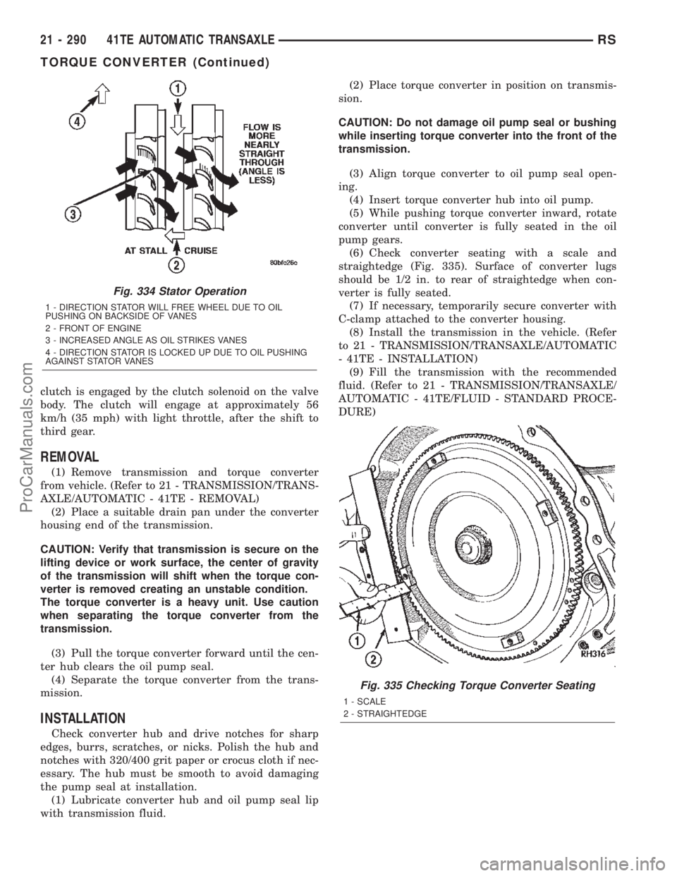
(6) Check converter seating with a scale and
straightedge (Fig. 335). Surface of converter lugs
should be 1/2 in. to rear of straightedge when con-
verter is fully seated.
(7) If necessary, temporarily secure converter with
C-clamp attached to the converter housing.
(8) Install the transmission in the vehicle. (Refer
to 21 - TRANSMISSION/TRANSAXLE/AUTOMATIC
- 41TE - INSTALLATION)
(9) Fill the transmission with the recommended
fluid. (Refer to 21 - TRANSMISSION/TRANSAXLE/
AUTOMATIC - 41TE/FLUID - STANDARD PROCE-
DURE)
Fig. 334 Stator Operation
1 - DIRECTION STATOR WILL FREE WHEEL DUE TO OIL
PUSHING ON BACKSIDE OF VANES
2 - FRONT OF ENGINE
3 - INCREASED ANGLE AS OIL STRIKES VANES
4 - DIRECTION STATOR IS LOCKED UP DUE TO OIL PUSHING
AGAINST STATOR VANES
Fig. 335 Checking Torque Converter Seating
1 - SCALE
2 - STRAIGHTEDGE
21 - 290 41TE AUTOMATIC TRANSAXLERS
TORQUE CONVERTER (Continued)
ProCarManuals.com
Page 2303 of 2399
PLUMBING - FRONT
WARNING
WARNING
WARNING: DO NOT OPERATE DCHA IN AN
ENCLOSED AREA SUCH AS A GARAGE THAT
DOES NOT HAVE EXHAUST VENTILATION FACILI-
TIES. ALWAYS VENT THE DCHA'S EXHAUST WHEN
OPERATING THE DCHA. FAILURE TO FOLLOW
THESE INSTRUCTION MAY RESULT IN PERSONAL
INJURY OR DEATH.
ALLOW THE DCHA ASSEMBLY TO COOL BEFORE
PERFORMING A COMPONENT INSPECTION/RE-
PAIR/REPLACEMENT. FAILURE TO FOLLOW THESE
INSTRUCTIONS MY RESULT IN PERSONAL INJURY.
VERIFY THAT ALL DCHA FUEL LINES ARE
SECURELY FASTENED TO THEIR RESPECTIVE
COMPONENTS BEFORE THIS PROCEDURE.
WARNING
WARNING:: THE ENGINE COOLING SYSTEM IS
DESIGNED TO DEVELOP INTERNAL PRESSURES
OF 97 TO 123 KILOPASCALS (14 TO 18 POUNDS
PER SQUARE INCH). DO NOT REMOVE OR
LOOSEN THE COOLANT PRESSURE CAP, CYLIN-
DER BLOCK DRAIN PLUGS, RADIATOR DRAIN,
RADIATOR HOSES, HEATER HOSES, OR HOSE
CLAMPS WHILE THE SYSTEM IS HOT AND UNDER
PRESSURE. FAILURE TO OBSERVE THIS WARNING
CAN RESULT IN SERIOUS BURNS FROM THE
HEATED ENGINE COOLANT. ALLOW THE VEHICLE
TO COOL FOR A MINIMUM OF 15 MINUTES
BEFORE OPENING THE COOLING SYSTEM FOR
SERVICE.
WARNING: THE ENGINE COOLING SYSTEM CON-
TAINS ANTIFREEZE. ANTIFREEZE IS AN ETHYLENE
GLYCOL BASED COOLANT AND IS HARMFUL IF
SWALLOWED OR IF THE VAPORS ARE INHALED. IF
SWALLOWED, DRINK TWO GLASSES OF WATER
AND INDUCE VOMITING. IF VAPORS ARE INHALED,
MOVE TO AN AREA FOR FRESH AIR. SEEK MEDI-
CAL ATTENTION IMMEDIATELY. DO NOT STORE IN
OPEN OR UNMARKED CONTAINERS. WASH SKIN
AND CLOTHING THOROUGHLY AFTER COMING IN
CONTACT WITH ETHYLENE GLYCOL. KEEP OUT
OF REACH OF CHILDREN.
WARNING: DISPOSE OF ETHYLENE GLYCOL
BASED COOLANT PROPERLY. CONTACT YOURDEALER OR A LOCAL GOVERNMENT AGENCY FOR
THE LOCATION OF AN APPROVED ETHYLENE GLY-
COL COLLECTION AND/OR RECYCLING CENTER IN
YOUR AREA.
WARNING - A/C PLUMBING
WARNING:: THE AIR CONDITIONING SYSTEM CON-
TAINS REFRIGERANT UNDER HIGH PRESSURE.
SEVERE PERSONAL INJURY MAY RESULT FROM
IMPROPER SERVICE PROCEDURES. REPAIRS
SHOULD ONLY BE PERFORMED BY QUALIFIED
SERVICE PERSONNEL.
WARNING: AVOID BREATHING THE REFRIGERANT
AND REFRIGERANT OIL VAPOR OR MIST. EXPO-
SURE MAY IRRITATE THE EYES, NOSE, AND/OR
THROAT. WEAR EYE PROTECTION WHEN SERVIC-
ING THE AIR CONDITIONING REFRIGERANT SYS-
TEM. SERIOUS EYE INJURY CAN RESULT FROM
DIRECT CONTACT WITH THE REFRIGERANT. IF
EYE CONTACT OCCURS, SEEK MEDICAL ATTEN-
TION IMMEDIATELY.
WARNING: DO NOT EXPOSE THE REFRIGERANT
TO OPEN FLAME. POISONOUS GAS IS CREATED
WHEN REFRIGERANT IS BURNED. AN ELEC-
TRONIC LEAK DETECTOR IS RECOMMENDED.
WARNING: IF ACCIDENTAL SYSTEM DISCHARGE
OCCURS, VENTILATE THE WORK AREA BEFORE
RESUMING SERVICE. LARGE AMOUNTS OF
REFRIGERANT RELEASED IN A CLOSED WORK
AREA WILL DISPLACE THE OXYGEN AND CAUSE
SUFFOCATION.
WARNING: THE EVAPORATION RATE OF R-134a
REFRIGERANT AT AVERAGE TEMPERATURE AND
ALTITUDE IS EXTREMELY HIGH. AS A RESULT,
ANYTHING THAT COMES IN CONTACT WITH THE
REFRIGERANT WILL FREEZE. ALWAYS PROTECT
THE SKIN OR DELICATE OBJECTS FROM DIRECT
CONTACT WITH THE REFRIGERANT.
WARNING: THE R-134a SERVICE EQUIPMENT OR
THE VEHICLE REFRIGERANT SYSTEM SHOULD
NOT BE PRESSURE TESTED OR LEAK TESTED
WITH COMPRESSED AIR. SOME MIXTURES OF AIR
AND R-134a HAVE BEEN SHOWN TO BE COMBUS-
TIBLE AT ELEVATED PRESSURES. THESE MIX-
TURES ARE POTENTIALLY DANGEROUS, AND MAY
RESULT IN FIRE OR EXPLOSION CAUSING INJURY
OR PROPERTY DAMAGE.
24 - 60 PLUMBING - FRONTRS
ProCarManuals.com
Page 2307 of 2399
(17) Remove the compressor from the engine com-
partment.
NOTE: If a replacement compressor is being
installed, be certain to drain and measure the refrig-
erant oil contained in the removed compressor.
This will determine how much oil the replacement
compressor must contain before it is installed.
(Refer to 24 - HEATING & AIR CONDITIONING/
PLUMBING - FRONT/REFRIGERANT OIL - STAN-
DARD PROCEDURE - REFRIGERANT OIL LEVEL).
REMOVAL - COMPRESSOR MOUNTING
BRACKET - 2.4L ENGINE
(1) Remove the compressor from the mounting
bracket. (Refer to 24 - HEATING & AIR CONDI-
TIONING/PLUMBING/COMPRESSOR - REMOVAL).
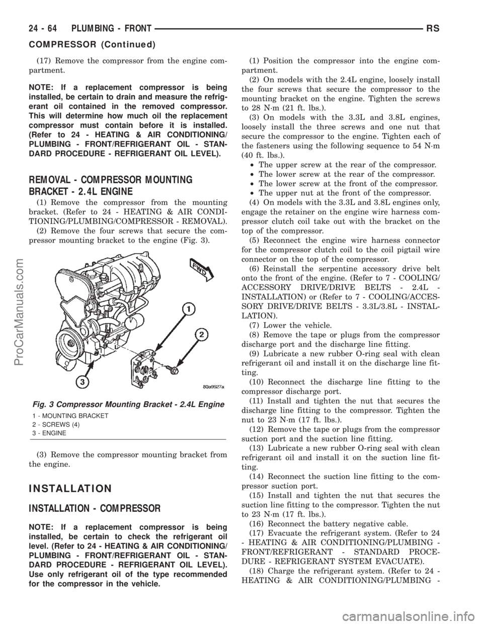
(2) Remove the four screws that secure the com-
pressor mounting bracket to the engine (Fig. 3).
(3) Remove the compressor mounting bracket from
the engine.
INSTALLATION
INSTALLATION - COMPRESSOR
NOTE: If a replacement compressor is being
installed, be certain to check the refrigerant oil
level. (Refer to 24 - HEATING & AIR CONDITIONING/
PLUMBING - FRONT/REFRIGERANT OIL - STAN-
DARD PROCEDURE - REFRIGERANT OIL LEVEL).
Use only refrigerant oil of the type recommended
for the compressor in the vehicle.(1) Position the compressor into the engine com-
partment.
(2) On models with the 2.4L engine, loosely install
the four screws that secure the compressor to the
mounting bracket on the engine. Tighten the screws
to 28 N´m (21 ft. lbs.).
(3) On models with the 3.3L and 3.8L engines,
loosely install the three screws and one nut that
secure the compressor to the engine. Tighten each of
the fasteners using the following sequence to 54 N´m
(40 ft. lbs.).
²The upper screw at the rear of the compressor.
²The lower screw at the rear of the compressor.
²The lower screw at the front of the compressor.
²The upper nut at the front of the compressor.
(4) On models with the 3.3L and 3.8L engines only,
engage the retainer on the engine wire harness com-
pressor clutch coil take out with the bracket on the
top of the compressor.
(5) Reconnect the engine wire harness connector
for the compressor clutch coil to the coil pigtail wire
connector on the top of the compressor.
(6) Reinstall the serpentine accessory drive belt
onto the front of the engine. (Refer to 7 - COOLING/
ACCESSORY DRIVE/DRIVE BELTS - 2.4L -
INSTALLATION) or (Refer to 7 - COOLING/ACCES-
SORY DRIVE/DRIVE BELTS - 3.3L/3.8L - INSTAL-
LATION).
(7) Lower the vehicle.
(8) Remove the tape or plugs from the compressor
discharge port and the discharge line fitting.
(9) Lubricate a new rubber O-ring seal with clean
refrigerant oil and install it on the discharge line fit-
ting.
(10) Reconnect the discharge line fitting to the
compressor discharge port.
(11) Install and tighten the nut that secures the
discharge line fitting to the compressor. Tighten the
nut to 23 N´m (17 ft. lbs.).
(12) Remove the tape or plugs from the compressor
suction port and the suction line fitting.
(13) Lubricate a new rubber O-ring seal with clean
refrigerant oil and install it on the suction line fit-
ting.
(14) Reconnect the suction line fitting to the com-
pressor suction port.
(15) Install and tighten the nut that secures the
suction line fitting to the compressor. Tighten the nut
to 23 N´m (17 ft. lbs.).
(16) Reconnect the battery negative cable.
(17) Evacuate the refrigerant system. (Refer to 24
- HEATING & AIR CONDITIONING/PLUMBING -
FRONT/REFRIGERANT - STANDARD PROCE-
DURE - REFRIGERANT SYSTEM EVACUATE).
(18) Charge the refrigerant system. (Refer to 24 -
HEATING & AIR CONDITIONING/PLUMBING -
Fig. 3 Compressor Mounting Bracket - 2.4L Engine
1 - MOUNTING BRACKET
2 - SCREWS (4)
3 - ENGINE
24 - 64 PLUMBING - FRONTRS
COMPRESSOR (Continued)
ProCarManuals.com
Page 2309 of 2399
(8) Disconnect the discharge line fitting from the
condenser inlet port.
(9) Remove the seal from the discharge line fitting
and discard.
(10) Install plugs in, or tape over the opened dis-
charge line fitting and the condenser inlet port.
(11) Remove the nut that secures the liquid line
fitting to the condenser on the right side of the cool-
ing module.
(12) Disconnect the liquid line fitting from the con-
denser outlet port.
(13) Remove the seal from the liquid line fitting
and discard.
(14) Install plugs in, or tape over the opened liquid
line fitting and the condenser outlet port.
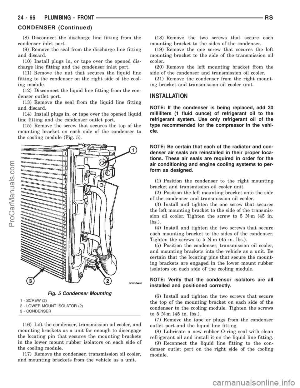
(15) Remove the screw that secures the top of the
mounting bracket on each side of the condenser to
the cooling module (Fig. 5).
(16) Lift the condenser, transmission oil cooler, and
mounting brackets as a unit far enough to disengage
the locating pin that secures the mounting brackets
in the lower mount rubber isolators on each side of
the cooling module.
(17) Remove the condenser, transmission oil cooler,
and mounting brackets from the vehicle as a unit.(18) Remove the two screws that secure each
mounting bracket to the sides of the condenser.
(19) Remove the one screw that secures the left
mounting bracket to the side of the transmission oil
cooler.
(20) Remove the left mounting bracket from the
side of the condenser and transmission oil cooler.
(21) Remove the condenser from the right mount-
ing bracket and transmission oil cooler unit.
INSTALLATION
NOTE: If the condenser is being replaced, add 30
milliliters (1 fluid ounce) of refrigerant oil to the
refrigerant system. Use only refrigerant oil of the
type recommended for the compressor in the vehi-
cle.
NOTE: Be certain that each of the radiator and con-
denser air seals are reinstalled in their proper loca-
tions. These air seals are required in order for the
air conditioning and engine cooling systems to per-
form as designed.
(1) Position the condenser to the right mounting
bracket and transmission oil cooler unit.
(2) Position the left mounting bracket onto the side
of the condenser and transmission oil cooler.
(3) Install and tighten the one screw that secures
the left mounting bracket to the side of the transmis-
sion oil cooler. Tighten the screw to 5 N´m (45 in.
lbs.).
(4) Install and tighten the two screws that secure
each mounting bracket to the sides of the condenser.
Tighten the screws to 5 N´m (45 in. lbs.).
(5) Position the condenser, transmission oil cooler,
and mounting brackets into the vehicle as a unit. Be
certain that the locating pins that secure the mount-
ing brackets are engaged in the lower mount rubber
isolators on each side of the cooling module.
NOTE: Verify that the condensor isolators are all
installed and positioned correctly.
(6) Install and tighten the two screws that secure
the top of the mounting bracket on each side of the
condenser to the cooling module. Tighten the screws
to 5 N´m (45 in. lbs.).
(7) Remove the tape or plugs from the condenser
outlet port and the liquid line fitting.
(8) Lubricate a new rubber O-ring seal with clean
refrigerant oil and install it on the liquid line fitting.
(9) Reconnect the liquid line fitting to the con-
denser outlet port on the right side of the cooling
module.
Fig. 5 Condenser Mounting
1 - SCREW (2)
2 - LOWER MOUNT ISOLATOR (2)
3 - CONDENSER
24 - 66 PLUMBING - FRONTRS
CONDENSER (Continued)
ProCarManuals.com
Page 2313 of 2399
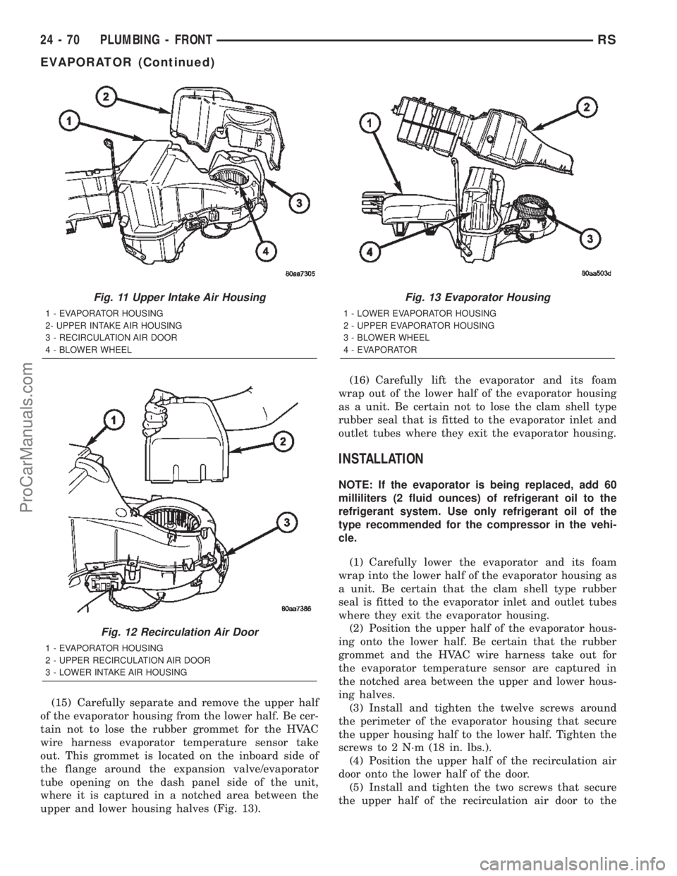
(15) Carefully separate and remove the upper half
of the evaporator housing from the lower half. Be cer-
tain not to lose the rubber grommet for the HVAC
wire harness evaporator temperature sensor take
out. This grommet is located on the inboard side of
the flange around the expansion valve/evaporator
tube opening on the dash panel side of the unit,
where it is captured in a notched area between the
upper and lower housing halves (Fig. 13).(16) Carefully lift the evaporator and its foam
wrap out of the lower half of the evaporator housing
as a unit. Be certain not to lose the clam shell type
rubber seal that is fitted to the evaporator inlet and
outlet tubes where they exit the evaporator housing.
INSTALLATION
NOTE: If the evaporator is being replaced, add 60
milliliters (2 fluid ounces) of refrigerant oil to the
refrigerant system. Use only refrigerant oil of the
type recommended for the compressor in the vehi-
cle.
(1) Carefully lower the evaporator and its foam
wrap into the lower half of the evaporator housing as
a unit. Be certain that the clam shell type rubber
seal is fitted to the evaporator inlet and outlet tubes
where they exit the evaporator housing.
(2) Position the upper half of the evaporator hous-
ing onto the lower half. Be certain that the rubber
grommet and the HVAC wire harness take out for
the evaporator temperature sensor are captured in
the notched area between the upper and lower hous-
ing halves.
(3) Install and tighten the twelve screws around
the perimeter of the evaporator housing that secure
the upper housing half to the lower half. Tighten the
screws to 2 N´m (18 in. lbs.).
(4) Position the upper half of the recirculation air
door onto the lower half of the door.
(5) Install and tighten the two screws that secure
the upper half of the recirculation air door to the
Fig. 11 Upper Intake Air Housing
1 - EVAPORATOR HOUSING
2- UPPER INTAKE AIR HOUSING
3 - RECIRCULATION AIR DOOR
4 - BLOWER WHEEL
Fig. 12 Recirculation Air Door
1 - EVAPORATOR HOUSING
2 - UPPER RECIRCULATION AIR DOOR
3 - LOWER INTAKE AIR HOUSING
Fig. 13 Evaporator Housing
1 - LOWER EVAPORATOR HOUSING
2 - UPPER EVAPORATOR HOUSING
3 - BLOWER WHEEL
4 - EVAPORATOR
24 - 70 PLUMBING - FRONTRS
EVAPORATOR (Continued)
ProCarManuals.com
Page 2329 of 2399
(1) Recover the refrigerant from the refrigerant
system. (Refer to 24 - HEATING & AIR CONDI-
TIONING/PLUMBING - FRONT/REFRIGERANT -
STANDARD PROCEDURE - REFRIGERANT
RECOVERY).
(2) Remove the air cleaner housing from the right
side of the engine compartment.
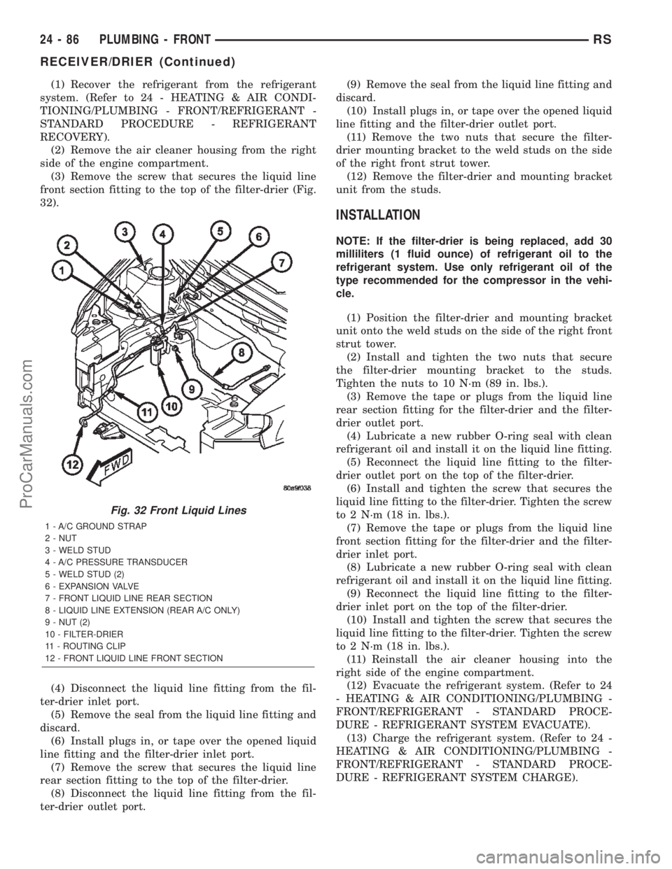
(3) Remove the screw that secures the liquid line
front section fitting to the top of the filter-drier (Fig.
32).
(4) Disconnect the liquid line fitting from the fil-
ter-drier inlet port.
(5) Remove the seal from the liquid line fitting and
discard.
(6) Install plugs in, or tape over the opened liquid
line fitting and the filter-drier inlet port.
(7) Remove the screw that secures the liquid line
rear section fitting to the top of the filter-drier.
(8) Disconnect the liquid line fitting from the fil-
ter-drier outlet port.(9) Remove the seal from the liquid line fitting and
discard.
(10) Install plugs in, or tape over the opened liquid
line fitting and the filter-drier outlet port.
(11) Remove the two nuts that secure the filter-
drier mounting bracket to the weld studs on the side
of the right front strut tower.
(12) Remove the filter-drier and mounting bracket
unit from the studs.
INSTALLATION
NOTE: If the filter-drier is being replaced, add 30
milliliters (1 fluid ounce) of refrigerant oil to the
refrigerant system. Use only refrigerant oil of the
type recommended for the compressor in the vehi-
cle.
(1) Position the filter-drier and mounting bracket
unit onto the weld studs on the side of the right front
strut tower.
(2) Install and tighten the two nuts that secure
the filter-drier mounting bracket to the studs.
Tighten the nuts to 10 N´m (89 in. lbs.).
(3) Remove the tape or plugs from the liquid line
rear section fitting for the filter-drier and the filter-
drier outlet port.
(4) Lubricate a new rubber O-ring seal with clean
refrigerant oil and install it on the liquid line fitting.
(5) Reconnect the liquid line fitting to the filter-
drier outlet port on the top of the filter-drier.
(6) Install and tighten the screw that secures the
liquid line fitting to the filter-drier. Tighten the screw
to 2 N´m (18 in. lbs.).
(7) Remove the tape or plugs from the liquid line
front section fitting for the filter-drier and the filter-
drier inlet port.
(8) Lubricate a new rubber O-ring seal with clean
refrigerant oil and install it on the liquid line fitting.
(9) Reconnect the liquid line fitting to the filter-
drier inlet port on the top of the filter-drier.
(10) Install and tighten the screw that secures the
liquid line fitting to the filter-drier. Tighten the screw
to 2 N´m (18 in. lbs.).
(11) Reinstall the air cleaner housing into the
right side of the engine compartment.
(12) Evacuate the refrigerant system. (Refer to 24
- HEATING & AIR CONDITIONING/PLUMBING -
FRONT/REFRIGERANT - STANDARD PROCE-
DURE - REFRIGERANT SYSTEM EVACUATE).
(13) Charge the refrigerant system. (Refer to 24 -
HEATING & AIR CONDITIONING/PLUMBING -
FRONT/REFRIGERANT - STANDARD PROCE-
DURE - REFRIGERANT SYSTEM CHARGE).
Fig. 32 Front Liquid Lines
1 - A/C GROUND STRAP
2 - NUT
3 - WELD STUD
4 - A/C PRESSURE TRANSDUCER
5 - WELD STUD (2)
6 - EXPANSION VALVE
7 - FRONT LIQUID LINE REAR SECTION
8 - LIQUID LINE EXTENSION (REAR A/C ONLY)
9 - NUT (2)
10 - FILTER-DRIER
11 - ROUTING CLIP
12 - FRONT LIQUID LINE FRONT SECTION
24 - 86 PLUMBING - FRONTRS
RECEIVER/DRIER (Continued)
ProCarManuals.com