Page 1603 of 2399
(23) Remove park sprag rod support-to-case bolts
(Fig. 37).
(24) Remove support and bolts (Fig. 38).
NOTE: To remove pawl, spring, and pivot shaft, the
governor support retainer must be removed. (Refer
to 21 - TRANSMISSION/TRANSAXLE/AUTOMATIC -
31TH/TRANSFER SYSTEM - REMOVAL)(25) Remove park pawl, spring, and pivot shaft
(Fig. 39).
(26) Remove oil pump-to-transaxle case bolts (Fig.
40).
Fig. 37 Parking Sprag Rod Support
1 - PARKING SPRAG ROD SUPPORT
2 - BOLT (2)
3 - OUTPUT SHAFT GEAR
Fig. 38 Support and Bolts
1 - BOLT (2)
2 - PARKING SPRAG ROD SUPPORT
Fig. 39 Parking Pawl, Return Spring, and Pivot Shaft
1 - PARK PAWL
2 - RETURN SPRING
3 - NOTE: SMALL DIAMETER TO REAR
4 - PIVOT SHAFT
Fig. 40 Oil Pump Attaching Bolts
1 - SEAL
2 - PUMP ATTACHING BOLTS (7)
3 - PUMP HOUSING
21 - 46 31TH AUTOMATIC TRANSAXLERS
31TH AUTOMATIC TRANSAXLE (Continued)
ProCarManuals.com
Page 1604 of 2399
(27) Install Tool C-3752 and adapters L-4437 as
shown in (Fig. 41).
(28) Remove oil pump with slide hammer setup
(Fig. 42). Inspect #1 thrust washer.(29) Remove oil pump gasket (Fig. 43).
(30) Remove kickdown band and strut (Fig. 44).
Fig. 41 Install Tool C-3752 with Adapters L-4437
1 - PUMP
2 - PULLERS TOOL C-3752
3 - ADAPTERS TOOL L-4437
Fig. 42 Oil Pump Removal
1 - FRONT CLUTCH
2 - OIL PUMP ASSEMBLY
Fig. 43 Oil Pump Gasket
1 - SPLIT IN GASKET (DIFFERENTIAL OIL FEED)
2 - PUMP GASKET
3 - PUMP GASKET DIFFERENTIAL OIL FEED CUTOUT
Fig. 44 Kickdown Band and Strut
1 - FRONT CLUTCH
2 - KICKDOWN BAND
3 - OIL RETURN AND FEED HOLE TO DIFFERENTIAL
4 - STRUT
RS31TH AUTOMATIC TRANSAXLE21-47
31TH AUTOMATIC TRANSAXLE (Continued)
ProCarManuals.com
Page 1608 of 2399

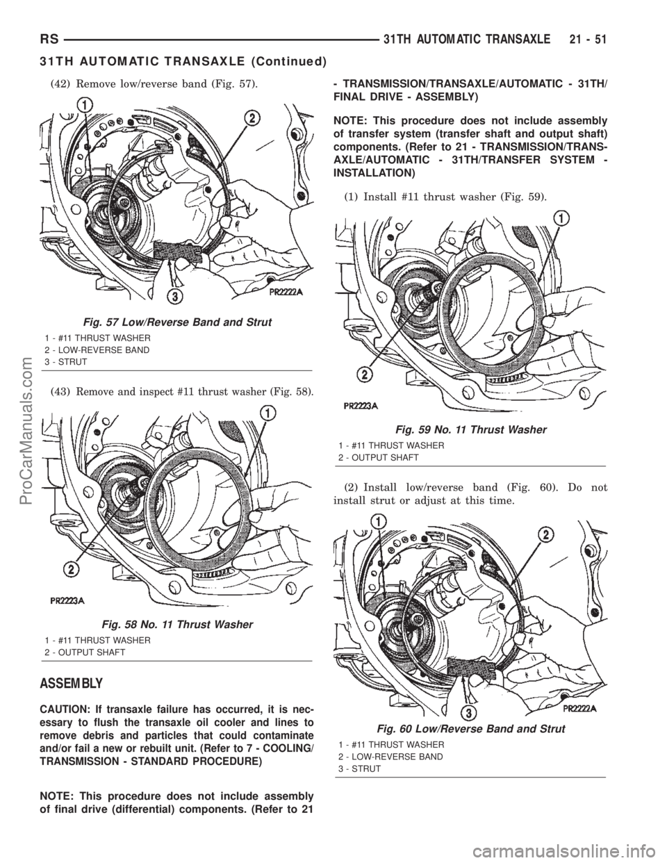
(42) Remove low/reverse band (Fig. 57).
(43)
Remove and inspect #11 thrust washer (Fig. 58).
ASSEMBLY
CAUTION: If transaxle failure has occurred, it is nec-
essary to flush the transaxle oil cooler and lines to
remove debris and particles that could contaminate
and/or fail a new or rebuilt unit. (Refer to 7 - COOLING/
TRANSMISSION - STANDARD PROCEDURE)
NOTE: This procedure does not include assembly
of final drive (differential) components. (Refer to 21- TRANSMISSION/TRANSAXLE/AUTOMATIC - 31TH/
FINAL DRIVE - ASSEMBLY)
NOTE: This procedure does not include assembly
of transfer system (transfer shaft and output shaft)
components. (Refer to 21 - TRANSMISSION/TRANS-
AXLE/AUTOMATIC - 31TH/TRANSFER SYSTEM -
INSTALLATION)
(1) Install #11 thrust washer (Fig. 59).
(2) Install low/reverse band (Fig. 60). Do not
install strut or adjust at this time.
Fig. 57 Low/Reverse Band and Strut
1 - #11 THRUST WASHER
2 - LOW-REVERSE BAND
3 - STRUT
Fig. 58 No. 11 Thrust Washer
1 - #11 THRUST WASHER
2 - OUTPUT SHAFT
Fig. 59 No. 11 Thrust Washer
1 - #11 THRUST WASHER
2 - OUTPUT SHAFT
Fig. 60 Low/Reverse Band and Strut
1 - #11 THRUST WASHER
2 - LOW-REVERSE BAND
3 - STRUT
RS31TH AUTOMATIC TRANSAXLE21-51
31TH AUTOMATIC TRANSAXLE (Continued)
ProCarManuals.com
Page 1611 of 2399
(13) Install rear clutch assembly (Fig. 69). Ensure
that all clutch discs are engaged to front planetary
gear splines or transaxle failure will result.
(14) Install #2 thrust washer (Fig. 69).
(15) Install front clutch assembly (Fig. 70). Ensure
that all clutch discs are engaged to rear clutch
retainer splines or transaxle failure will result.(16) Install kickdown band (Fig. 71). Do not install
strut or adjust at this time.
(17) Install oil pump gasket (Fig. 72).
Fig. 69 No. 2 Thrust Washer and Rear Clutch
1 - REAR CLUTCH ASSEMBLY
2 - #2 THRUST WASHER
Fig. 70 Front Clutch Assembly
1 - REAR CLUTCH ASSEMBLY
2 - FRONT CLUTCH ASSEMBLY
Fig. 71 Kickdown Band and Strut
1 - FRONT CLUTCH
2 - KICKDOWN BAND
3 - OIL RETURN AND FEED HOLE TO DIFFERENTIAL
4 - STRUT
Fig. 72 Oil Pump Gasket
1 - SPLIT IN GASKET (DIFFERENTIAL OIL FEED)
2 - PUMP GASKET
3 - PUMP GASKET DIFFERENTIAL OIL FEED CUTOUT
21 - 54 31TH AUTOMATIC TRANSAXLERS
31TH AUTOMATIC TRANSAXLE (Continued)
ProCarManuals.com
Page 1612 of 2399
(18) Inspect #1 thrust washer (on reaction support)
and replace as necessary.
(19) Install oil pump to transaxle (Fig. 73). Torque
bolts to 31 N´m (275 in. lbs.).
(20) Set up tools as shown in (Fig. 74) to measure
input shaft end play.Input shaft end play should
be within 0.19-1.50mm (0.008-0.060 in.).(21) Install park pawl, spring, and pivot shaft (Fig.
75)
(22) Install rod support and bolts (Fig. 76). Torque
bolts to 28 N´m (250 in. lbs.). (Fig. 77).
Fig. 73 Oil Pump Attaching Bolts
1 - SEAL
2 - PUMP ATTACHING BOLTS (7)
3 - PUMP HOUSING
Fig. 74 Measure Input Shaft End Play using End
Play Set 8266
1 - TOOL 8266±8
2 - TOOL 8266±2
3 - TOOL C-3339
Fig. 75 Parking Pawl, Return Spring, and Pivot Shaft
1 - PARK PAWL
2 - RETURN SPRING
3 - NOTE: SMALL DIAMETER TO REAR
4 - PIVOT SHAFT
Fig. 76 Support and Bolts
1 - BOLT (2)
2 - PARKING SPRAG ROD SUPPORT
RS31TH AUTOMATIC TRANSAXLE21-55
31TH AUTOMATIC TRANSAXLE (Continued)
ProCarManuals.com
Page 1617 of 2399
(40) Install oil filter and gasket into position (Fig.
93).
(41) Install oil filter-to-valve body screws (Fig. 94)
and torque to 5 N´m (45 in. lbs.) torque.(42) Install an 1/8º bead of MopartSilicone Rub-
ber Adhesive Sealant to the transaxle oil pan (Fig.
95). Install oil pan to case and immediately install
and torque oil pan-to-case bolts (Fig. 96) to 19 N´m
(165 in. lbs.) torque.
Fig. 93 Oil Filter and Gasket
1 - OIL FILTER
2 - GASKET
3 - VALVE BODY
Fig. 94 Oil Filter Screws
1 - SCREWDRIVER HANDLE
2 - SPECIAL TOOL L-4553
3 - OIL FILTER SCREWS (2)
4 - OIL FILTER
Fig. 95 Transaxle Oil Pan
1 - TRANSAXLE OIL PAN
2 - OIL FILTER
Fig. 96 Transaxle Oil Pan Bolts
1 - TRANSAXLE OIL PAN
2 - OIL PAN BOLTS
21 - 60 31TH AUTOMATIC TRANSAXLERS
31TH AUTOMATIC TRANSAXLE (Continued)
ProCarManuals.com
Page 1619 of 2399
(9) Install structural collar (Fig. 99).
(10) Connect transaxle cooler lines using service
splice kit. Refer to instructions included with kit.
(11) Install starter motor assembly (Fig. 100).(12) Install front mount and bracket (Fig. 101).
Fig. 99 Structural Collar
1 - BOLT - COLLAR TO OIL PAN
2 - BOLT - COLLAR TO TRANSAXLE
3 - STRUCTURAL COLLAR
4 - OIL PAN
Fig. 100 Starter Motor Removal/Installation
1 - STARTER MOTOR
2 - BOLT
3 - BOLT
Fig. 101 Front Mount and Bracket
1 - BRACKET - FRONT MOUNT
2 - NUT
3 - BOLT
4 - MOUNT - FRONT INSULATOR
5 - BOLT
6 - BOLT
7 - FRONT CROSSMEMBER
21 - 62 31TH AUTOMATIC TRANSAXLERS
31TH AUTOMATIC TRANSAXLE (Continued)
ProCarManuals.com
Page 1629 of 2399

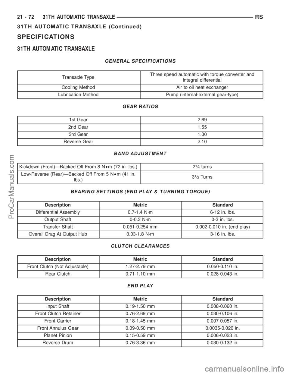
SPECIFICATIONS
31TH AUTOMATIC TRANSAXLE
GENERAL SPECIFICATIONS
Transaxle TypeThree speed automatic with torque converter and
integral differential
Cooling Method Air to oil heat exchanger
Lubrication Method Pump (internal-external gear-type)
GEAR RATIOS
1st Gear 2.69
2nd Gear 1.55
3rd Gear 1.00
Reverse Gear 2.10
BAND ADJUSTMENT
Kickdown (Front)ÐBacked Off From 8 N²m (72 in. lbs.) 21¤4turns
Low-Reverse (Rear)ÐBacked Off From 5 N²m (41 in.
lbs.)3
1¤2Turns
BEARING SETTINGS (END PLAY & TURNING TORQUE)
Description Metric Standard
Differential Assembly 0.7-1.4 N´m 6-12 in. lbs.
Output Shaft 0-0.3 N´m 0-3 in. lbs.
Transfer Shaft 0.051-0.254 mm 0.002-0.010 in. (end play)
Overall Drag At Output Hub 0.03-1.8 N´m 3-16 in. lbs.
CLUTCH CLEARANCES
Description Metric Standard
Front Clutch (Not Adjustable) 1.27-2.79 mm 0.050-0.110 in.
Rear Clutch 0.71-1.10 mm 0.028-0.043 in.
END PLAY
Description Metric Standard
Input Shaft 0.19-1.50 mm 0.008-0.060 in.
Front Clutch Retainer 0.76-2.69 mm 0.030-0.106 in.
Front Carrier 0.18-1.45 mm 0.007-0.057 in.
Front Annulus Gear 0.09-0.50 mm 0.0035-0.020 in.
Planet Pinion 0.15-0.59 mm 0.006-0.023 in.
Reverse Drum 0.76-3.36 mm 0.030-0.132 in.
21 - 72 31TH AUTOMATIC TRANSAXLERS
31TH AUTOMATIC TRANSAXLE (Continued)
ProCarManuals.com