2002 CHRYSLER CARAVAN glove box
[x] Cancel search: glove boxPage 1152 of 2399
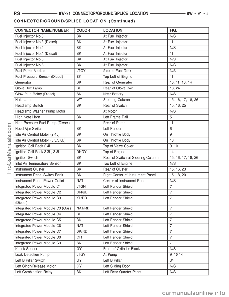
CONNECTOR NAME/NUMBER COLOR LOCATION FIG.
Fuel Injector No.3 BK At Fuel Injector N/S
Fuel Injector No.3 (Diesel) BK At Fuel Injector 11
Fuel Injector No.4 BK At Fuel Injector N/S
Fuel Injector No.4 (Diesel) BK At Fuel Injector 11
Fuel Injector No.5 BK At Fuel Injector N/S
Fuel Injector No.6 BK At Fuel Injector N/S
Fuel Pump Module LTGY Side of Fuel Tank N/S
Fuel Pressure Sensor (Diesel) BK Top Left of Engine 11
Generator BK Rear of Generator 10, 11, 13, 14
Glove Box Lamp BL Rear of Glove Box 18, 24
Glow Plug Relay (Diesel) BK Near Battery N/S
Halo Lamp WT Steering Column 15, 16, 17, 18, 26
Headlamp Switch BK Rear of Switch 15, 16, 25
Headlamp Washer Pump Motor At Motor N/S
High Note Horn BK Left Frame Rail 5
High Pressure Fuel Pump (Diesel) Rear of Pump 11
Hood Ajar Switch BK Left Fender 6
Idle Air Control Motor (2.4L) BK On Throttle Body 9
Idle Air Control Motor (3.3/3.8L) BK On Throttle Body 13
Ignition Coil Pack 2.4L BK Top of Valve Cover 9, 10
Ignition Coil Pack 3.3L, 3.8L DKGY Top of Engine 14
Ignition Switch BK Rear of Switch at Steering Column 15, 16, 17, 18, 26
Inlet Air Temperature Sensor BK Top Left of Engine N/S
Instrument Cluster BK Rear of Cluster 15, 16, 23
Instrument Panel Switch Bank BK Right Center of Instrument Panel 15, 18, 20
Instrument Panel Power Outlet NAT Center of Instrument Panel N/S
Integrated Power Module C1 LTGN Left Fender Shield 7
Integrated Power Module C2 GN/BL Left Fender Shield 7
Integrated Power Module C3
(Diesel)YL/RD Left Fender Shield 7
Integrated Power Module C3 (Gas) NAT/RD Left Fender Shield 7
Integrated Power Module C4 BL Left Fender Shield 7
Integrated Power Module C5 BK Left Fender Shield 7
Integrated Power Module C6 NAT Left Fender Shield 7
Integrated Power Module C7 BK/RD Left Fender Shield 7
Integrated Power Module C8 OR Left Fender Shield 7
Integrated Power Module C9 BK Left Fender Shield 7
Knock Sensor GY Front of Cylinder Block N/S
Leak Detection Pump LTGY At Pump 9, 10 14
Left B Pillar Switch GY Left B Pillar 34
Left Cinch/Release Motor GY Left Sliding Door N/S
Left Combination Relay BK Left Rear Quarter Panel N/S
RS8W-91 CONNECTOR/GROUND/SPLICE LOCATION8W-91-5
CONNECTOR/GROUND/SPLICE LOCATION (Continued)
ProCarManuals.com
Page 1196 of 2399
8W-97 POWER DISTRIBUTION SYSTEM
TABLE OF CONTENTS
page page
POWER DISTRIBUTION SYSTEM
DESCRIPTION..........................1
OPERATION............................1
SPECIAL TOOLS
POWER DISTRIBUTION SYSTEMS.........2
ACCESSORY RELAY
DESCRIPTION..........................2
OPERATION............................2
DIAGNOSIS AND TESTING
DIAGNOSIS & TESTING - ACCESSORY
RELAY...............................2
REMOVAL.............................3
INSTALLATION..........................3
INTEGRATED POWER MODULE
DESCRIPTION..........................3OPERATION............................3
REMOVAL.............................4
INSTALLATION..........................4
IOD FUSE
DESCRIPTION..........................4
OPERATION............................5
REMOVAL.............................5
INSTALLATION..........................5
POWER OUTLET
DESCRIPTION..........................5
OPERATION............................5
DIAGNOSIS AND TESTING
DIAGNOSIS & TESTING - POWER OUTLET . . 5
REMOVAL.............................6
INSTALLATION..........................6
POWER DISTRIBUTION
SYSTEM
DESCRIPTION
This group covers the various standard and
optional power distribution components used on this
model. The power distribution system for this vehicle
consists of the following components:
²Integrated Power Module (IPM)
²Front Control Module (FCM)
²Power Outlets
Refer to Wiring Diagrams for complete circuit sche-
matics.
The power distribution system also incorporates
various types of circuit control and protection fea-
tures, including:
²Automatic resetting circuit breakers
²Blade-type fuses
²Bus bars
²Cartridge fuses
²Circuit splice blocks
²Flashers
²Fusible links
²Relays
Following are general descriptions of the major
components in the power distribution system. See the
owner's manual in the vehicle glove box for more
information on the features and use of all of the
power distribution system components.
OPERATION
The power distribution system for this vehicle is
designed to provide safe, reliable, and centralized dis-
tribution points for the electrical current required to
operate all of the many standard and optional facto-
ry-installed electrical and electronic powertrain,
chassis, safety, security, comfort and convenience sys-
tems. At the same time, the power distribution sys-
tem was designed to provide ready access to these
electrical distribution points for the vehicle techni-
cian to use when conducting diagnosis and repair of
faulty circuits. The power distribution system can
also prove useful for the sourcing of additional elec-
trical circuits that may be required to provide the
electrical current needed to operate many accessories
that the vehicle owner may choose to have installed
in the aftermarket.
RS8W-97 POWER DISTRIBUTION SYSTEM8W-97-1
ProCarManuals.com
Page 2046 of 2399
INSTRUMENT PANEL
TABLE OF CONTENTS
page page
CLUSTER BEZEL
REMOVAL.............................63
INSTALLATION.........................63
CUP HOLDER
REMOVAL.............................64
INSTALLATION.........................64
GLOVE BOX
REMOVAL.............................64
INSTALLATION.........................64
GLOVE BOX LATCH
REMOVAL.............................64
INSTALLATION.........................64
GLOVE BOX LATCH STRIKER
REMOVAL.............................64
INSTALLATION.........................65
INSTRUMENT PANEL ASSEMBLY
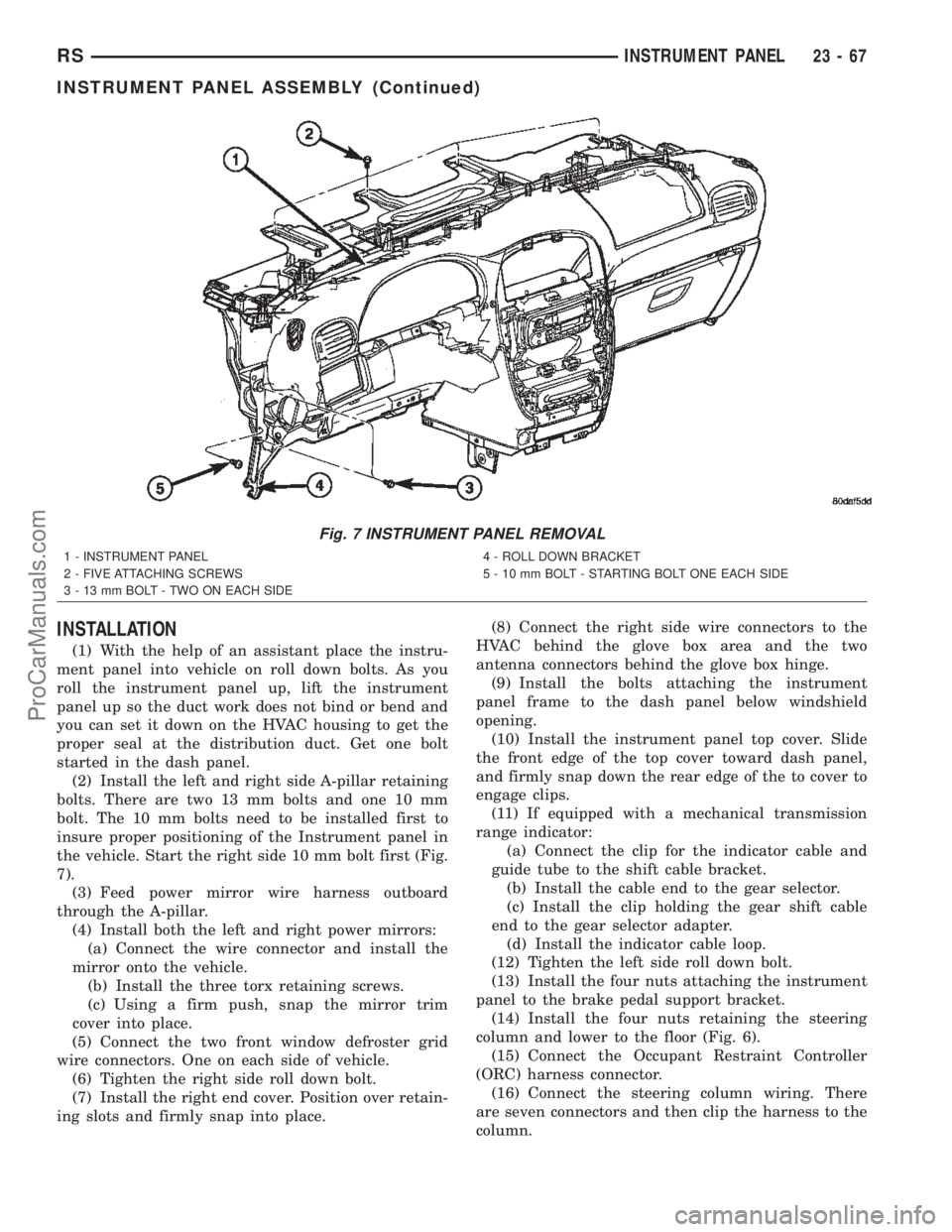
REMOVAL.............................65
INSTALLATION.........................67
INSTRUMENT PANEL CENTER BEZEL
REMOVAL.............................68
INSTALLATION.........................68INSTRUMENT PANEL END CAP
REMOVAL.............................68
INSTALLATION.........................68
INSTRUMENT PANEL TOP COVER
REMOVAL.............................69
INSTALLATION.........................69
LOWER CONSOLE
REMOVAL.............................69
INSTALLATION.........................69
LOWER INSTRUMENT PANEL
REMOVAL.............................70
INSTALLATION.........................70
LOWER STEERING COLUMN COVER
REMOVAL.............................70
INSTALLATION.........................70
STEERING COLUMN COVER BACKING PLATE
REMOVAL.............................70
INSTALLATION.........................71
OVER STEERING COLUMN COVER
REMOVAL.............................71
INSTALLATION.........................71
CLUSTER BEZEL
REMOVAL
(1) Disconnect and isolate the battery negative
cable.
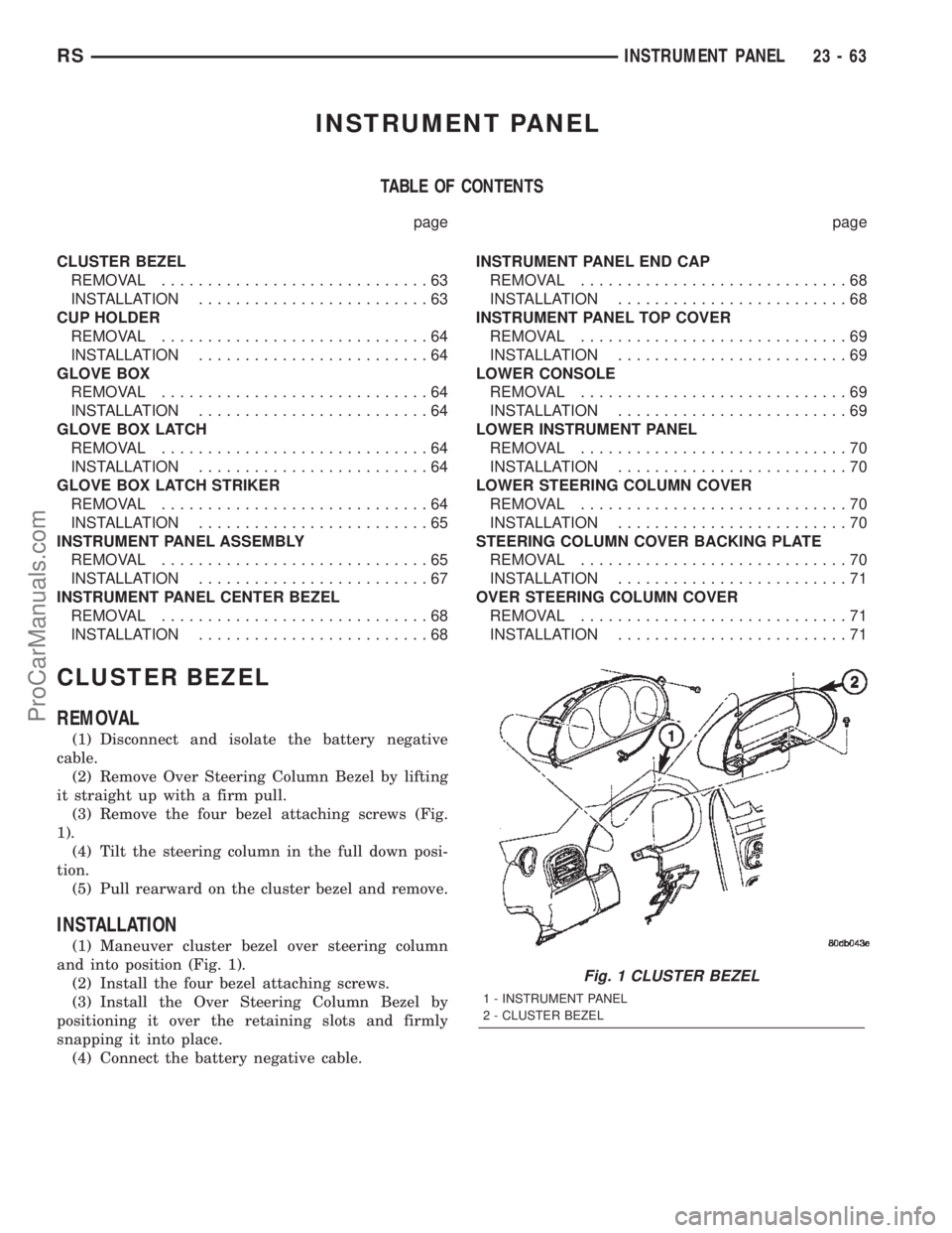
(2) Remove Over Steering Column Bezel by lifting
it straight up with a firm pull.
(3) Remove the four bezel attaching screws (Fig.
1).
(4) Tilt the steering column in the full down posi-
tion.
(5) Pull rearward on the cluster bezel and remove.
INSTALLATION
(1) Maneuver cluster bezel over steering column
and into position (Fig. 1).
(2) Install the four bezel attaching screws.
(3) Install the Over Steering Column Bezel by
positioning it over the retaining slots and firmly
snapping it into place.
(4) Connect the battery negative cable.
Fig. 1 CLUSTER BEZEL
1 - INSTRUMENT PANEL
2 - CLUSTER BEZEL
RSINSTRUMENT PANEL23-63
ProCarManuals.com
Page 2047 of 2399
CUP HOLDER
REMOVAL
(1) Remove the screw access cover from the bottom
of the center bezel.
(2) Remove the center bezel attaching screws.
(3) Using a trim stick (special tool #C-4755) or
equivalent, gently pry out on the edge of the instru-
ment panel center bezel. Hang off to the side leaving
the accessory switches connected.
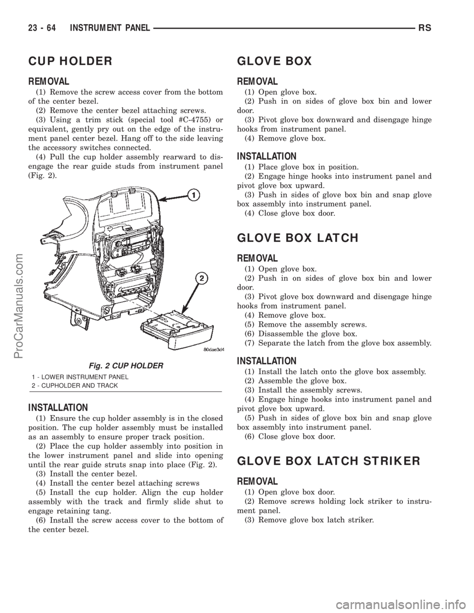
(4) Pull the cup holder assembly rearward to dis-
engage the rear guide studs from instrument panel
(Fig. 2).
INSTALLATION
(1) Ensure the cup holder assembly is in the closed
position. The cup holder assembly must be installed
as an assembly to ensure proper track position.
(2) Place the cup holder assembly into position in
the lower instrument panel and slide into opening
until the rear guide struts snap into place (Fig. 2).
(3) Install the center bezel.
(4) Install the center bezel attaching screws
(5) Install the cup holder. Align the cup holder
assembly with the track and firmly slide shut to
engage retaining tang.
(6) Install the screw access cover to the bottom of
the center bezel.
GLOVE BOX
REMOVAL
(1) Open glove box.
(2) Push in on sides of glove box bin and lower
door.
(3) Pivot glove box downward and disengage hinge
hooks from instrument panel.
(4) Remove glove box.
INSTALLATION
(1) Place glove box in position.
(2) Engage hinge hooks into instrument panel and
pivot glove box upward.
(3) Push in sides of glove box bin and snap glove
box assembly into instrument panel.
(4) Close glove box door.
GLOVE BOX LATCH
REMOVAL
(1) Open glove box.
(2) Push in on sides of glove box bin and lower
door.
(3) Pivot glove box downward and disengage hinge
hooks from instrument panel.
(4) Remove glove box.
(5) Remove the assembly screws.
(6) Disassemble the glove box.
(7) Separate the latch from the glove box assembly.
INSTALLATION
(1) Install the latch onto the glove box assembly.
(2) Assemble the glove box.
(3) Install the assembly screws.
(4) Engage hinge hooks into instrument panel and
pivot glove box upward.
(5) Push in sides of glove box bin and snap glove
box assembly into instrument panel.
(6) Close glove box door.
GLOVE BOX LATCH STRIKER
REMOVAL
(1) Open glove box door.
(2) Remove screws holding lock striker to instru-
ment panel.
(3) Remove glove box latch striker.
Fig. 2 CUP HOLDER
1 - LOWER INSTRUMENT PANEL
2 - CUPHOLDER AND TRACK
23 - 64 INSTRUMENT PANELRS
ProCarManuals.com
Page 2048 of 2399
INSTALLATION
(1) Install the glove box latch striker.
(2) Install the screws holding latch striker to
instrument panel.
(3) Close glove box door.
INSTRUMENT PANEL
ASSEMBLY
REMOVAL
(1) Disconnect and isolate the battery negative
cable.
(2) Remove the lower console:
(a) Remove six retaining screws.
(b) Pull rearward and disconnect the auxiliary
power outlet.
(c) Remove lower console from vehicle.
(3) Remove the bolts attaching the lower supports
to the instrument panel frame (Fig. 3).
(4) Remove the bolts attaching the lower supports
to the floor pan.
(5) Disconnect the wire connectors from the Pas-
senger Airbag.
(6) Remove the two screws to each right and left
cowl trim covers.
(7) Remove the both left and right side A-pillar
trim covers using a trim stick (special tool #C-4755)
or equivalent gently pry out on the trim covers and
remove.
(8) Remove the glove box:
(a) Push in on sides of glove box bin and lower
door.
(b) Pivot glove box downward and disengage
hinge hooks from instrument panel.
(c) Remove glove box from vehicle.
(9) Disconnect the antenna lead connector from
behind the glove box.
(10) Remove the four screws to the lower steering
column cover.
(11) Remove the eight screws to the steering col-
umn backing plate.
(12) Unclip the Data Link Connector (DLC) from
the steering column backing plate.
(13) Remove two screws to the left side instrument
panel silencer and remove (Fig. 4).
(14) Disconnect the left side wiring:
(a) Brake switch.
(b) Main bulkhead connector.
(c) Five harness connectors.
(d) Driver airbag connector.
(15) Remove the two screws to the hood release
handle.
(16) Remove five screws to steering column back-
ing plate and remove (Refer to 23 - BODY/INSTRU-
MENT PANEL/KNEE BLOCKER - REMOVAL).(17) Remove the two steering column shroud
retaining screws. Separate the shrouds and remove
from vehicle.
(18) Remove the screws attaching the instrument
panel reinforcement and remove (Fig. 5).
(19) Disconnect the steering column wiring. There
are seven connectors and then unclip the harness
from the column.
(20) Disconnect the Occupant Restraint Controller
(ORC) harness connector.
(21) Remove the four nuts retaining the steering
column to the dash panel steering column mounting
bracket and lower column to the floor (Fig. 6).
(22) Remove the four nuts attaching the instru-
ment panel to the brake pedal support bracket.
(23) Loosen the left side roll down bolt (Fig. 7).
(24) Remove the left side A-pillar retaining bolts.
There are two 13 mm bolts and one 10 mm bolt.
(25) If equipped with a mechanical transmission
range indicator:
(a) Remove the indicator cable loop.
(b) Remove the clip holding gear shift cable end
to the gear selector adapter.
(c) Pull the cable end from gear selector.
(d) Disconnect the clip for the indicator cable
and guide tube from the shift cable bracket and
move out of the way.
(26) Remove the instrument panel top cover. Using
a trim stick or equivalent, gently pry up on the front
edge of the top cover, pull rearward and remove from
vehicle.
(27) Disconnect the right side wire connectors from
the HVAC behind the glove box area and the two
antenna connectors behind the glove box hinge.
(28) Remove the right end cover by pulling out-
board.
(29) Remove the right side A-pillar retaining bolts.
There are two 13 mm bolts and one 10 mm bolt.
(30) Loosen the right side roll down bolt.
(31) Disconnect the two front window defroster
grid wire connectors. One on each side of vehicle.
(32) Remove both the left and right power mirrors:
(a) Using a trim stick or equivalent, gently pry
out on mirror trim cover.
(b) Open door and remove the three torx retain-
ing screws.
(c) Disconnect the wire connector and remove
mirror from the vehicle.
(33) Feed power mirror wire harness inboard
through the A-pillar.
(34) Remove the bolts attaching the instrument
panel frame to the dash panel below windshield
opening.
(35) With the help of an assistant remove the
instrument panel from vehicle. Lift the instrument
RSINSTRUMENT PANEL23-65
GLOVE BOX LATCH STRIKER (Continued)
ProCarManuals.com
Page 2050 of 2399
INSTALLATION
(1) With the help of an assistant place the instru-
ment panel into vehicle on roll down bolts. As you
roll the instrument panel up, lift the instrument
panel up so the duct work does not bind or bend and
you can set it down on the HVAC housing to get the
proper seal at the distribution duct. Get one bolt
started in the dash panel.
(2) Install the left and right side A-pillar retaining
bolts. There are two 13 mm bolts and one 10 mm
bolt. The 10 mm bolts need to be installed first to
insure proper positioning of the Instrument panel in
the vehicle. Start the right side 10 mm bolt first (Fig.
7).
(3) Feed power mirror wire harness outboard
through the A-pillar.
(4) Install both the left and right power mirrors:
(a) Connect the wire connector and install the
mirror onto the vehicle.
(b) Install the three torx retaining screws.
(c) Using a firm push, snap the mirror trim
cover into place.
(5) Connect the two front window defroster grid
wire connectors. One on each side of vehicle.
(6) Tighten the right side roll down bolt.
(7) Install the right end cover. Position over retain-
ing slots and firmly snap into place.(8) Connect the right side wire connectors to the
HVAC behind the glove box area and the two
antenna connectors behind the glove box hinge.
(9) Install the bolts attaching the instrument
panel frame to the dash panel below windshield
opening.
(10) Install the instrument panel top cover. Slide
the front edge of the top cover toward dash panel,
and firmly snap down the rear edge of the to cover to
engage clips.
(11) If equipped with a mechanical transmission
range indicator:
(a) Connect the clip for the indicator cable and
guide tube to the shift cable bracket.
(b) Install the cable end to the gear selector.
(c) Install the clip holding the gear shift cable
end to the gear selector adapter.
(d) Install the indicator cable loop.
(12) Tighten the left side roll down bolt.
(13) Install the four nuts attaching the instrument
panel to the brake pedal support bracket.
(14) Install the four nuts retaining the steering
column and lower to the floor (Fig. 6).
(15) Connect the Occupant Restraint Controller
(ORC) harness connector.
(16) Connect the steering column wiring. There
are seven connectors and then clip the harness to the
column.
Fig. 7 INSTRUMENT PANEL REMOVAL
1 - INSTRUMENT PANEL
2 - FIVE ATTACHING SCREWS
3 - 13 mm BOLT - TWO ON EACH SIDE4 - ROLL DOWN BRACKET
5 - 10 mm BOLT - STARTING BOLT ONE EACH SIDE
RSINSTRUMENT PANEL23-67
INSTRUMENT PANEL ASSEMBLY (Continued)
ProCarManuals.com
Page 2051 of 2399
(17) Install the screws attaching the instrument
panel reinforcement (Fig. 5).
(18) Connect the shrouds and install the two steer-
ing column shroud retaining screws.
(19) Install five screws to the left under column
instrument panel reinforcement brace.
(20) Install the two screws to the hood release
handle.
(21) Connect the left side wiring:
(a) Brake switch.
(b) Main bulkhead connector.
(c) Five harness connectors.
(d) Driver airbag connector.
(22) Install two screws to the left side instrument
panel silencer (Fig. 4).
(23) Clip the Data Link Connector (DLC) to the
steering column backing plate.
(24) Install the eight screws to the steering column
backing plate.
(25) Install the four screws to the lower steering
column cover.
(26) Install the glove box:
(a) Install glove box into the vehicle. Line up the
hinges and firmly snap together.
(b) Push in on sides of glove box bin and raise
door.
(27) Install the both left and right side A-pillar
trim covers. Position trim cover over slots and firmly
snap into place.
(28) Install the two screws to each right and left
cowl trim covers.
(29) Connect the wire connectors to the Passenger
Airbag.
(30) Install the bolts attaching the lower supports
to the floor pan.
(31) Install the bolts attaching the lower supports
to the instrument panel frame (Fig. 3).
(32) Install the lower console:
(a) Install lower console to vehicle.
(b) Connect the auxiliary power outlet.
(c) Install the six retaining screws.
(33) Connect the battery negative cable.
INSTRUMENT PANEL CENTER
BEZEL
REMOVAL
(1) Disconnect and isolate the battery negative
cable.
(2) Insert the trim stick (special tool #C-4755) or
equivalent between access cover and center bezel
gently pry outward.
(3) Carefully pry the access cover from the instru-
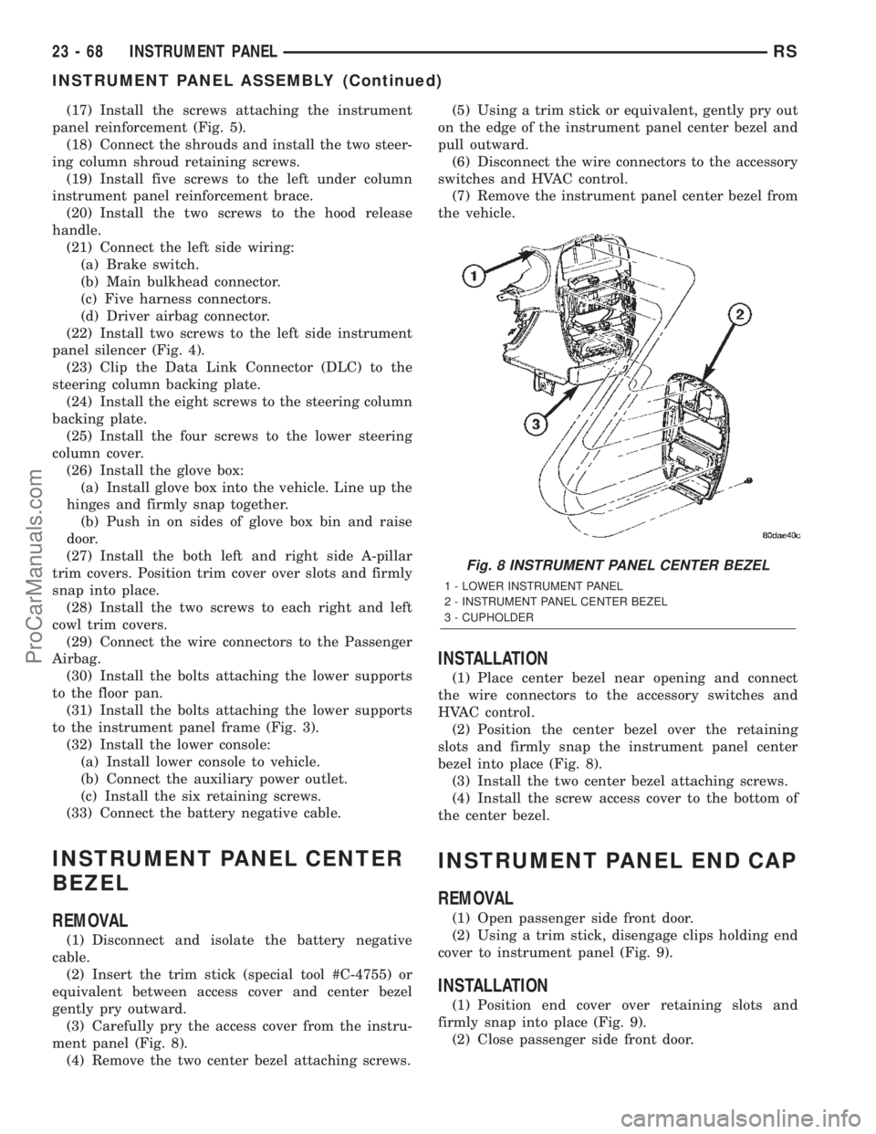
ment panel (Fig. 8).
(4) Remove the two center bezel attaching screws.(5) Using a trim stick or equivalent, gently pry out
on the edge of the instrument panel center bezel and
pull outward.
(6) Disconnect the wire connectors to the accessory
switches and HVAC control.
(7) Remove the instrument panel center bezel from
the vehicle.
INSTALLATION
(1) Place center bezel near opening and connect
the wire connectors to the accessory switches and
HVAC control.
(2) Position the center bezel over the retaining
slots and firmly snap the instrument panel center
bezel into place (Fig. 8).
(3) Install the two center bezel attaching screws.
(4) Install the screw access cover to the bottom of
the center bezel.
INSTRUMENT PANEL END CAP
REMOVAL
(1) Open passenger side front door.
(2) Using a trim stick, disengage clips holding end
cover to instrument panel (Fig. 9).
INSTALLATION
(1) Position end cover over retaining slots and
firmly snap into place (Fig. 9).
(2) Close passenger side front door.
Fig. 8 INSTRUMENT PANEL CENTER BEZEL
1 - LOWER INSTRUMENT PANEL
2 - INSTRUMENT PANEL CENTER BEZEL
3 - CUPHOLDER
23 - 68 INSTRUMENT PANELRS
INSTRUMENT PANEL ASSEMBLY (Continued)
ProCarManuals.com
Page 2053 of 2399
LOWER INSTRUMENT PANEL
REMOVAL
When servicing the lower instrument panel, refer
to Body, Instrument Panel, and then the appropriate
removal procedure.
(1) Remove the right end cover.
(2) Remove the lower steering column cover.
(3) Remove the center bezel.
(4) Remove the lower console.
(5) Remove the cup holder and track.
(6) Remove the glove box.
(7) Remove the glove box latch striker.
(8) Remove the glove box lamp.
(9) Remove the eighteen screws holding the lower
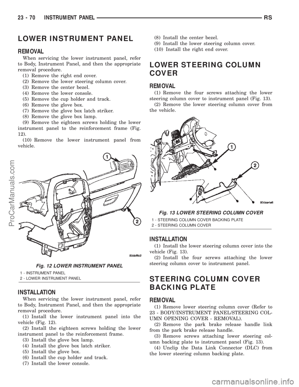
instrument panel to the reinforcement frame (Fig.
12).
(10) Remove the lower instrument panel from
vehicle.
INSTALLATION
When servicing the lower instrument panel, refer
to Body, Instrument Panel, and then the appropriate
removal procedure.
(1) Install the lower instrument panel into the
vehicle (Fig. 12).
(2) Install the eighteen screws holding the lower
instrument panel to the reinforcement frame.
(3) Install the glove box lamp.
(4) Install the glove box latch striker.
(5) Install the glove box.
(6) Install the cup holder and track.
(7) Install the lower console.(8) Install the center bezel.
(9) Install the lower steering column cover.
(10) Install the right end cover.
LOWER STEERING COLUMN
COVER
REMOVAL
(1) Remove the four screws attaching the lower
steering column cover to instrument panel (Fig. 13).
(2) Remove the lower steering column cover from
the vehicle.
INSTALLATION
(1) Install the lower steering column cover into the
vehicle (Fig. 13).
(2) Install the four screws attaching the lower
steering column cover to instrument panel.
STEERING COLUMN COVER
BACKING PLATE
REMOVAL
(1) Remove lower steering column cover (Refer to
23 - BODY/INSTRUMENT PANEL/STEERING COL-
UMN OPENING COVER - REMOVAL).
(2) Remove the park brake release handle link
from the park brake release handle.
(3) Remove screws attaching lower steering col-
umn backing plate to instrument panel (Fig. 13).
(4) Unclip the Data Link Connector (DLC) from
the lower steering column backing plate.
Fig. 12 LOWER INSTRUMENT PANEL
1 - INSTRUMENT PANEL
2 - LOWER INSTRUMENT PANEL
Fig. 13 LOWER STEERING COLUMN COVER
1 - STEERING COLUMN COVER BACKING PLATE
2 - STEERING COLUMN COVER
23 - 70 INSTRUMENT PANELRS
ProCarManuals.com