2002 CHRYSLER CARAVAN service
[x] Cancel search: servicePage 1516 of 2399

(15) Disconnect the shift cable at the lever. (Fig. 4)
(16) Remove the pinch side clip, then remove the
cable from the bracket on the column.
(17) Remove the pinch bolt coupling. (Fig. 5)
(18) Loosen the two lower mounting nuts.
(19) Remove the two upper mounting nuts
(20) Remove the steering column.
(21) Remove the clockspring (Refer to 8 - ELEC-
TRICAL/RESTRAINTS/CLOCKSPRING - REMOV-
AL). (Fig. 6)
(22) Remove the mounting plate with the multi-
function switch.
(23) Remove the halo-lamp.(24) Remove the ignition key cylinder (Refer to 19
- STEERING/COLUMN/KEY/LOCK CYLINDER -
REMOVAL).
(25) Remove the BTSI.
INSTALLATION
To service the steering wheel components or the
airbag (Refer to 8 - ELECTRICAL/RESTRAINTS/
DRIVER AIRBAG - REMOVAL). Follow all WARN-
INGS AND CAUTIONS.
(1) Make sure the front wheels of the vehicle are
still in the STRAIGHT AHEAD position before begin-
ning the column installation procedure.
(2) Install the BTSI.
(3) Install the ignition key cylinder (Refer to 19 -
STEERING/COLUMN/KEY/LOCK CYLINDER -
INSTALLATION).
(4) Install the halo-lamp.
Fig. 3 STEERING WHEEL REMOVAL
1 - STEERING WHEEL
2 - PULLER
Fig. 4 SHIFT CABLE MOUNTING
1 - SHIFT CABLE MOUNT
2 - SHIFT LEVER
Fig. 5 PINCH BOLT
1 - PINCH BOLT
2 - STEERING COLUMN
Fig. 6 CLOCKSPRING
RSCOLUMN19-13
COLUMN (Continued)
ProCarManuals.com
Page 1544 of 2399
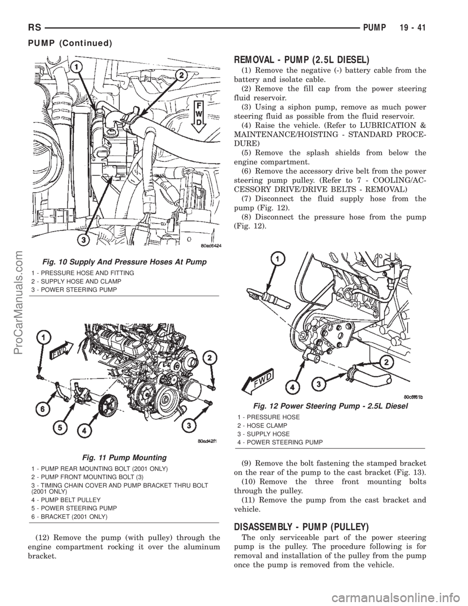
(12) Remove the pump (with pulley) through the
engine compartment rocking it over the aluminum
bracket.
REMOVAL - PUMP (2.5L DIESEL)
(1) Remove the negative (-) battery cable from the
battery and isolate cable.
(2) Remove the fill cap from the power steering
fluid reservoir.
(3) Using a siphon pump, remove as much power
steering fluid as possible from the fluid reservoir.
(4) Raise the vehicle. (Refer to LUBRICATION &
MAINTENANCE/HOISTING - STANDARD PROCE-
DURE)
(5) Remove the splash shields from below the
engine compartment.
(6) Remove the accessory drive belt from the power
steering pump pulley. (Refer to 7 - COOLING/AC-
CESSORY DRIVE/DRIVE BELTS - REMOVAL)
(7) Disconnect the fluid supply hose from the
pump (Fig. 12).
(8) Disconnect the pressure hose from the pump
(Fig. 12).
(9) Remove the bolt fastening the stamped bracket
on the rear of the pump to the cast bracket (Fig. 13).
(10) Remove the three front mounting bolts
through the pulley.
(11) Remove the pump from the cast bracket and
vehicle.
DISASSEMBLY - PUMP (PULLEY)
The only serviceable part of the power steering
pump is the pulley. The procedure following is for
removal and installation of the pulley from the pump
once the pump is removed from the vehicle.
Fig. 10 Supply And Pressure Hoses At Pump
1 - PRESSURE HOSE AND FITTING
2 - SUPPLY HOSE AND CLAMP
3 - POWER STEERING PUMP
Fig. 11 Pump Mounting
1 - PUMP REAR MOUNTING BOLT (2001 ONLY)
2 - PUMP FRONT MOUNTING BOLT (3)
3 - TIMING CHAIN COVER AND PUMP BRACKET THRU BOLT
(2001 ONLY)
4 - PUMP BELT PULLEY
5 - POWER STEERING PUMP
6 - BRACKET (2001 ONLY)
Fig. 12 Power Steering Pump - 2.5L Diesel
1 - PRESSURE HOSE
2 - HOSE CLAMP
3 - SUPPLY HOSE
4 - POWER STEERING PUMP
RSPUMP19-41
PUMP (Continued)
ProCarManuals.com
Page 1545 of 2399
(1) Remove the power steering pump from the
vehicle. Refer to Removal And Installation in this
section of the service manual.
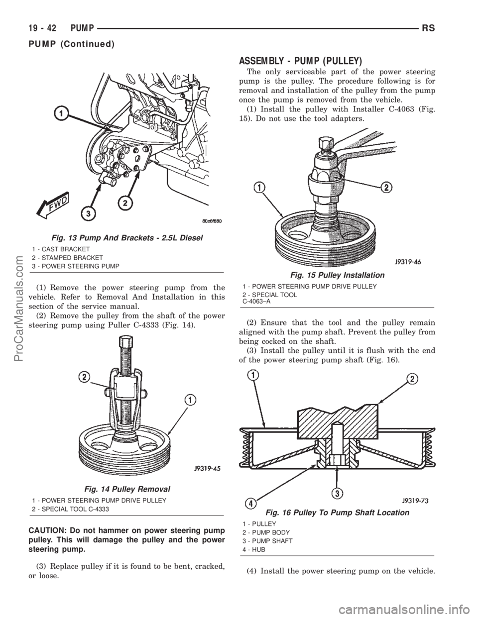
(2) Remove the pulley from the shaft of the power
steering pump using Puller C-4333 (Fig. 14).
CAUTION: Do not hammer on power steering pump
pulley. This will damage the pulley and the power
steering pump.
(3) Replace pulley if it is found to be bent, cracked,
or loose.
ASSEMBLY - PUMP (PULLEY)
The only serviceable part of the power steering
pump is the pulley. The procedure following is for
removal and installation of the pulley from the pump
once the pump is removed from the vehicle.
(1) Install the pulley with Installer C-4063 (Fig.
15). Do not use the tool adapters.
(2) Ensure that the tool and the pulley remain
aligned with the pump shaft. Prevent the pulley from
being cocked on the shaft.
(3) Install the pulley until it is flush with the end
of the power steering pump shaft (Fig. 16).
(4) Install the power steering pump on the vehicle.
Fig. 13 Pump And Brackets - 2.5L Diesel
1 - CAST BRACKET
2 - STAMPED BRACKET
3 - POWER STEERING PUMP
Fig. 14 Pulley Removal
1 - POWER STEERING PUMP DRIVE PULLEY
2 - SPECIAL TOOL C-4333
Fig. 15 Pulley Installation
1 - POWER STEERING PUMP DRIVE PULLEY
2 - SPECIAL TOOL
C-4063±A
Fig. 16 Pulley To Pump Shaft Location
1 - PULLEY
2 - PUMP BODY
3 - PUMP SHAFT
4 - HUB
19 - 42 PUMPRS
PUMP (Continued)
ProCarManuals.com
Page 1558 of 2399
TRANSMISSION/TRANSAXLE
TABLE OF CONTENTS
page page
POWER TRANSFER UNIT..................1
31TH AUTOMATIC TRANSAXLE.............2141TE AUTOMATIC TRANSAXLE............161
T850 MANUAL TRANSAXLE...............308
POWER TRANSFER UNIT
TABLE OF CONTENTS
page page
POWER TRANSFER UNIT
DESCRIPTION..........................1
OPERATION............................3
DIAGNOSIS AND TESTING
SEAL IDENTIFICATION..................3
FLUID LEAK DIAGNOSIS................4
STANDARD PROCEDURE
STANDARD PROCEDURE - FLUID LEVEL
INSPECTION..........................5
STANDARD PROCEDURE - PTU FLUID
CHANGE.............................5
REMOVAL.............................6
INSTALLATION..........................7
ADJUSTMENTS
OUTPUT FLANGE SHIM SELECTION.......7
SPECIFICATIONS
TORQUE.............................8
SPECIAL TOOLS
SDP POWER TRANSFER UNIT............8
DIFFERENTIAL CARRIER SEAL
REMOVAL.............................9
INSTALLATION..........................9
END COVER BALL BEARING
REMOVAL.............................9INSTALLATION.........................10
END COVER SEAL
REMOVAL.............................11
INSTALLATION.........................11
HALF SHAFT INNER SEAL
REMOVAL.............................12
INSTALLATION.........................13
INPUT SHAFT COVER SEAL
REMOVAL.............................13
INSTALLATION.........................14
INPUT SHAFT END SEAL
REMOVAL.............................16
INSTALLATION.........................16
INPUT SHAFT SEAL
REMOVAL.............................17
INSTALLATION.........................18
OUTER HALF SHAFT SEAL
REMOVAL.............................19
INSTALLATION.........................19
REAR COVER O-RING
REMOVAL.............................19
INSTALLATION.........................20
POWER TRANSFER UNIT
DESCRIPTION
The Power Transfer Unit (P.T.U.) is attached to a
modified automatic transaxle case where the right
half shaft extension housing would normally be
located.
The Power Transfer Unit is sealed from the trans-
axle and has its own oil sump. The Unit uses MopartSAE 80W-90 Gear and Axle Lubricant (MS-9020) and
holds 1.15 liters (1.22 quarts).
Service of the Power Transfer Unit is limited to:
²Fluid Change
²Seals
²Gaskets
²One ball bearing
²Output flange
If the ring gear and pinion, any tapered roller
bearings, case, covers, or pinion carrier fail the entire
unit must be replaced.
RSTRANSMISSION/TRANSAXLE21-1
ProCarManuals.com
Page 1561 of 2399
FLUID LEAK DIAGNOSIS
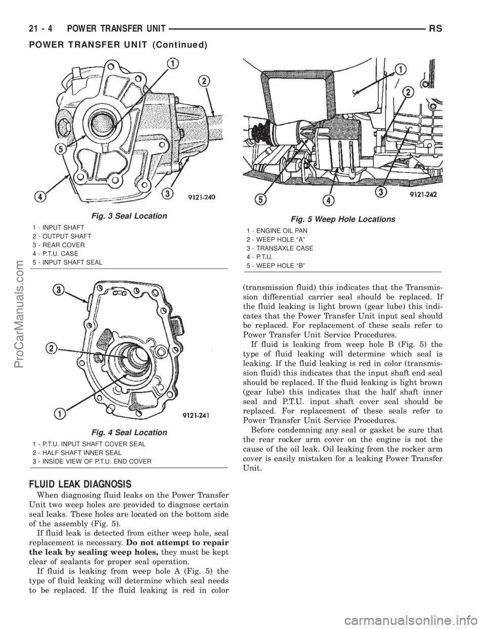
When diagnosing fluid leaks on the Power Transfer
Unit two weep holes are provided to diagnose certain
seal leaks. These holes are located on the bottom side
of the assembly (Fig. 5).
If fluid leak is detected from either weep hole, seal
replacement is necessary.Do not attempt to repair
the leak by sealing weep holes,they must be kept
clear of sealants for proper seal operation.
If fluid is leaking from weep hole A (Fig. 5) the
type of fluid leaking will determine which seal needs
to be replaced. If the fluid leaking is red in color(transmission fluid) this indicates that the Transmis-
sion differential carrier seal should be replaced. If
the fluid leaking is light brown (gear lube) this indi-
cates that the Power Transfer Unit input seal should
be replaced. For replacement of these seals refer to
Power Transfer Unit Service Procedures.
If fluid is leaking from weep hole B (Fig. 5) the
type of fluid leaking will determine which seal is
leaking. If the fluid leaking is red in color (transmis-
sion fluid) this indicates that the input shaft end seal
should be replaced. If the fluid leaking is light brown
(gear lube) this indicates that the half shaft inner
seal and P.T.U. input shaft cover seal should be
replaced. For replacement of these seals refer to
Power Transfer Unit Service Procedures.
Before condemning any seal or gasket be sure that
the rear rocker arm cover on the engine is not the
cause of the oil leak. Oil leaking from the rocker arm
cover is easily mistaken for a leaking Power Transfer
Unit.
Fig. 3 Seal Location
1 - INPUT SHAFT
2 - OUTPUT SHAFT
3 - REAR COVER
4 - P.T.U. CASE
5 - INPUT SHAFT SEAL
Fig. 4 Seal Location
1 - P.T.U. INPUT SHAFT COVER SEAL
2 - HALF SHAFT INNER SEAL
3 - INSIDE VIEW OF P.T.U. END COVER
Fig. 5 Weep Hole Locations
1 - ENGINE OIL PAN
2 - WEEP HOLE ªAº
3 - TRANSAXLE CASE
4 - P.T.U.
5 - WEEP HOLE ªBº
21 - 4 POWER TRANSFER UNITRS
POWER TRANSFER UNIT (Continued)
ProCarManuals.com
Page 1570 of 2399
INSTALLATION
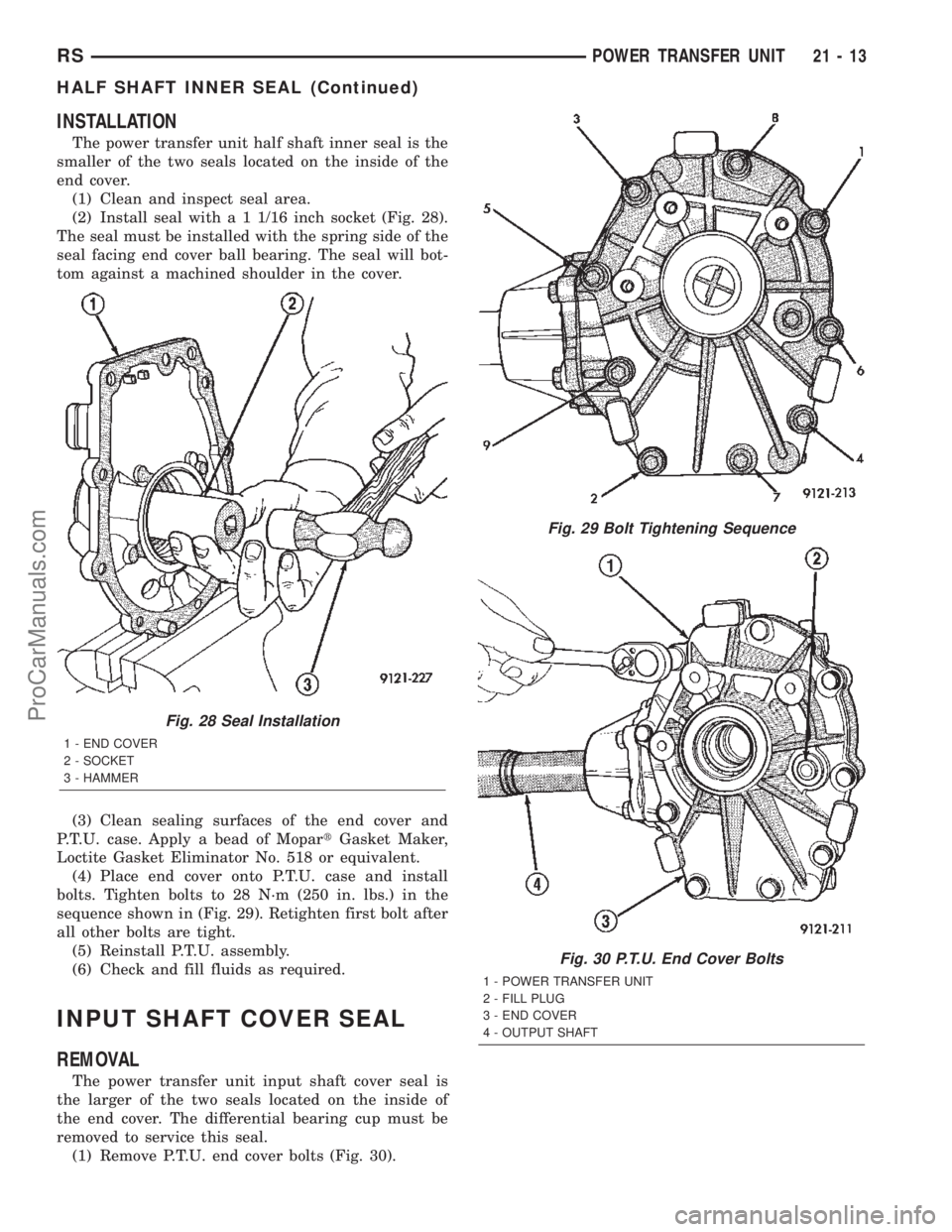
The power transfer unit half shaft inner seal is the
smaller of the two seals located on the inside of the
end cover.
(1) Clean and inspect seal area.
(2) Install seal with a 1 1/16 inch socket (Fig. 28).
The seal must be installed with the spring side of the
seal facing end cover ball bearing. The seal will bot-
tom against a machined shoulder in the cover.
(3) Clean sealing surfaces of the end cover and
P.T.U. case. Apply a bead of MopartGasket Maker,
Loctite Gasket Eliminator No. 518 or equivalent.
(4) Place end cover onto P.T.U. case and install
bolts. Tighten bolts to 28 N´m (250 in. lbs.) in the
sequence shown in (Fig. 29). Retighten first bolt after
all other bolts are tight.
(5) Reinstall P.T.U. assembly.
(6) Check and fill fluids as required.
INPUT SHAFT COVER SEAL
REMOVAL
The power transfer unit input shaft cover seal is
the larger of the two seals located on the inside of
the end cover. The differential bearing cup must be
removed to service this seal.
(1) Remove P.T.U. end cover bolts (Fig. 30).
Fig. 28 Seal Installation
1 - END COVER
2 - SOCKET
3 - HAMMER
Fig. 29 Bolt Tightening Sequence
Fig. 30 P.T.U. End Cover Bolts
1 - POWER TRANSFER UNIT
2 - FILL PLUG
3 - END COVER
4 - OUTPUT SHAFT
RSPOWER TRANSFER UNIT21-13
HALF SHAFT INNER SEAL (Continued)
ProCarManuals.com
Page 1571 of 2399
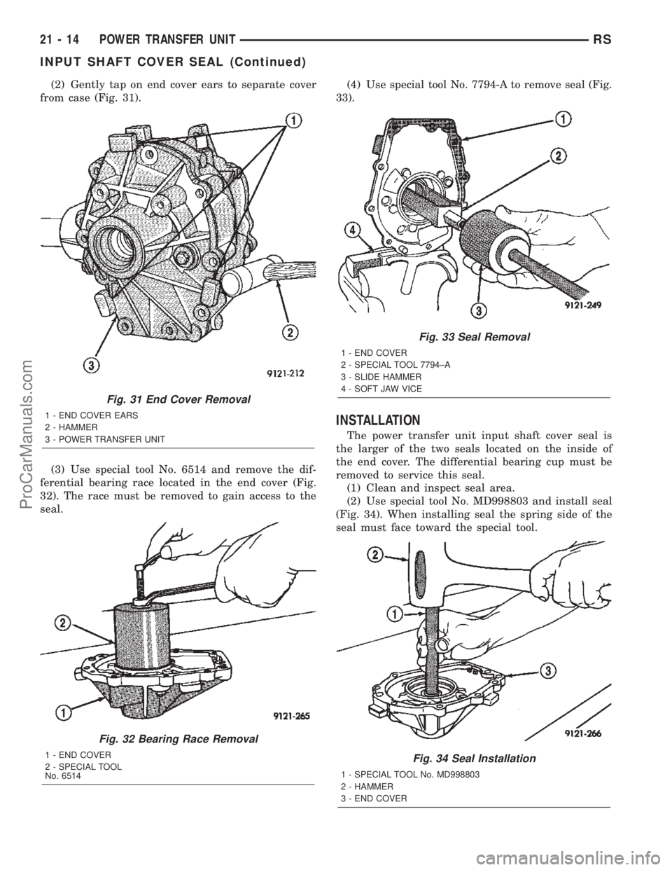
(2) Gently tap on end cover ears to separate cover
from case (Fig. 31).
(3) Use special tool No. 6514 and remove the dif-
ferential bearing race located in the end cover (Fig.
32). The race must be removed to gain access to the
seal.(4) Use special tool No. 7794-A to remove seal (Fig.
33).
INSTALLATION
The power transfer unit input shaft cover seal is
the larger of the two seals located on the inside of
the end cover. The differential bearing cup must be
removed to service this seal.
(1) Clean and inspect seal area.
(2) Use special tool No. MD998803 and install seal
(Fig. 34). When installing seal the spring side of the
seal must face toward the special tool.
Fig. 31 End Cover Removal
1 - END COVER EARS
2 - HAMMER
3 - POWER TRANSFER UNIT
Fig. 32 Bearing Race Removal
1 - END COVER
2 - SPECIAL TOOL
No. 6514
Fig. 33 Seal Removal
1 - END COVER
2 - SPECIAL TOOL 7794±A
3 - SLIDE HAMMER
4 - SOFT JAW VICE
Fig. 34 Seal Installation
1 - SPECIAL TOOL No. MD998803
2 - HAMMER
3 - END COVER
21 - 14 POWER TRANSFER UNITRS
INPUT SHAFT COVER SEAL (Continued)
ProCarManuals.com
Page 1574 of 2399
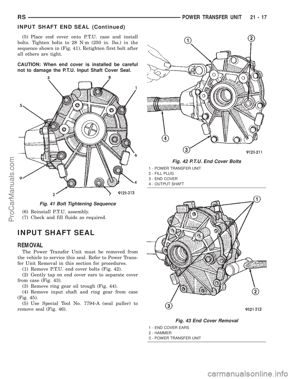
(5) Place end cover onto P.T.U. case and install
bolts. Tighten bolts to 28 N´m (250 in. lbs.) in the
sequence shown in (Fig. 41). Retighten first bolt after
all others are tight.
CAUTION: When end cover is installed be careful
not to damage the P.T.U. Input Shaft Cover Seal.
(6) Reinstall P.T.U. assembly.
(7) Check and fill fluids as required.
INPUT SHAFT SEAL
REMOVAL
The Power Transfer Unit must be removed from
the vehicle to service this seal. Refer to Power Trans-
fer Unit Removal in this section for procedures.
(1) Remove P.T.U. end cover bolts (Fig. 42).
(2) Gently tap on end cover ears to separate cover
from case (Fig. 43).
(3) Remove ring gear oil trough (Fig. 44).
(4) Remove input shaft and ring gear from case
(Fig. 45).
(5) Use Special Tool No. 7794-A (seal puller) to
remove seal (Fig. 46).
Fig. 41 Bolt Tightening Sequence
Fig. 42 P.T.U. End Cover Bolts
1 - POWER TRANSFER UNIT
2 - FILL PLUG
3 - END COVER
4 - OUTPUT SHAFT
Fig. 43 End Cover Removal
1 - END COVER EARS
2 - HAMMER
3 - POWER TRANSFER UNIT
RSPOWER TRANSFER UNIT21-17
INPUT SHAFT END SEAL (Continued)
ProCarManuals.com