2002 CHRYSLER CARAVAN manual transmission
[x] Cancel search: manual transmissionPage 1888 of 2399
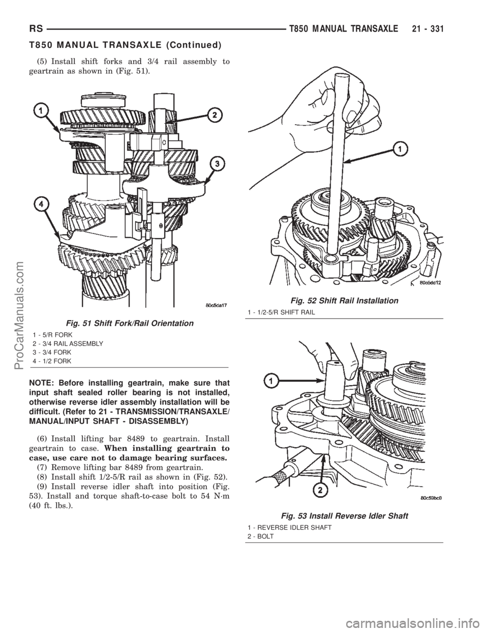
(5) Install shift forks and 3/4 rail assembly to
geartrain as shown in (Fig. 51).
NOTE: Before installing geartrain, make sure that
input shaft sealed roller bearing is not installed,
otherwise reverse idler assembly installation will be
difficult. (Refer to 21 - TRANSMISSION/TRANSAXLE/
MANUAL/INPUT SHAFT - DISASSEMBLY)
(6) Install lifting bar 8489 to geartrain. Install
geartrain to case.When installing geartrain to
case, use care not to damage bearing surfaces.
(7) Remove lifting bar 8489 from geartrain.
(8) Install shift 1/2-5/R rail as shown in (Fig. 52).
(9) Install reverse idler shaft into position (Fig.
53). Install and torque shaft-to-case bolt to 54 N´m
(40 ft. lbs.).
Fig. 51 Shift Fork/Rail Orientation
1 - 5/R FORK
2 - 3/4 RAIL ASSEMBLY
3 - 3/4 FORK
4 - 1/2 FORK
Fig. 52 Shift Rail Installation
1 - 1/2-5/R SHIFT RAIL
Fig. 53 Install Reverse Idler Shaft
1 - REVERSE IDLER SHAFT
2 - BOLT
RST850 MANUAL TRANSAXLE21 - 331
T850 MANUAL TRANSAXLE (Continued)
ProCarManuals.com
Page 1892 of 2399
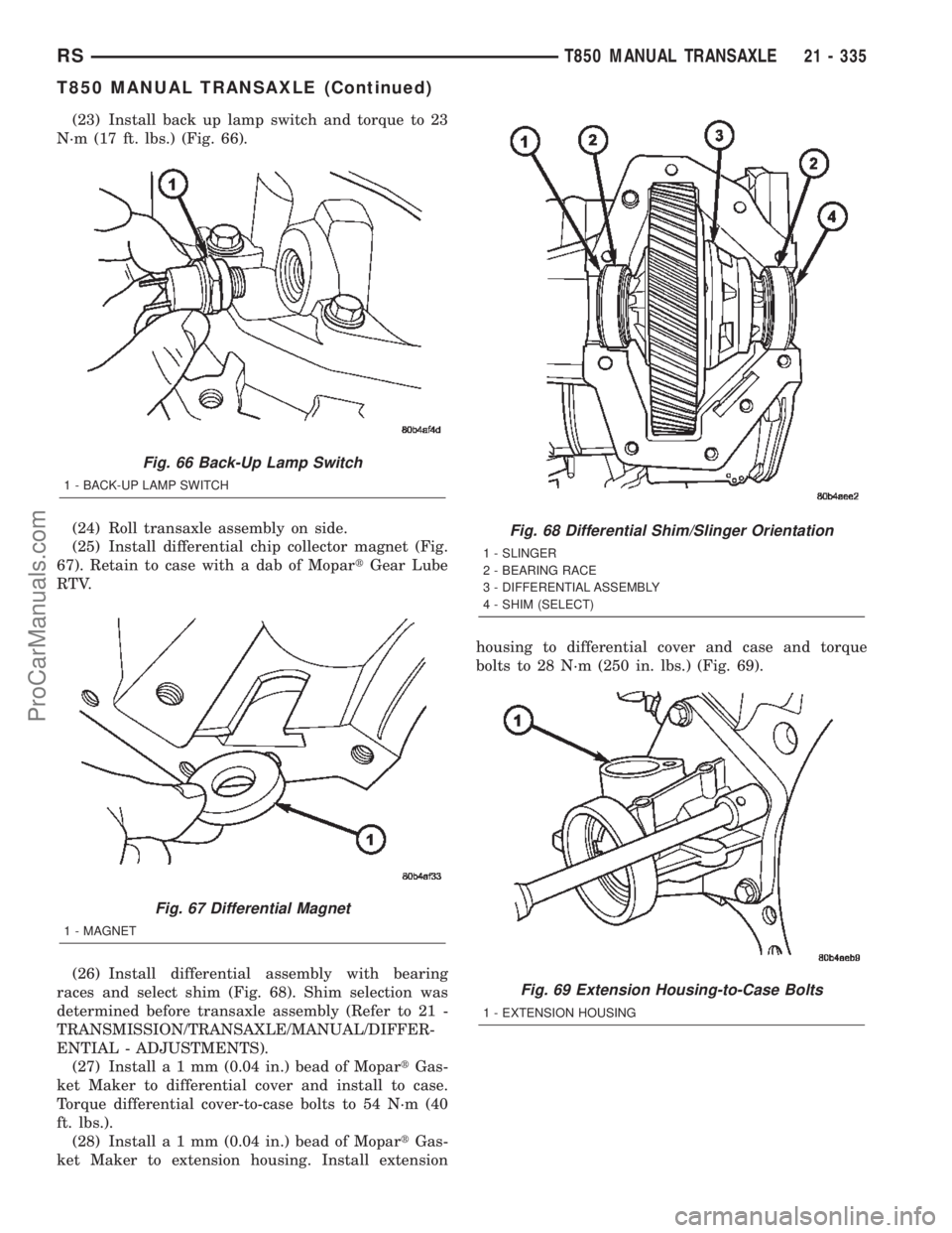
(23) Install back up lamp switch and torque to 23
N´m (17 ft. lbs.) (Fig. 66).
(24) Roll transaxle assembly on side.
(25) Install differential chip collector magnet (Fig.
67). Retain to case with a dab of MopartGear Lube
RTV.
(26) Install differential assembly with bearing
races and select shim (Fig. 68). Shim selection was
determined before transaxle assembly (Refer to 21 -
TRANSMISSION/TRANSAXLE/MANUAL/DIFFER-
ENTIAL - ADJUSTMENTS).
(27) Installa1mm(0.04 in.) bead of MopartGas-
ket Maker to differential cover and install to case.
Torque differential cover-to-case bolts to 54 N´m (40
ft. lbs.).
(28) Installa1mm(0.04 in.) bead of MopartGas-
ket Maker to extension housing. Install extensionhousing to differential cover and case and torque
bolts to 28 N´m (250 in. lbs.) (Fig. 69).
Fig. 66 Back-Up Lamp Switch
1 - BACK-UP LAMP SWITCH
Fig. 67 Differential Magnet
1 - MAGNET
Fig. 68 Differential Shim/Slinger Orientation
1 - SLINGER
2 - BEARING RACE
3 - DIFFERENTIAL ASSEMBLY
4 - SHIM (SELECT)
Fig. 69 Extension Housing-to-Case Bolts
1 - EXTENSION HOUSING
RST850 MANUAL TRANSAXLE21 - 335
T850 MANUAL TRANSAXLE (Continued)
ProCarManuals.com
Page 1900 of 2399
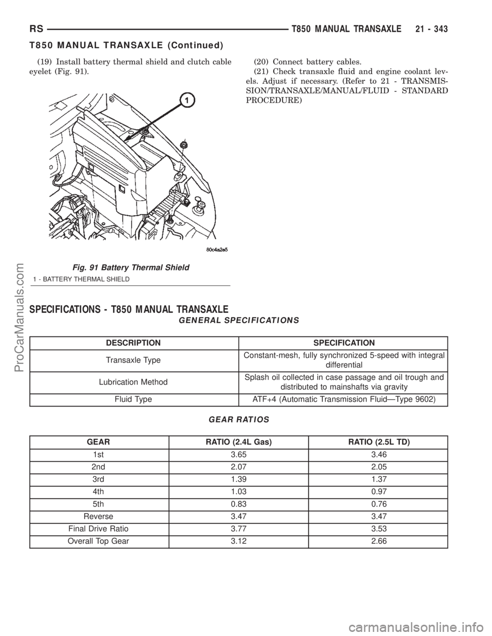
(19) Install battery thermal shield and clutch cable
eyelet (Fig. 91).(20) Connect battery cables.
(21) Check transaxle fluid and engine coolant lev-
els. Adjust if necessary. (Refer to 21 - TRANSMIS-
SION/TRANSAXLE/MANUAL/FLUID - STANDARD
PROCEDURE)
SPECIFICATIONS - T850 MANUAL TRANSAXLE
GENERAL SPECIFICATIONS
DESCRIPTION SPECIFICATION
Transaxle TypeConstant-mesh, fully synchronized 5-speed with integral
differential
Lubrication MethodSplash oil collected in case passage and oil trough and
distributed to mainshafts via gravity
Fluid Type ATF+4 (Automatic Transmission FluidÐType 9602)
GEAR RATIOS
GEAR RATIO (2.4L Gas) RATIO (2.5L TD)
1st 3.65 3.46
2nd 2.07 2.05
3rd 1.39 1.37
4th 1.03 0.97
5th 0.83 0.76
Reverse 3.47 3.47
Final Drive Ratio 3.77 3.53
Overall Top Gear 3.12 2.66
Fig. 91 Battery Thermal Shield
1 - BATTERY THERMAL SHIELD
RST850 MANUAL TRANSAXLE21 - 343
T850 MANUAL TRANSAXLE (Continued)
ProCarManuals.com
Page 1905 of 2399
AXLE SEALS
REMOVAL
(1) Raise vehicle on hoist.
(2) Remove one or both front halfshaft assemblies.
(Refer to 3 - DIFFERENTIAL & DRIVELINE/HALF
SHAFT - REMOVAL)
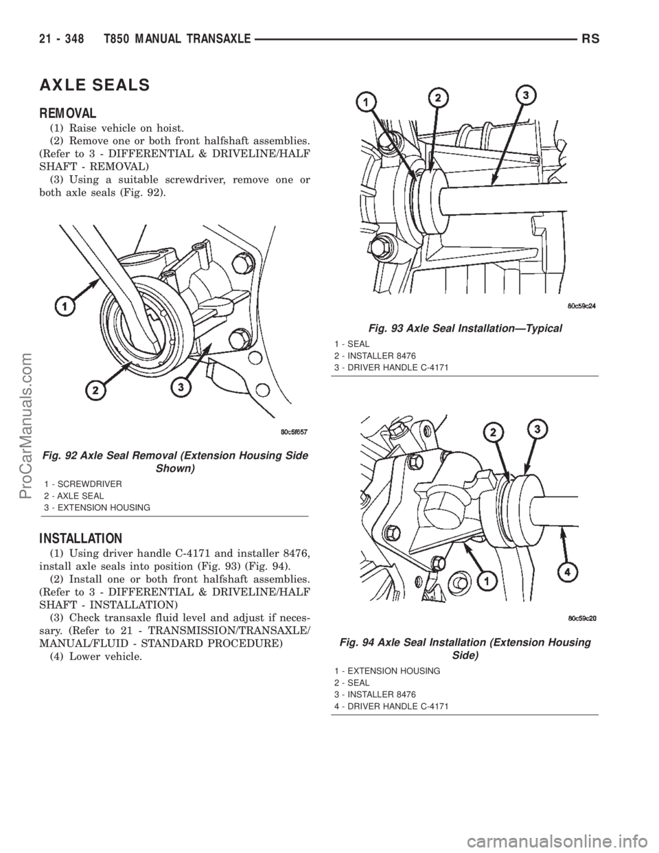
(3) Using a suitable screwdriver, remove one or
both axle seals (Fig. 92).
INSTALLATION
(1) Using driver handle C-4171 and installer 8476,
install axle seals into position (Fig. 93) (Fig. 94).
(2) Install one or both front halfshaft assemblies.
(Refer to 3 - DIFFERENTIAL & DRIVELINE/HALF
SHAFT - INSTALLATION)
(3) Check transaxle fluid level and adjust if neces-
sary. (Refer to 21 - TRANSMISSION/TRANSAXLE/
MANUAL/FLUID - STANDARD PROCEDURE)
(4) Lower vehicle.
Fig. 92 Axle Seal Removal (Extension Housing Side
Shown)
1 - SCREWDRIVER
2 - AXLE SEAL
3 - EXTENSION HOUSING
Fig. 93 Axle Seal InstallationÐTypical
1 - SEAL
2 - INSTALLER 8476
3 - DRIVER HANDLE C-4171
Fig. 94 Axle Seal Installation (Extension Housing
Side)
1 - EXTENSION HOUSING
2 - SEAL
3 - INSTALLER 8476
4 - DRIVER HANDLE C-4171
21 - 348 T850 MANUAL TRANSAXLERS
ProCarManuals.com
Page 1913 of 2399
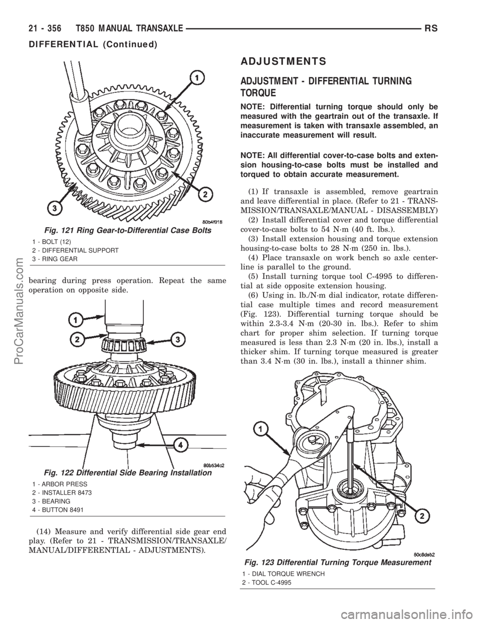
bearing during press operation. Repeat the same
operation on opposite side.
(14) Measure and verify differential side gear end
play. (Refer to 21 - TRANSMISSION/TRANSAXLE/
MANUAL/DIFFERENTIAL - ADJUSTMENTS).
ADJUSTMENTS
ADJUSTMENT - DIFFERENTIAL TURNING
TORQUE
NOTE: Differential turning torque should only be
measured with the geartrain out of the transaxle. If
measurement is taken with transaxle assembled, an
inaccurate measurement will result.
NOTE: All differential cover-to-case bolts and exten-
sion housing-to-case bolts must be installed and
torqued to obtain accurate measurement.
(1) If transaxle is assembled, remove geartrain
and leave differential in place. (Refer to 21 - TRANS-
MISSION/TRANSAXLE/MANUAL - DISASSEMBLY)
(2) Install differential cover and torque differential
cover-to-case bolts to 54 N´m (40 ft. lbs.).
(3) Install extension housing and torque extension
housing-to-case bolts to 28 N´m (250 in. lbs.).
(4) Place transaxle on work bench so axle center-
line is parallel to the ground.
(5) Install turning torque tool C-4995 to differen-
tial at side opposite extension housing.
(6) Using in. lb./N´m dial indicator, rotate differen-
tial case multiple times and record measurement
(Fig. 123). Differential turning torque should be
within 2.3-3.4 N´m (20-30 in. lbs.). Refer to shim
chart for proper shim selection. If turning torque
measured is less than 2.3 N´m (20 in. lbs.), install a
thicker shim. If turning torque measured is greater
than 3.4 N´m (30 in. lbs.), install a thinner shim.
Fig. 123 Differential Turning Torque Measurement
1 - DIAL TORQUE WRENCH
2 - TOOL C-4995
Fig. 121 Ring Gear-to-Differential Case Bolts
1 - BOLT (12)
2 - DIFFERENTIAL SUPPORT
3 - RING GEAR
Fig. 122 Differential Side Bearing Installation
1 - ARBOR PRESS
2 - INSTALLER 8473
3 - BEARING
4 - BUTTON 8491
21 - 356 T850 MANUAL TRANSAXLERS
DIFFERENTIAL (Continued)
ProCarManuals.com
Page 1915 of 2399
ADJUSTMENT - DIFFERENTIAL SIDE GEAR
END PLAY
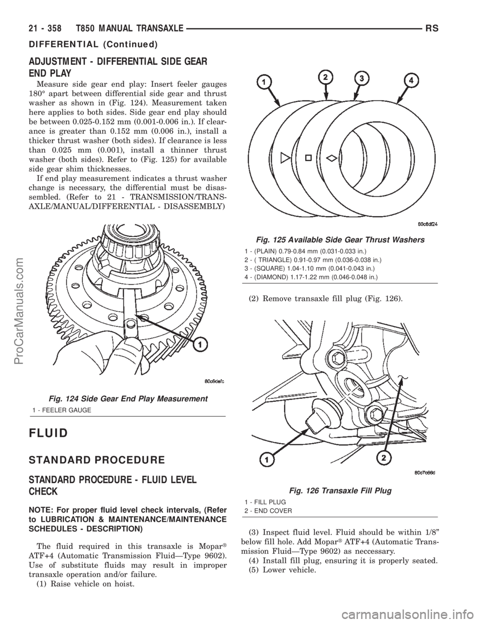
Measure side gear end play: Insert feeler gauges
180É apart between differential side gear and thrust
washer as shown in (Fig. 124). Measurement taken
here applies to both sides. Side gear end play should
be between 0.025-0.152 mm (0.001-0.006 in.). If clear-
ance is greater than 0.152 mm (0.006 in.), install a
thicker thrust washer (both sides). If clearance is less
than 0.025 mm (0.001), install a thinner thrust
washer (both sides). Refer to (Fig. 125) for available
side gear shim thicknesses.
If end play measurement indicates a thrust washer
change is necessary, the differential must be disas-
sembled. (Refer to 21 - TRANSMISSION/TRANS-
AXLE/MANUAL/DIFFERENTIAL - DISASSEMBLY)
FLUID
STANDARD PROCEDURE
STANDARD PROCEDURE - FLUID LEVEL
CHECK
NOTE: For proper fluid level check intervals, (Refer
to LUBRICATION & MAINTENANCE/MAINTENANCE
SCHEDULES - DESCRIPTION)
The fluid required in this transaxle is Mopart
ATF+4 (Automatic Transmission FluidÐType 9602).
Use of substitute fluids may result in improper
transaxle operation and/or failure.
(1) Raise vehicle on hoist.(2) Remove transaxle fill plug (Fig. 126).
(3) Inspect fluid level. Fluid should be within 1/8º
below fill hole. Add MopartATF+4 (Automatic Trans-
mission FluidÐType 9602) as neccessary.
(4) Install fill plug, ensuring it is properly seated.
(5) Lower vehicle.
Fig. 124 Side Gear End Play Measurement
1 - FEELER GAUGE
Fig. 125 Available Side Gear Thrust Washers
1 - (PLAIN) 0.79-0.84 mm (0.031-0.033 in.)
2 - ( TRIANGLE) 0.91-0.97 mm (0.036-0.038 in.)
3 - (SQUARE) 1.04-1.10 mm (0.041-0.043 in.)
4 - (DIAMOND) 1.17-1.22 mm (0.046-0.048 in.)
Fig. 126 Transaxle Fill Plug
1 - FILL PLUG
2 - END COVER
21 - 358 T850 MANUAL TRANSAXLERS
DIFFERENTIAL (Continued)
ProCarManuals.com
Page 1916 of 2399
STANDARD PROCEDURE - FLUID DRAIN AND
FILL
NOTE: For proper fluid change intervals, (Refer to
LUBRICATION & MAINTENANCE/MAINTENANCE
SCHEDULES - DESCRIPTION)
The fluid required in this transaxle is Mopart
ATF+4 (Automatic Transmission FluidÐType 9602).
Use of substitute fluids may result in improper
transaxle operation and/or failure.
FLUID DRAIN
(1) Raise vehicle on hoist.
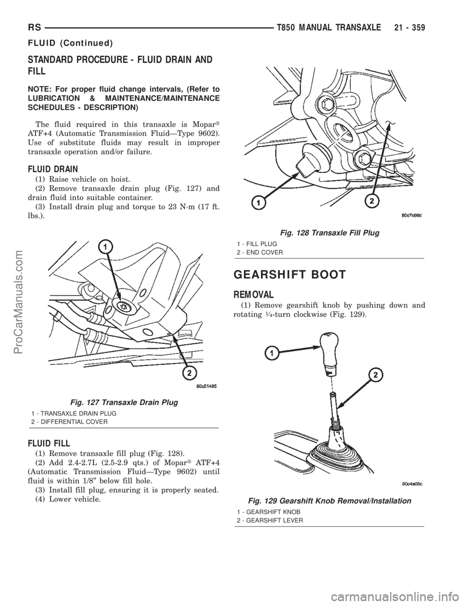
(2) Remove transaxle drain plug (Fig. 127) and
drain fluid into suitable container.
(3) Install drain plug and torque to 23 N´m (17 ft.
lbs.).
FLUID FILL
(1) Remove transaxle fill plug (Fig. 128).
(2) Add 2.4-2.7L (2.5-2.9 qts.) of MopartATF+4
(Automatic Transmission FluidÐType 9602) until
fluid is within 1/8º below fill hole.
(3) Install fill plug, ensuring it is properly seated.
(4) Lower vehicle.
GEARSHIFT BOOT
REMOVAL
(1) Remove gearshift knob by pushing down and
rotating1¤4-turn clockwise (Fig. 129).
Fig. 127 Transaxle Drain Plug
1 - TRANSAXLE DRAIN PLUG
2 - DIFFERENTIAL COVER
Fig. 128 Transaxle Fill Plug
1 - FILL PLUG
2 - END COVER
Fig. 129 Gearshift Knob Removal/Installation
1 - GEARSHIFT KNOB
2 - GEARSHIFT LEVER
RST850 MANUAL TRANSAXLE21 - 359
FLUID (Continued)
ProCarManuals.com
Page 1963 of 2399
Inspect for the following:
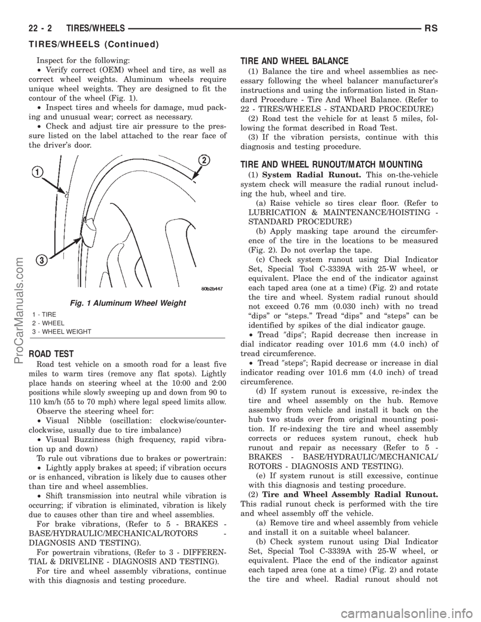
²Verify correct (OEM) wheel and tire, as well as
correct wheel weights. Aluminum wheels require
unique wheel weights. They are designed to fit the
contour of the wheel (Fig. 1).
²Inspect tires and wheels for damage, mud pack-
ing and unusual wear; correct as necessary.
²Check and adjust tire air pressure to the pres-
sure listed on the label attached to the rear face of
the driver's door.
ROAD TEST
Road test vehicle on a smooth road for a least five
miles to warm tires (remove any flat spots). Lightly
place hands on steering wheel at the 10:00 and 2:00
positions while slowly sweeping up and down from 90 to
110 km/h (55 to 70 mph) where legal speed limits allow.
Observe the steering wheel for:
²Visual Nibble (oscillation: clockwise/counter-
clockwise, usually due to tire imbalance)
²Visual Buzziness (high frequency, rapid vibra-
tion up and down)
To rule out vibrations due to brakes or powertrain:
²Lightly apply brakes at speed; if vibration occurs
or is enhanced, vibration is likely due to causes other
than tire and wheel assemblies.
²
Shift transmission into neutral while vibration is
occurring; if vibration is eliminated, vibration is likely
due to causes other than tire and wheel assemblies.
For brake vibrations, (Refer to 5 - BRAKES -
BASE/HYDRAULIC/MECHANICAL/ROTORS -
DIAGNOSIS AND TESTING).
For powertrain vibrations, (Refer to 3 - DIFFEREN-
TIAL & DRIVELINE - DIAGNOSIS AND TESTING).
For tire and wheel assembly vibrations, continue
with this diagnosis and testing procedure.
TIRE AND WHEEL BALANCE
(1) Balance the tire and wheel assemblies as nec-
essary following the wheel balancer manufacturer's
instructions and using the information listed in Stan-
dard Procedure - Tire And Wheel Balance. (Refer to
22 - TIRES/WHEELS - STANDARD PROCEDURE)
(2) Road test the vehicle for at least 5 miles, fol-
lowing the format described in Road Test.
(3) If the vibration persists, continue with this
diagnosis and testing procedure.
TIRE AND WHEEL RUNOUT/MATCH MOUNTING
(1)System Radial Runout.This on-the-vehicle
system check will measure the radial runout includ-
ing the hub, wheel and tire.
(a) Raise vehicle so tires clear floor. (Refer to
LUBRICATION & MAINTENANCE/HOISTING -
STANDARD PROCEDURE)
(b) Apply masking tape around the circumfer-
ence of the tire in the locations to be measured
(Fig. 2). Do not overlap the tape.
(c) Check system runout using Dial Indicator
Set, Special Tool C-3339A with 25-W wheel, or
equivalent. Place the end of the indicator against
each taped area (one at a time) (Fig. 2) and rotate
the tire and wheel. System radial runout should
not exceed 0.76 mm (0.030 inch) with no tread
ªdipsº or ªsteps.º Tread ªdipsº and ªstepsº can be
identified by spikes of the dial indicator gauge.
²Tread9dips9; Rapid decrease then increase in
dial indicator reading over 101.6 mm (4.0 inch) of
tread circumference.
²Tread9steps9; Rapid decrease or increase in dial
indicator reading over 101.6 mm (4.0 inch) of tread
circumference.
(d) If system runout is excessive, re-index the
tire and wheel assembly on the hub. Remove
assembly from vehicle and install it back on the
hub two studs over from original mounting posi-
tion. If re-indexing the tire and wheel assembly
corrects or reduces system runout, check hub
runout and repair as necessary (Refer to 5 -
BRAKES - BASE/HYDRAULIC/MECHANICAL/
ROTORS - DIAGNOSIS AND TESTING).
(e) If system runout is still excessive, continue
with this diagnosis and testing procedure.
(2)Tire and Wheel Assembly Radial Runout.
This radial runout check is performed with the tire
and wheel assembly off the vehicle.
(a) Remove tire and wheel assembly from vehicle
and install it on a suitable wheel balancer.
(b) Check system runout using Dial Indicator
Set, Special Tool C-3339A with 25-W wheel, or
equivalent. Place the end of the indicator against
each taped area (one at a time) (Fig. 2) and rotate
the tire and wheel. Radial runout should not
Fig. 1 Aluminum Wheel Weight
1 - TIRE
2 - WHEEL
3 - WHEEL WEIGHT
22 - 2 TIRES/WHEELSRS
TIRES/WHEELS (Continued)
ProCarManuals.com