Page 1864 of 2399

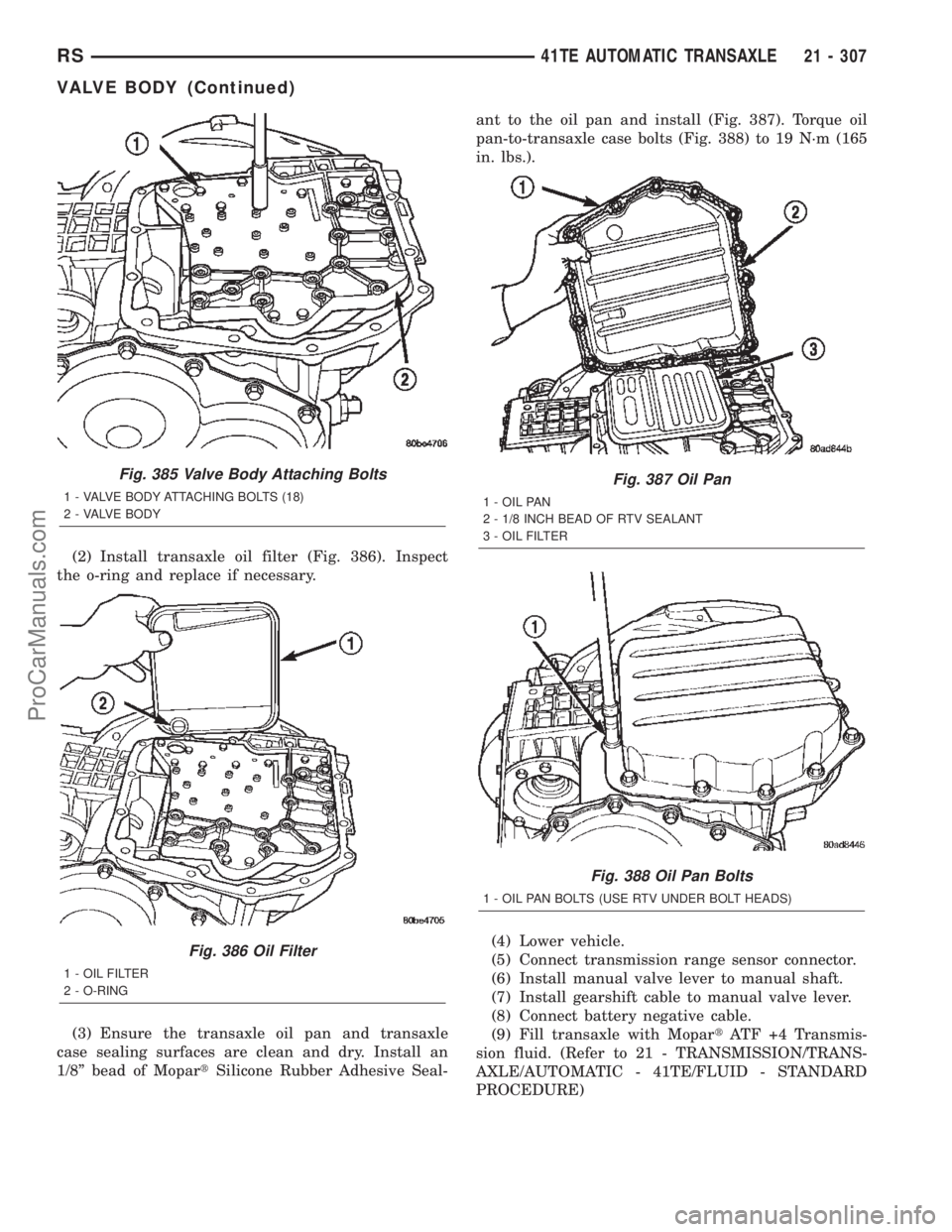
(2) Install transaxle oil filter (Fig. 386). Inspect
the o-ring and replace if necessary.
(3) Ensure the transaxle oil pan and transaxle
case sealing surfaces are clean and dry. Install an
1/8º bead of MopartSilicone Rubber Adhesive Seal-ant to the oil pan and install (Fig. 387). Torque oil
pan-to-transaxle case bolts (Fig. 388) to 19 N´m (165
in. lbs.).
(4) Lower vehicle.
(5) Connect transmission range sensor connector.
(6) Install manual valve lever to manual shaft.
(7) Install gearshift cable to manual valve lever.
(8) Connect battery negative cable.
(9) Fill transaxle with MopartATF +4 Transmis-
sion fluid. (Refer to 21 - TRANSMISSION/TRANS-
AXLE/AUTOMATIC - 41TE/FLUID - STANDARD
PROCEDURE)
Fig. 385 Valve Body Attaching Bolts
1 - VALVE BODY ATTACHING BOLTS (18)
2 - VALVE BODY
Fig. 386 Oil Filter
1 - OIL FILTER
2 - O-RING
Fig. 387 Oil Pan
1 - OIL PAN
2 - 1/8 INCH BEAD OF RTV SEALANT
3 - OIL FILTER
Fig. 388 Oil Pan Bolts
1 - OIL PAN BOLTS (USE RTV UNDER BOLT HEADS)
RS41TE AUTOMATIC TRANSAXLE21 - 307
VALVE BODY (Continued)
ProCarManuals.com
Page 1876 of 2399

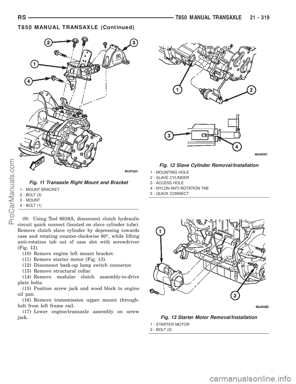
(9) Using Tool 6638A, disconnect clutch hydraulic
circuit quick connect (located on slave cylinder tube).
Remove clutch slave cylinder by depressing towards
case and rotating counter-clockwise 60É, while lifting
anti-rotation tab out of case slot with screwdriver
(Fig. 12).
(10) Remove engine left mount bracket.
(11) Remove starter motor (Fig. 13).
(12) Disconnect back-up lamp switch connector.
(13) Remove structural collar.
(14) Remove modular clutch assembly-to-drive
plate bolts.
(15) Position screw jack and wood block to engine
oil pan.
(16) Remove transmission upper mount through-
bolt from left frame rail.
(17) Lower engine/transaxle assembly on screw
jack.
Fig. 11 Transaxle Right Mount and Bracket
1 - MOUNT BRACKET
2 - BOLT (3)
3 - MOUNT
4 - BOLT (1)
Fig. 12 Slave Cylinder Removal/Installation
1 - MOUNTING HOLE
2 - SLAVE CYLINDER
3 - ACCESS HOLE
4 - NYLON ANTI-ROTATION TAB
5 - QUICK CONNECT
Fig. 13 Starter Motor Removal/Installation
1 - STARTER MOTOR
2 - BOLT (3)
RST850 MANUAL TRANSAXLE21 - 319
T850 MANUAL TRANSAXLE (Continued)
ProCarManuals.com
Page 1877 of 2399
(18) Remove four (4) upper mount-to-transaxle
bolts and remove mount (Fig. 14).
(19) Obtain helper and transmission jack. Secure
transaxle to transmission jack and remove transaxle-
to-engine bolts.
(20) Remove transaxle from engine.
(21) Inspect modular clutch assembly, clutch
release components, and engine drive plate.
REMOVAL - 2.5L TD
(1) Raise hood.
(2) Disconnect both battery cables.
(3) Remove battery thermal shield (Fig. 15).
(4) Remove battery hold down bolt, clamp, and
battery (Fig. 16).
Fig. 14 Transaxle Upper Mount
1 - MOUNT
2 - BOLT (4)
Fig. 15 Battery Thermal Shield
1 - BATTERY THERMAL SHIELD
Fig. 16 Battery and Hold-Down Clamp
1 - BATTERY
2 - HOLD-DOWN CLAMP
21 - 320 T850 MANUAL TRANSAXLERS
T850 MANUAL TRANSAXLE (Continued)
ProCarManuals.com
Page 1879 of 2399

(11) Raise vehicle on hoist.
(12) Remove front wheel/tires and halfshafts.
(13) Remove underbody splash shield.
(14) Drain transaxle fluid into suitable container.
(15) Remove front harness retainer and secure
harness out of way.
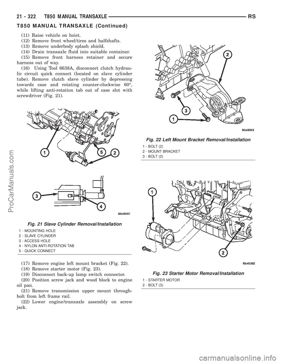
(16) Using Tool 6638A, disconnect clutch hydrau-
lic circuit quick connect (located on slave cylinder
tube). Remove clutch slave cylinder by depressing
towards case and rotating counter-clockwise 60É,
while lifting anti-rotation tab out of case slot with
screwdriver (Fig. 21).
(17) Remove engine left mount bracket (Fig. 22).
(18) Remove starter motor (Fig. 23).
(19) Disconnect back-up lamp switch connector.
(20) Position screw jack and wood block to engine
oil pan.
(21) Remove transmission upper mount through-
bolt from left frame rail.
(22) Lower engine/transaxle assembly on screw
jack.
Fig. 21 Slave Cylinder Removal/Installation
1 - MOUNTING HOLE
2 - SLAVE CYLINDER
3 - ACCESS HOLE
4 - NYLON ANTI-ROTATION TAB
5 - QUICK CONNECT
Fig. 22 Left Mount Bracket Removal/Installation
1 - BOLT (2)
2 - MOUNT BRACKET
3 - BOLT (2)
Fig. 23 Starter Motor Removal/Installation
1 - STARTER MOTOR
2 - BOLT (3)
21 - 322 T850 MANUAL TRANSAXLERS
T850 MANUAL TRANSAXLE (Continued)
ProCarManuals.com
Page 1880 of 2399
(23) Remove four (4) upper mount-to-transaxle
bolts and remove mount (Fig. 24).
(24) Obtain helper and transmission jack. Secure
transaxle to transmission jack and remove transaxle-
to-engine bolts.
(25) Remove transaxle from engine (Fig. 25).
(26) Inspect clutch, clutch release components, and
flywheel.DISASSEMBLY
(1) Remove clutch release lever and bearing (Fig.
26). Inspect release lever pivot balls and replace if
necessary (Fig. 27). Use slide hammer C-3752 and
remover/installer 6891 (Fig. 28) if pivot ball replace-
ment is necessary.
Fig. 25 Transaxle Removal/Installation
1 - TRANSAXLE
2 - BOLT
Fig. 24 Transaxle Upper Mount
1 - MOUNT
2 - BOLT (4)
Fig. 26 Release Bearing and Lever
1 - RELEASE LEVER
2 - RELEASE BEARING
RST850 MANUAL TRANSAXLE21 - 323
T850 MANUAL TRANSAXLE (Continued)
ProCarManuals.com
Page 1884 of 2399

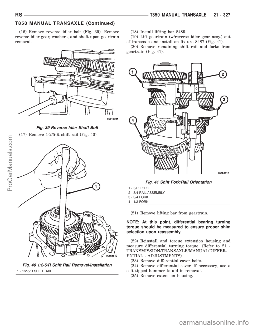
(16) Remove reverse idler bolt (Fig. 39). Remove
reverse idler gear, washers, and shaft upon geartrain
removal.
(17) Remove 1-2/5-R shift rail (Fig. 40).(18) Install lifting bar 8489.
(19) Lift geartrain (w/reverse idler gear assy.) out
of transaxle and install on fixture 8487 (Fig. 41).
(20) Remove remaining shift rail and forks from
geartrain (Fig. 41).
(21) Remove lifting bar from geartrain.
NOTE: At this point, differential bearing turning
torque should be measured to ensure proper shim
selection upon reassembly.
(22) Reinstall and torque extension housing and
measure differential turning torque. (Refer to 21 -
TRANSMISSION/TRANSAXLE/MANUAL/DIFFER-
ENTIAL - ADJUSTMENTS)
(23) Remove differential cover bolts.
(24) Remove differential cover. If necessary, use a
soft tipped hammer to aid in removal.
(25) Remove extension housing.
Fig. 39 Reverse Idler Shaft Bolt
Fig. 40 1/2-5/R Shift Rail Removal/Installation
1 - 1/2-5/R SHIFT RAIL
Fig. 41 Shift Fork/Rail Orientation
1 - 5/R FORK
2 - 3/4 RAIL ASSEMBLY
3 - 3/4 FORK
4 - 1/2 FORK
RST850 MANUAL TRANSAXLE21 - 327
T850 MANUAL TRANSAXLE (Continued)
ProCarManuals.com
Page 1886 of 2399
(30) Remove input shaft bearing using an arbor
press and tool 8474 (Fig. 46).
ASSEMBLY
NOTE: When assembling this transaxle, always use
NEW snap rings.
NOTE: Before assembling transaxle, differential
turning torque must be measured and adjusted.
(Refer to 21 - TRANSMISSION/TRANSAXLE/MANU-
AL/DIFFERENTIAL - ADJUSTMENTS). Differential
turning torque must be measured with geartrain out
of case.
(1) Install input shaft bearing using an arbor press
and remover/installer 8474 (Fig. 47).
(2) Install shift shaft bushing to case using
installer 8475 (Fig. 48).
Fig. 46 Input Shaft Bearing Removal
1 - ARBOR PRESS
2 - DRIVER HANDLE C-4171
3 - REMOVER/INSTALLER 8474
Fig. 47 Input Shaft Bearing Installation
1 - ARBOR PRESS
2 - C-4171 DRIVER HANDLE
3 - REMOVER/INSTALLER 8474
4 - INPUT SHAFT BEARING
Fig. 48 Shift Shaft Bushing Installation
1 - INSTALLER 8475
2 - SHIFT SHAFT BUSHING
RST850 MANUAL TRANSAXLE21 - 329
T850 MANUAL TRANSAXLE (Continued)
ProCarManuals.com
Page 1887 of 2399
(3) Install intermediate shaft bearing race to case
with an arbor press, driver handle C-4171, and
installer 8471 (Fig. 49). Press until installer 8471
bottoms on transaxle case.NOTE: If input shaft assembly was not disassem-
bled, it is necessary to remove input shaft sealed
ball bearing before assembling transaxle. (Refer to
21 - TRANSMISSION/TRANSAXLE/MANUAL/INPUT
SHAFT - DISASSEMBLY)
(4) Install assembled input and intermediate
shafts to fixture 8487 (Fig. 50).
Fig. 49 Install Intermediate Shaft Bearing Race
1 - ARBOR PRESS
2 - DRIVER HANDLE C-4171
3 - INSTALLER 8471
4 - INTERMEDIATE SHAFT BEARING RACE
Fig. 50 Install Geartrain to Fixture 8487
1 - INTERMEDIATE SHAFT
2 - INPUT SHAFT
2 - FIXTURE 8487
21 - 330 T850 MANUAL TRANSAXLERS
T850 MANUAL TRANSAXLE (Continued)
ProCarManuals.com