2002 CHRYSLER CARAVAN set clock
[x] Cancel search: set clockPage 1691 of 2399
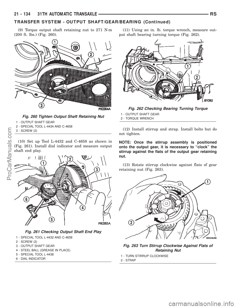
(9) Torque output shaft retaining nut to 271 N´m
(200 ft. lbs.) (Fig. 260).
(10) Set up Tool L-4432 and C-4658 as shown in
(Fig. 261). Install dial indicator and measure output
shaft end play.(11) Using an in. lb. torque wrench, measure out-
put shaft bearing turning torque (Fig. 262).
(12) Install stirrup and strap. Install bolts but do
not tighten.
NOTE: Once the stirrup assembly is positioned
onto the output gear, it is necessary to ªclockº the
stirrup against the flats of the output gear retaining
nut.
(13) Rotate stirrup clockwise against flats of gear
retaining nut (Fig. 263).
Fig. 260 Tighten Output Shaft Retaining Nut
1 - OUTPUT SHAFT GEAR
2 - SPECIAL TOOL L-4434 AND C-4658
3 - SCREW (2)
Fig. 261 Checking Output Shaft End Play
1 - SPECIAL TOOL L-4432 AND C-4658
2 - SCREW (2)
3 - OUTPUT SHAFT GEAR
4 - STEEL BALL (GREASE IN PLACE)
5 - SPECIAL TOOL L-4438
6 - DIAL INDICATOR
Fig. 262 Checking Bearing Turning Torque
1 - OUTPUT SHAFT GEAR
2 - TORQUE WRENCH
Fig. 263 Turn Stirrup Clockwise Against Flats of
Retaining Nut
1 - TURN STIRRUP CLOCKWISE
2 - STRAP
21 - 134 31TH AUTOMATIC TRANSAXLERS
TRANSFER SYSTEM - OUTPUT SHAFT/GEAR/BEARING (Continued)
ProCarManuals.com
Page 1701 of 2399
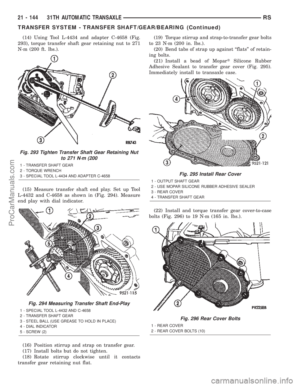
(14) Using Tool L-4434 and adapter C-4658 (Fig.
293), torque transfer shaft gear retaining nut to 271
N´m (200 ft. lbs.).
(15) Measure transfer shaft end play. Set up Tool
L-4432 and C-4658 as shown in (Fig. 294). Measure
end play with dial indicator.
(16) Position stirrup and strap on transfer gear.
(17) Install bolts but do not tighten.
(18) Rotate stirrup clockwise until it contacts
transfer gear retaining nut flat.(19) Torque stirrup and strap-to-transfer gear bolts
to 23 N´m (200 in. lbs.).
(20) Bend tabs of strap up against ªflatsº of retain-
ing bolts.
(21) Install a bead of MopartSilicone Rubber
Adhesive Sealant to transfer gear cover (Fig. 295).
Immediately install to transaxle case.
(22) Install and torque transfer gear cover-to-case
bolts (Fig. 296) to 19 N´m (165 in. lbs.).
Fig. 293 Tighten Transfer Shaft Gear Retaining Nut
to 271 N´m (200
1 - TRANSFER SHAFT GEAR
2 - TORQUE WRENCH
3 - SPECIAL TOOL L-4434 AND ADAPTER C-4658
Fig. 294 Measuring Transfer Shaft End-Play
1 - SPECIAL TOOL L-4432 AND C-4658
2 - TRANSFER SHAFT GEAR
3 - STEEL BALL (USE GREASE TO HOLD IN PLACE)
4 - DIAL INDICATOR
5 - SCREW (2)
Fig. 295 Install Rear Cover
1 - OUTPUT SHAFT GEAR
2 - USE MOPAR SILICONE RUBBER ADHESIVE SEALER
3 - REAR COVER
4 - TRANSFER SHAFT GEAR
Fig. 296 Rear Cover Bolts
1 - REAR COVER
2 - REAR COVER BOLTS (10)
21 - 144 31TH AUTOMATIC TRANSAXLERS
TRANSFER SYSTEM - TRANSFER SHAFT/GEAR/BEARING (Continued)
ProCarManuals.com
Page 1717 of 2399
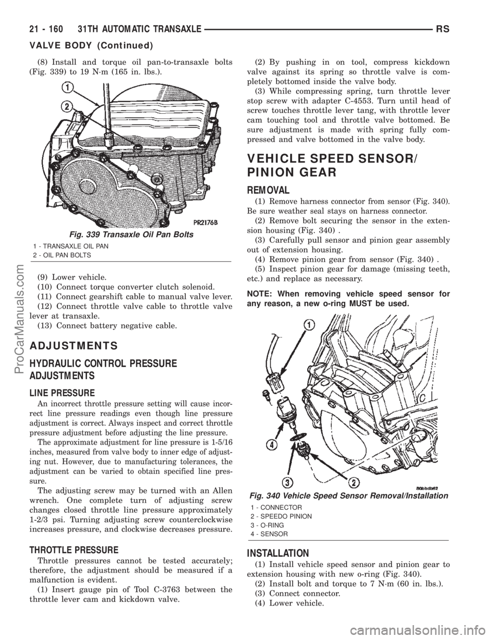
(8) Install and torque oil pan-to-transaxle bolts
(Fig. 339) to 19 N´m (165 in. lbs.).
(9) Lower vehicle.
(10) Connect torque converter clutch solenoid.
(11) Connect gearshift cable to manual valve lever.
(12) Connect throttle valve cable to throttle valve
lever at transaxle.
(13) Connect battery negative cable.
ADJUSTMENTS
HYDRAULIC CONTROL PRESSURE
ADJUSTMENTS
LINE PRESSURE
An incorrect throttle pressure setting will cause incor-
rect line pressure readings even though line pressure
adjustment is correct. Always inspect and correct throttle
pressure adjustment before adjusting the line pressure.
The approximate adjustment for line pressure is 1-5/16
inches, measured from valve body to inner edge of adjust-
ing nut. However, due to manufacturing tolerances, the
adjustment can be varied to obtain specified line pres-
sure.
The adjusting screw may be turned with an Allen
wrench. One complete turn of adjusting screw
changes closed throttle line pressure approximately
1-2/3 psi. Turning adjusting screw counterclockwise
increases pressure, and clockwise decreases pressure.
THROTTLE PRESSURE
Throttle pressures cannot be tested accurately;
therefore, the adjustment should be measured if a
malfunction is evident.
(1) Insert gauge pin of Tool C-3763 between the
throttle lever cam and kickdown valve.(2) By pushing in on tool, compress kickdown
valve against its spring so throttle valve is com-
pletely bottomed inside the valve body.
(3) While compressing spring, turn throttle lever
stop screw with adapter C-4553. Turn until head of
screw touches throttle lever tang, with throttle lever
cam touching tool and throttle valve bottomed. Be
sure adjustment is made with spring fully com-
pressed and valve bottomed in the valve body.
VEHICLE SPEED SENSOR/
PINION GEAR
REMOVAL
(1)Remove harness connector from sensor (Fig. 340).
Be sure weather seal stays on harness connector.
(2) Remove bolt securing the sensor in the exten-
sion housing (Fig. 340) .
(3) Carefully pull sensor and pinion gear assembly
out of extension housing.
(4) Remove pinion gear from sensor (Fig. 340) .
(5) Inspect pinion gear for damage (missing teeth,
etc.) and replace as necessary.
NOTE: When removing vehicle speed sensor for
any reason, a new o-ring MUST be used.
INSTALLATION
(1) Install vehicle speed sensor and pinion gear to
extension housing with new o-ring (Fig. 340).
(2) Install bolt and torque to 7 N´m (60 in. lbs.).
(3) Connect connector.
(4) Lower vehicle.
Fig. 339 Transaxle Oil Pan Bolts
1 - TRANSAXLE OIL PAN
2 - OIL PAN BOLTS
Fig. 340 Vehicle Speed Sensor Removal/Installation
1 - CONNECTOR
2 - SPEEDO PINION
3 - O-RING
4 - SENSOR
21 - 160 31TH AUTOMATIC TRANSAXLERS
VALVE BODY (Continued)
ProCarManuals.com
Page 1963 of 2399
Inspect for the following:
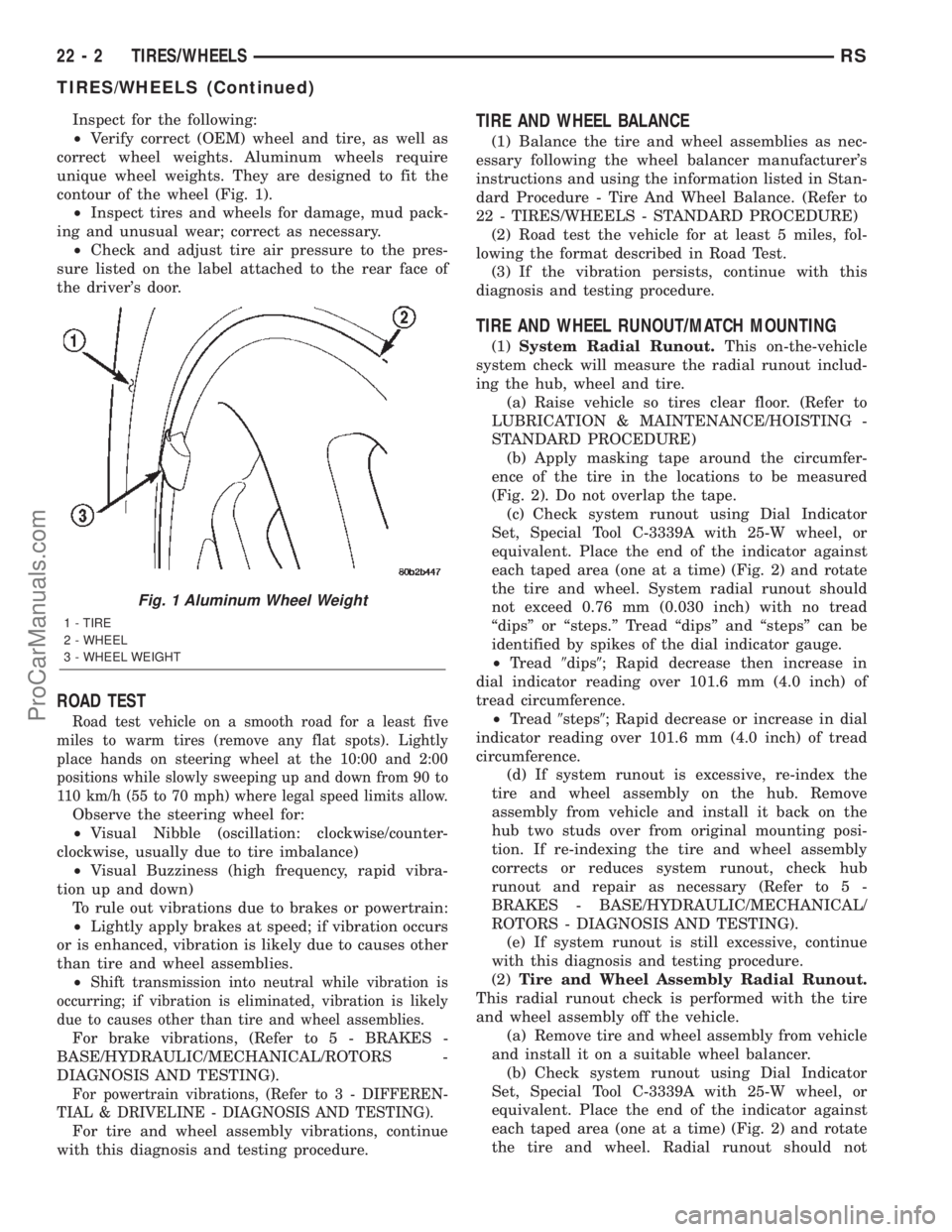
²Verify correct (OEM) wheel and tire, as well as
correct wheel weights. Aluminum wheels require
unique wheel weights. They are designed to fit the
contour of the wheel (Fig. 1).
²Inspect tires and wheels for damage, mud pack-
ing and unusual wear; correct as necessary.
²Check and adjust tire air pressure to the pres-
sure listed on the label attached to the rear face of
the driver's door.
ROAD TEST
Road test vehicle on a smooth road for a least five
miles to warm tires (remove any flat spots). Lightly
place hands on steering wheel at the 10:00 and 2:00
positions while slowly sweeping up and down from 90 to
110 km/h (55 to 70 mph) where legal speed limits allow.
Observe the steering wheel for:
²Visual Nibble (oscillation: clockwise/counter-
clockwise, usually due to tire imbalance)
²Visual Buzziness (high frequency, rapid vibra-
tion up and down)
To rule out vibrations due to brakes or powertrain:
²Lightly apply brakes at speed; if vibration occurs
or is enhanced, vibration is likely due to causes other
than tire and wheel assemblies.
²
Shift transmission into neutral while vibration is
occurring; if vibration is eliminated, vibration is likely
due to causes other than tire and wheel assemblies.
For brake vibrations, (Refer to 5 - BRAKES -
BASE/HYDRAULIC/MECHANICAL/ROTORS -
DIAGNOSIS AND TESTING).
For powertrain vibrations, (Refer to 3 - DIFFEREN-
TIAL & DRIVELINE - DIAGNOSIS AND TESTING).
For tire and wheel assembly vibrations, continue
with this diagnosis and testing procedure.
TIRE AND WHEEL BALANCE
(1) Balance the tire and wheel assemblies as nec-
essary following the wheel balancer manufacturer's
instructions and using the information listed in Stan-
dard Procedure - Tire And Wheel Balance. (Refer to
22 - TIRES/WHEELS - STANDARD PROCEDURE)
(2) Road test the vehicle for at least 5 miles, fol-
lowing the format described in Road Test.
(3) If the vibration persists, continue with this
diagnosis and testing procedure.
TIRE AND WHEEL RUNOUT/MATCH MOUNTING
(1)System Radial Runout.This on-the-vehicle
system check will measure the radial runout includ-
ing the hub, wheel and tire.
(a) Raise vehicle so tires clear floor. (Refer to
LUBRICATION & MAINTENANCE/HOISTING -
STANDARD PROCEDURE)
(b) Apply masking tape around the circumfer-
ence of the tire in the locations to be measured
(Fig. 2). Do not overlap the tape.
(c) Check system runout using Dial Indicator
Set, Special Tool C-3339A with 25-W wheel, or
equivalent. Place the end of the indicator against
each taped area (one at a time) (Fig. 2) and rotate
the tire and wheel. System radial runout should
not exceed 0.76 mm (0.030 inch) with no tread
ªdipsº or ªsteps.º Tread ªdipsº and ªstepsº can be
identified by spikes of the dial indicator gauge.
²Tread9dips9; Rapid decrease then increase in
dial indicator reading over 101.6 mm (4.0 inch) of
tread circumference.
²Tread9steps9; Rapid decrease or increase in dial
indicator reading over 101.6 mm (4.0 inch) of tread
circumference.
(d) If system runout is excessive, re-index the
tire and wheel assembly on the hub. Remove
assembly from vehicle and install it back on the
hub two studs over from original mounting posi-
tion. If re-indexing the tire and wheel assembly
corrects or reduces system runout, check hub
runout and repair as necessary (Refer to 5 -
BRAKES - BASE/HYDRAULIC/MECHANICAL/
ROTORS - DIAGNOSIS AND TESTING).
(e) If system runout is still excessive, continue
with this diagnosis and testing procedure.
(2)Tire and Wheel Assembly Radial Runout.
This radial runout check is performed with the tire
and wheel assembly off the vehicle.
(a) Remove tire and wheel assembly from vehicle
and install it on a suitable wheel balancer.
(b) Check system runout using Dial Indicator
Set, Special Tool C-3339A with 25-W wheel, or
equivalent. Place the end of the indicator against
each taped area (one at a time) (Fig. 2) and rotate
the tire and wheel. Radial runout should not
Fig. 1 Aluminum Wheel Weight
1 - TIRE
2 - WHEEL
3 - WHEEL WEIGHT
22 - 2 TIRES/WHEELSRS
TIRES/WHEELS (Continued)
ProCarManuals.com
Page 2273 of 2399

bezel with the snap clip receptacles on the retainer
above the headliner.
(7) Using hand pressure, press the top edge of the
rear heater-A/C control bezel upward until the two
snap clips are fully seated in their receptacles.
(8) Reconnect the battery negative cable.
(9) Using the DRB-IIItreset the Rear Tempera-
ture Selector calibration values.
(10) Verify that the Actuator Calibration of the
Front Control has passed. If an Actuator Calibration
has not passed correct any errors before proceeding
further.
(11) Rotate the Rear Temperature Selector counter
clockwise to the Cold Position, allow the Selector to
remain in the Cold Position for 5 seconds.
(12) Rotate the Rear Temperature Selector Clock-
wise to the Hot Position, allow the Selector to remain
in the Cold Position for 5 seconds.
(13) calibration is now complete.
BLEND DOOR ACTUATOR
DESCRIPTION
The blend door actuator is a reversible, 12-volt
Direct Current (DC), servo motor (Fig. 3). The single
blend door actuator is located on the outboard side of
the rear heater-A/C unit housing, below the mode
door actuator. The blend door actuator is mechani-
cally connected to the blend air door. The blend door
actuator is interchangeable with the actuator for the
mode door. Each actuator is contained within an
identical black molded plastic housing with an inte-gral wire connector receptacle. Two integral mount-
ing tabs allow the actuator to be secured with two
screws to the rear heater-A/C unit housing. Each
actuator also has an identical output shaft with
splines that connects it to the pivot or linkage of the
proper door. The blend door actuator does not require
mechanical indexing to the blend air door pivot, as it
is electronically calibrated by the front heater-A/C
control module. The blend door actuator cannot be
adjusted or repaired and, if damaged or faulty, it
must be replaced.
OPERATION
The blend door actuator is connected to the front
heater-A/C control module through the vehicle elec-
trical system by a dedicated two-wire take out and
connector of the rear HVAC wire harness. The blend
door actuator can move the blend air door in two
directions. When the front heater-A/C control module
pulls the voltage on one side of the motor connection
Fig. 2 Heater-A/C Control Bezel
1 - BEZEL
2 - SNAP CLIP (2)
3 - HEATER-A/C CONTROL
4 - SCREW (3)
5 - LOCATOR TAB (2)
Fig. 3 Blend Door Actuator
1 - SCREW (2)
2 - MODE DOOR ACTUATOR
3 - SCREW (2)
4 - CONNECTOR
5 - BLEND DOOR ACTUATOR
6 - CONNECTOR
24 - 30 CONTROLS - REARRS
A/C-HEATER CONTROL (Continued)
ProCarManuals.com
Page 2305 of 2399
CAUTION: All tools, including the refrigerant recy-
cling equipment, the manifold gauge set, and test
hoses should be kept clean and dry. Keep the work
area clean. Contamination of the refrigerant system
through careless work habits must be avoided. The
refrigerant system will remain chemically stable as
long as pure, moisture-free R-134a refrigerant and
refrigerant oil is used. Dirt, moisture, or air can
upset this chemical stability. Operational troubles
or serious damage can occur if foreign material is
introduced to the refrigerant system.
COMPRESSOR
DESCRIPTION
The compressor used on this vehicle can be one of
two models, depending upon the air conditioning sys-
tem in the vehicle. All vehicles use the Nippondenso
10S20 compressor. This compressor use an aluminum
swash plate, teflon coated pistons and aluminum
sleeveless cylinder walls. This compressor includes
an integral high pressure relief valve. The compres-
sor is secured low in the right front corner of the
engine compartment to a mounting bracket on the
cylinder block (2.4L engine), or directly to the cylin-
der block (3.3L and 3.8L engines) is integral to the
compressor. This compressor cannot be repaired. If
faulty or damaged, the entire compressor must be
replaced. The compressor clutch, pulley, and clutch
coil are available for service replacement.
OPERATION
The compressor is driven by the engine through an
electric clutch, drive pulley and belt arrangement.
The compressor is lubricated by refrigerant oil that is
circulated throughout the refrigerant system with the
refrigerant. The compressor draws in low-pressure
refrigerant vapor from the evaporator through its
suction port. It then compresses the refrigerant into
a high-pressure, high-temperature refrigerant vapor.
The compressor pumps high-pressure refrigerant
vapor to the condenser through the compressor dis-
charge port. The mechanical high pressure relief
valve is designed to vent refrigerant from the system
to protect against damage to the compressor or other
system components, caused by condenser air flow
restrictions or an overcharge of refrigerant. The valve
only vents enough refrigerant to reduce the system
pressure, then re-seats itself. The valve opens at a
discharge pressure of 3445 to 4135 kPA (500 to 600
psi) or above, and closes when a minimum discharge
pressure of 2756 kPa (400 psi) is reached.
DIAGNOSIS AND TESTING - COMPRESSOR
NOISE DIAGNOSIS
Excessive noise while the air conditioning compres-
sor is operating can be caused by loose compressor
mounts, a loose compressor clutch, or high operating
pressures in the refrigerant system. Verify compres-
sor drive belt condition, proper compressor mounting,
correct refrigerant charge level, and compressor head
pressure before compressor repair is performed.
With the close tolerances within the compressor, it
is possible to experience a temporary lockup. The
longer the compressor is inactive, the more likely the
condition is to occur. This condition is the result of
normal refrigerant migration within the refrigerant
system caused by ambient temperature changes. The
refrigerant migration may wash the refrigerant oil
out of the compressor.
NOTE: Prior to a vehicle being removed from ser-
vice or stored for more than two weeks, the com-
pressor should be operated to ensure adequate
refrigerant oil distribution throughout the system
components. Turn on the air conditioner for a min-
imum of five minutes with outside air and the high-
est blower speed selected.
BELT NOISE
If the compressor drive belt slips at initial start-up,
it does not necessarily mean the compressor has
failed. The following procedure can be used to iden-
tify a compressor drive belt noise problem.
²Start the vehicle and run at idle.
²Turn the air conditioner On and listen for belt
squeal.
²If belt squeal is heard, turn the air conditioner
Off immediately.
If the belt squeal stops when the air conditioner is
turned Off, perform the following repair procedures.
(1) Using an appropriate sized oil filter wrench or
a strap wrench, grasp the outer diameter of the com-
pressor clutch hub. While facing the compressor,
rotate the hub clockwise, then counterclockwise. If
the hub rotates, proceed to the next step. If the hub
will not rotate, the compressor is internally damaged,
and must be replaced.
(2) Turn the hub clockwise five complete revolu-
tions and remove the tool.
(3) Start the vehicle and run at idle.
(4) Turn the air conditioner On. Observe the com-
pressor and the system for normal operation, noting
cooling performance and noise levels. Operate for five
minutes before turning the air conditioner Off. If
acceptable cooling performance is observed during
compressor operation, the compressor does not need
to be replaced.
24 - 62 PLUMBING - FRONTRS
PLUMBING - FRONT (Continued)
ProCarManuals.com
Page 2367 of 2399
chemical reaction takes place. This means the con-
centration of oxygen will be the same downstream as
upstream. The output voltage of the downstream
O2S copies the voltage of the upstream sensor. The
only difference is a time lag (seen by the PCM)
between the switching of the O2S's.
To monitor the system, the number of lean-to-rich
switches of upstream and downstream O2S's is
counted. The ratio of downstream switches to
upstream switches is used to determine whether the
catalyst is operating properly. An effective catalyst
will have fewer downstream switches than it has
upstream switches i.e., a ratio closer to zero. For a
totally ineffective catalyst, this ratio will be one-to-
one, indicating that no oxidation occurs in the device.
The system must be monitored so that when cata-
lyst efficiency deteriorates and exhaust emissions
increase to over the legal limit, the MIL (Check
Engine lamp) will be illuminated.
LEAK DETECTION PUMP MONITOR (if equipped)
The leak detection assembly incorporates two pri-
mary functions: it must detect a leak in the evapora-
tive system and seal the evaporative system so the
leak detection test can be run.
The primary components within the assembly are:
A three port solenoid that activates both of the func-
tions listed above; a pump which contains a switch,
two check valves, a spring/diaphragm, and a canister
vent valve (CVV) seal which contains a spring loaded
vent seal valve.
Immediately after a cold start, between predeter-
mined temperature thresholds limits, the three port
solenoid is briefly energized. This initializes the
pump by drawing air into the pump cavity and also
closes the vent seal. During non test conditions the
vent seal is held open by the pump diaphragm
assembly which pushes it open at the full travel posi-
tion. The vent seal will remain closed while the
pump is cycling due to the reed switch triggering of
the three port solenoid that prevents the diaphragm
assembly from reaching full travel. After the brief
initialization period, the solenoid is de-energized
allowing atmospheric pressure to enter the pump
cavity, thus permitting the spring to drive the dia-
phragm which forces air out of the pump cavity and
into the vent system. When the solenoid is energized
and de energized, the cycle is repeated creating flow
in typical diaphragm pump fashion. The pump is con-
trolled in 2 modes:
Pump Mode:The pump is cycled at a fixed rate to
achieve a rapid pressure build in order to shorten the
overall test length.
Test Mode:The solenoid is energized with a fixed
duration pulse. Subsequent fixed pulses occur when
the diaphragm reaches the Switch closure point.The spring in the pump is set so that the system
will achieve an equalized pressure of about 7.5º
water. The cycle rate of pump strokes is quite rapid
as the system begins to pump up to this pressure. As
the pressure increases, the cycle rate starts to drop
off. If there is no leak in the system, the pump would
eventually stop pumping at the equalized pressure. If
there is a leak, it will continue to pump at a rate rep-
resentative of the flow characteristic of the size of the
leak. From this information we can determine if the
leak is larger than the required detection limit (cur-
rently set at .020º orifice by CARB). If a leak is
revealed during the leak test portion of the test, the
test is terminated at the end of the test mode and no
further system checks will be performed.
The canister vent valve will unseal the system
after completion of the test sequence as the pump
diaphragm assembly moves to the full travel position.
Evaporative system functionality will be verified by
using the stricter evap purge flow monitor. At an
appropriate warm idle the LDP will be energized to
seal the canister vent. The purge flow will be clocked
up from some small value in an attempt to see a
shift in the 02 control system. If fuel vapor, indicated
by a shift in the 02 control, is present the test is
passed. If not, it is assumed that the purge system is
not functioning in some respect. The LDP is again
turned off and the test is ended.
Natural Vacuum Leak Detection (NVLD) (if equipped)
The Natural Vacuum Leak Detection (NVLD) sys-
tem is the next generation evaporative leak detection
system that will first be used on vehicles equipped
with the Next Generation Controller (NGC) starting
in 2002 M.Y. This new system replaces the leak
detection pump as the method of evaporative system
leak detection. This is to detect a leak equivalent to a
0.0209(0.5 mm) hole. This system has the capability
to detect holes of this size very dependably.
The basic leak detection theory employed with
NVLD is the9Gas Law9. This is to say that the pres-
sure in a sealed vessel will change if the temperature
of the gas in the vessel changes. The vessel will only
see this effect if it is indeed sealed. Even small leaks
will allow the pressure in the vessel to come to equi-
librium with the ambient pressure. In addition to the
detection of very small leaks, this system has the
capability of detecting medium as well as large evap-
orative system leaks.
A vent valve seals the canister vent during engine
off conditions. If the vapor system has a leak of less
than the failure threshold, the evaporative system
will be pulled into a vacuum, either due to the cool
down from operating temperature or diurnal ambient
temperature cycling. The diurnal effect is considered
one of the primary contributors to the leak determi-
25 - 8 EMISSIONS CONTROLRS
EMISSIONS CONTROL (Continued)
ProCarManuals.com