2002 CHRYSLER CARAVAN compression ratio
[x] Cancel search: compression ratioPage 1363 of 2399
INSTALLATION
INSTALLATION.......................47
INSTALLATION.......................48
OIL PRESSURE SENSOR/SWITCH
DESCRIPTION.........................48
REMOVAL.............................48
INSTALLATION.........................48
OIL TEMPERATURE SENSOR
DESCRIPTION.........................48
REMOVAL.............................48
INSTALLATION.........................48
OIL PRESSURE RELIEF VALVE
DESCRIPTION.........................49
REMOVAL.............................49
INSTALLATION.........................49
OIL COOLER & LINES
REMOVAL.............................50
INSTALLATION.........................50
OIL FILTER
DESCRIPTION.........................51
REMOVAL.............................51
INSTALLATION.........................51
OIL JET
DESCRIPTION.........................52
REMOVAL.............................52
INSTALLATION.........................52
INTAKE MANIFOLD
DESCRIPTION.........................52
REMOVAL.............................52INSTALLATION.........................52
VALVE TIMING
STANDARD PROCEDURE - LOCKING ENGINE
90É AFTER TDC.......................53
BALANCE SHAFT
DESCRIPTION.........................54
OPERATION...........................54
REMOVAL.............................55
INSTALLATION.........................55
TIMING BELT / CHAIN COVER(S)
REMOVAL
REMOVAL - TIMING BELT OUTER COVER . . 56
REMOVAL - TIMING BELT INNER COVER . . . 56
INSTALLATION
INSTALLATION - TIMING BELT OUTER
COVER.............................56
INSTALLATION - TIMING BELT INNER
COVER.............................57
TIMING BELT IDLER PULLEY
REMOVAL.............................58
INSTALLATION.........................58
TMNG BELT/CHAIN TENSIONER
REMOVAL.............................59
INSTALLATION.........................59
ADJUSTMENTS
ADJUSTMENT - TIMING BELT TENSIONER . 60
TIMING BELT/CHAIN AND SPROCKETS
REMOVAL.............................60
INSTALLATION.........................61
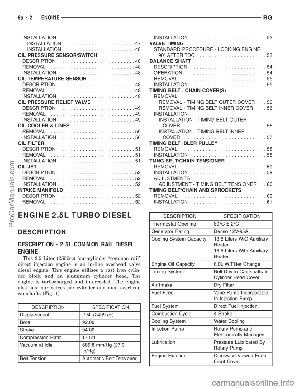
ENGINE 2.5L TURBO DIESEL
DESCRIPTION
DESCRIPTION - 2.5L COMMON RAIL DIESEL
ENGINE
This 2.5 Liter (2500cc) four-cylinder ªcommon railº
direct injection engine is an in-line overhead valve
diesel engine. This engine utilizes a cast iron cylin-
der block and an aluminum cylinder head. The
engine is turbocharged and intercooled. The engine
also has four valves per cylinder and dual overhead
camshafts (Fig. 1).
DESCRIPTION SPECIFICATION
Displacement 2.5L (2499 cc)
Bore 92.00
Stroke 94.00
Compression Ratio 17.5:1
Vacuum at Idle 685.8 mm/Hg (27.0
In/Hg)
Belt Tension Automatic Belt Tensioner
DESCRIPTION SPECIFICATION
Thermostat Opening 80ÉC 2ÉC
Generator Rating Denso 12V-95A
Cooling System Capacity 13.8 Liters W/O Auxiliary
Heater
16.6 Liters With Auxiliary
Heater
Engine Oil Capacity 6.0L W/Filter Change
Timing System Belt Driven Camshafts In
Cylinder Head Cover
Air Intake Dry Filter
Fuel Feed Vane Pump Incorporated
In Injection Pump
Fuel System Direct Fuel Injection
Combustion Cycle 4 Stroke
Cooling System Water Cooling
Injection Pump Rotary Pump and
Electronically Managed
Lubrication Pressure Lubricated By
Rotary Pump
Engine Rotation Clockwise Viewed From
Front Cover
9a - 2 ENGINERG
ProCarManuals.com
Page 1369 of 2399
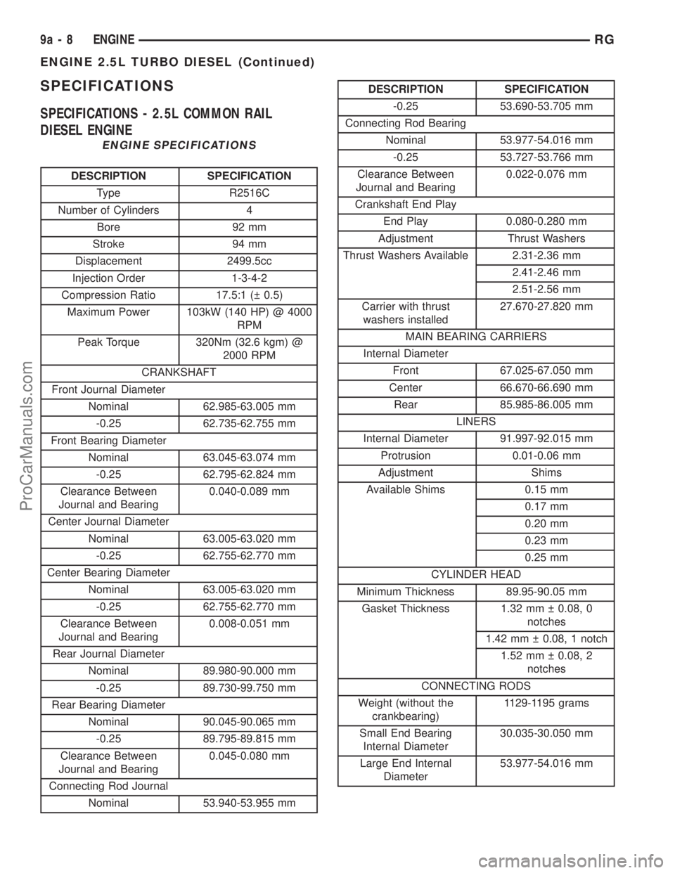
SPECIFICATIONS
SPECIFICATIONS - 2.5L COMMON RAIL
DIESEL ENGINE
ENGINE SPECIFICATIONS
DESCRIPTION SPECIFICATION
Type R2516C
Number of Cylinders 4
Bore 92 mm
Stroke 94 mm
Displacement 2499.5cc
Injection Order 1-3-4-2
Compression Ratio 17.5:1 ( 0.5)
Maximum Power 103kW (140 HP) @ 4000
RPM
Peak Torque 320Nm (32.6 kgm) @
2000 RPM
CRANKSHAFT
Front Journal Diameter
Nominal 62.985-63.005 mm
-0.25 62.735-62.755 mm
Front Bearing Diameter
Nominal 63.045-63.074 mm
-0.25 62.795-62.824 mm
Clearance Between
Journal and Bearing0.040-0.089 mm
Center Journal Diameter
Nominal 63.005-63.020 mm
-0.25 62.755-62.770 mm
Center Bearing Diameter
Nominal 63.005-63.020 mm
-0.25 62.755-62.770 mm
Clearance Between
Journal and Bearing0.008-0.051 mm
Rear Journal Diameter
Nominal 89.980-90.000 mm
-0.25 89.730-99.750 mm
Rear Bearing Diameter
Nominal 90.045-90.065 mm
-0.25 89.795-89.815 mm
Clearance Between
Journal and Bearing0.045-0.080 mm
Connecting Rod Journal
Nominal 53.940-53.955 mm
DESCRIPTION SPECIFICATION
-0.25 53.690-53.705 mm
Connecting Rod Bearing
Nominal 53.977-54.016 mm
-0.25 53.727-53.766 mm
Clearance Between
Journal and Bearing0.022-0.076 mm
Crankshaft End Play
End Play 0.080-0.280 mm
Adjustment Thrust Washers
Thrust Washers Available 2.31-2.36 mm
2.41-2.46 mm
2.51-2.56 mm
Carrier with thrust
washers installed27.670-27.820 mm
MAIN BEARING CARRIERS
Internal Diameter
Front 67.025-67.050 mm
Center 66.670-66.690 mm
Rear 85.985-86.005 mm
LINERS
Internal Diameter 91.997-92.015 mm
Protrusion 0.01-0.06 mm
Adjustment Shims
Available Shims 0.15 mm
0.17 mm
0.20 mm
0.23 mm
0.25 mm
CYLINDER HEAD
Minimum Thickness 89.95-90.05 mm
Gasket Thickness 1.32 mm 0.08, 0
notches
1.42 mm 0.08, 1 notch
1.52 mm 0.08, 2
notches
CONNECTING RODS
Weight (without the
crankbearing)1129-1195 grams
Small End Bearing
Internal Diameter30.035-30.050 mm
Large End Internal
Diameter53.977-54.016 mm
9a - 8 ENGINERG
ENGINE 2.5L TURBO DIESEL (Continued)
ProCarManuals.com
Page 1401 of 2399
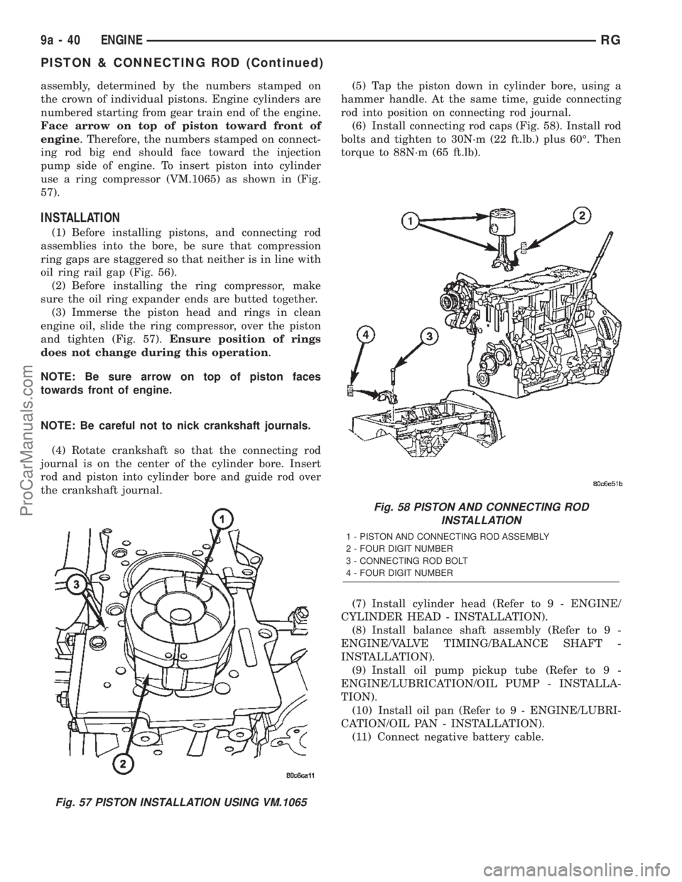
assembly, determined by the numbers stamped on
the crown of individual pistons. Engine cylinders are
numbered starting from gear train end of the engine.
Face arrow on top of piston toward front of
engine. Therefore, the numbers stamped on connect-
ing rod big end should face toward the injection
pump side of engine. To insert piston into cylinder
use a ring compressor (VM.1065) as shown in (Fig.
57).
INSTALLATION
(1) Before installing pistons, and connecting rod
assemblies into the bore, be sure that compression
ring gaps are staggered so that neither is in line with
oil ring rail gap (Fig. 56).
(2) Before installing the ring compressor, make
sure the oil ring expander ends are butted together.
(3) Immerse the piston head and rings in clean
engine oil, slide the ring compressor, over the piston
and tighten (Fig. 57).Ensure position of rings
does not change during this operation.
NOTE: Be sure arrow on top of piston faces
towards front of engine.
NOTE: Be careful not to nick crankshaft journals.
(4) Rotate crankshaft so that the connecting rod
journal is on the center of the cylinder bore. Insert
rod and piston into cylinder bore and guide rod over
the crankshaft journal.(5) Tap the piston down in cylinder bore, using a
hammer handle. At the same time, guide connecting
rod into position on connecting rod journal.
(6) Install connecting rod caps (Fig. 58). Install rod
bolts and tighten to 30N´m (22 ft.lb.) plus 60É. Then
torque to 88N´m (65 ft.lb).
(7) Install cylinder head (Refer to 9 - ENGINE/
CYLINDER HEAD - INSTALLATION).
(8) Install balance shaft assembly (Refer to 9 -
ENGINE/VALVE TIMING/BALANCE SHAFT -
INSTALLATION).
(9) Install oil pump pickup tube (Refer to 9 -
ENGINE/LUBRICATION/OIL PUMP - INSTALLA-
TION).
(10) Install oil pan (Refer to 9 - ENGINE/LUBRI-
CATION/OIL PAN - INSTALLATION).
(11) Connect negative battery cable.
Fig. 57 PISTON INSTALLATION USING VM.1065
Fig. 58 PISTON AND CONNECTING ROD
INSTALLATION
1 - PISTON AND CONNECTING ROD ASSEMBLY
2 - FOUR DIGIT NUMBER
3 - CONNECTING ROD BOLT
4 - FOUR DIGIT NUMBER
9a - 40 ENGINERG
PISTON & CONNECTING ROD (Continued)
ProCarManuals.com
Page 1435 of 2399
TURBOCHARGER SYSTEM
DESCRIPTION
CAUTION: The turbocharger is a performance part
and must not be tampered with. The wastegate
bracket is an integral part of the turbocharger. Tam-
pering with the wastegate components can reduce
durability by increasing cylinder pressure and ther-
mal loading due to incorrect inlet and exhaust man-
ifold pressure. Poor fuel economy and failure to
meet regulatory emissions laws may result. Increas-
ing the turbocharger boost WILL NOT increase
engine power.
The turbocharger is an exhaust-driven super-
charger which increases the pressure and density of
the air entering the engine. With the increase of air
entering the engine, more fuel can be injected into
the cylinders, which creates more power during com-
bustion.
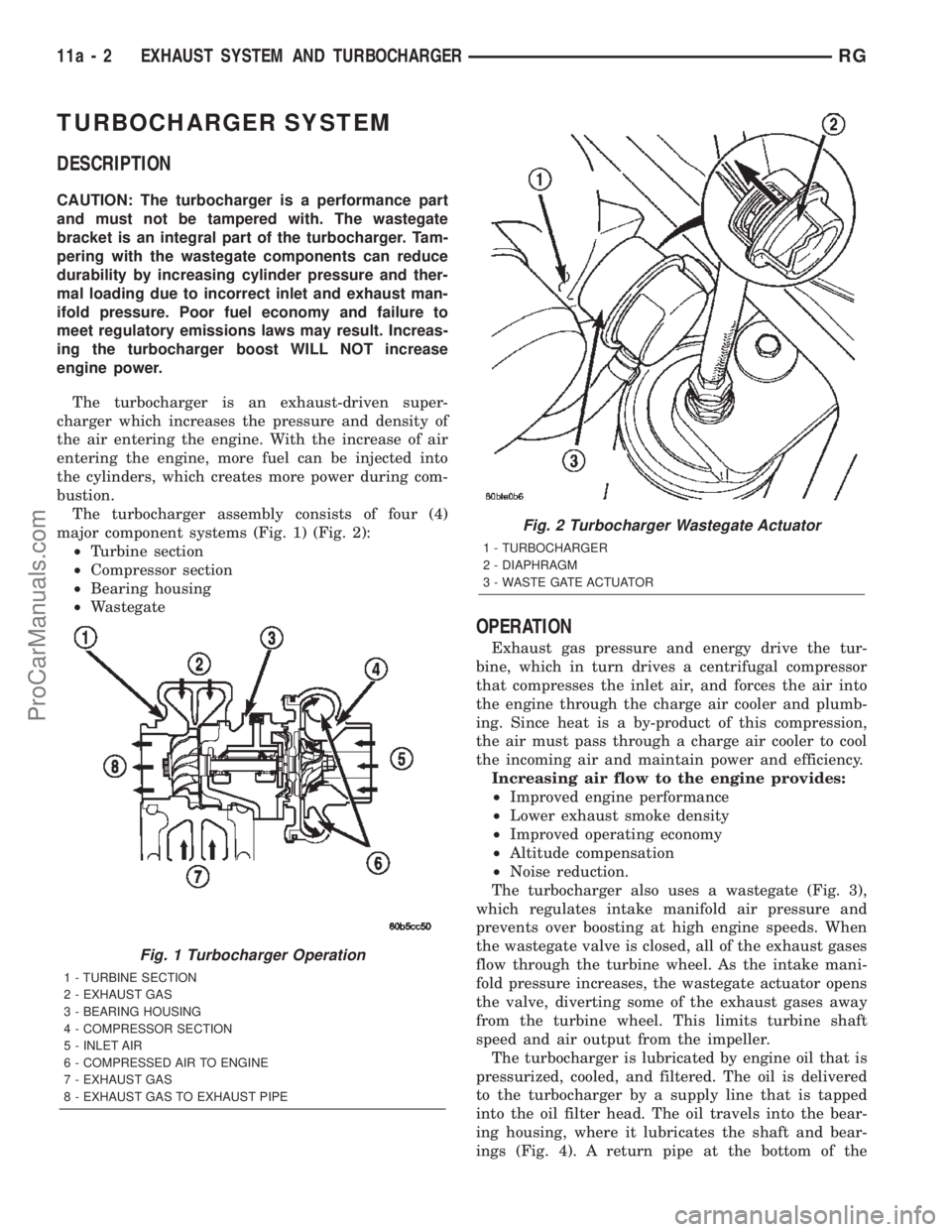
The turbocharger assembly consists of four (4)
major component systems (Fig. 1) (Fig. 2):
²Turbine section
²Compressor section
²Bearing housing
²Wastegate
OPERATION
Exhaust gas pressure and energy drive the tur-
bine, which in turn drives a centrifugal compressor
that compresses the inlet air, and forces the air into
the engine through the charge air cooler and plumb-
ing. Since heat is a by-product of this compression,
the air must pass through a charge air cooler to cool
the incoming air and maintain power and efficiency.
Increasing air flow to the engine provides:
²Improved engine performance
²Lower exhaust smoke density
²Improved operating economy
²Altitude compensation
²Noise reduction.
The turbocharger also uses a wastegate (Fig. 3),
which regulates intake manifold air pressure and
prevents over boosting at high engine speeds. When
the wastegate valve is closed, all of the exhaust gases
flow through the turbine wheel. As the intake mani-
fold pressure increases, the wastegate actuator opens
the valve, diverting some of the exhaust gases away
from the turbine wheel. This limits turbine shaft
speed and air output from the impeller.
The turbocharger is lubricated by engine oil that is
pressurized, cooled, and filtered. The oil is delivered
to the turbocharger by a supply line that is tapped
into the oil filter head. The oil travels into the bear-
ing housing, where it lubricates the shaft and bear-
ings (Fig. 4). A return pipe at the bottom of the
Fig. 1 Turbocharger Operation
1 - TURBINE SECTION
2 - EXHAUST GAS
3 - BEARING HOUSING
4 - COMPRESSOR SECTION
5 - INLET AIR
6 - COMPRESSED AIR TO ENGINE
7 - EXHAUST GAS
8 - EXHAUST GAS TO EXHAUST PIPE
Fig. 2 Turbocharger Wastegate Actuator
1 - TURBOCHARGER
2 - DIAPHRAGM
3 - WASTE GATE ACTUATOR
11a - 2 EXHAUST SYSTEM AND TURBOCHARGERRG
ProCarManuals.com
Page 2364 of 2399
is enabled to run another test during that trip. When
the test fails 6 times, the counter increments to 3, a
malfunction is entered, and a Freeze Frame is stored,
the code is matured and the MIL is illuminated. If
the first test passes, no further testing is conducted
during that trip.
The MIL is extinguished after three consecutive
good trips. The good trip criteria for the catalyst
monitor is more stringent than the failure criteria. In
order to pass the test and increment one good trip,
the downstream sensor switch rate must be less than
45% of the upstream rate. The failure percentages
are 59% respectively.
Enabling ConditionsÐThe following conditions
must typically be met before the PCM runs the cat-
alyst monitor. Specific times for each parameter may
be different from engine to engine.
²Accumulated drive time
²Enable time
²Ambient air temperature
²Barometric pressure
²Catalyst warm-up counter
²Engine coolant temperature
²Vehicle speed
²MAP
²RPM
²Engine in closed loop
²Fuel level
Pending ConditionsÐ
²Misfire DTC
²Front Oxygen Sensor Response
²Front Oxygen Sensor Heater Monitor
²Front Oxygen Sensor Electrical
²Rear Oxygen Sensor Rationality (middle check)
²Rear Oxygen Sensor Heater Monitor
²Rear Oxygen Sensor Electrical
²Fuel System Monitor
²All TPS faults
²All MAP faults
²All ECT sensor faults
²Purge flow solenoid functionality
²Purge flow solenoid electrical
²All PCM self test faults
²All CMP and CKP sensor faults
²All injector and ignition electrical faults
²Idle Air Control (IAC) motor functionality
²Vehicle Speed Sensor
²Brake switch (auto trans only)
²Intake air temperature
ConflictÐThe catalyst monitor does not run if any
of the following are conditions are present:
²EGR Monitor in progress (if equipped)
²Fuel system rich intrusive test in progress
²EVAP Monitor in progress
²Time since start is less than 60 seconds
²Low fuel level-less than 15 %²Low ambient air temperature
²Ethanel content learn is takeng place and the
ethenal used once flag is set
SuspendÐThe Task Manager does not mature a
catalyst fault if any of the following are present:
²Oxygen Sensor Monitor, Priority 1
²Oxygen Sensor Heater, Priority 1
²EGR Monitor, Priority 1 (if equipped)
²EVAP Monitor, Priority 1
²Fuel System Monitor, Priority 2
²Misfire Monitor, Priority 2
OPERATION - NON-MONITORED CIRCUITS
The PCM does not monitor all circuits, systems
and conditions that could have malfunctions causing
driveability problems. However, problems with these
systems may cause the PCM to store diagnostic trou-
ble codes for other systems or components. For exam-
ple, a fuel pressure problem will not register a fault
directly, but could cause a rich/lean condition or mis-
fire. This could cause the PCM to store an oxygen
sensor or misfire diagnostic trouble code.
The major non-monitored circuits are listed below
along with examples of failures modes that do not
directly cause the PCM to set a DTC, but for a sys-
tem that is monitored.
FUEL PRESSURE
The fuel pressure regulator controls fuel system
pressure. The PCM cannot detect a clogged fuel
pump inlet filter, clogged in-line fuel filter, or a
pinched fuel supply or return line. However, these
could result in a rich or lean condition causing the
PCM to store an oxygen sensor, fuel system, or mis-
fire diagnostic trouble code.
SECONDARY IGNITION CIRCUIT
The PCM cannot detect an inoperative ignition coil,
fouled or worn spark plugs, ignition cross firing, or
open spark plug cables. The misfire will however,
increase the oxygen content in the exhaust, deceiving
the PCM in to thinking the fuel system is too lean.
Also misfire detection.
CYLINDER COMPRESSION
The PCM cannot detect uneven, low, or high engine
cylinder compression. Low compression lowers O2
content in the exhaust. Leading to fuel system, oxy-
gen sensor, or misfire detection fault.
EXHAUST SYSTEM
The PCM cannot detect a plugged, restricted or
leaking exhaust system. It may set a EGR (if
equipped) or Fuel system or O2S fault.
RSEMISSIONS CONTROL25-5
EMISSIONS CONTROL (Continued)
ProCarManuals.com