2002 CHRYSLER CARAVAN ignition
[x] Cancel search: ignitionPage 1811 of 2399
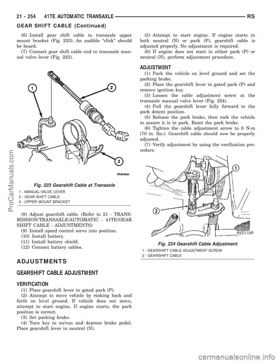
(6) Install gear shift cable to transaxle upper
mount bracket (Fig. 223). An audible ªclickº should
be heard.
(7) Connect gear shift cable end to transaxle man-
ual valve lever (Fig. 223).
(8) Adjust gearshift cable. (Refer to 21 - TRANS-
MISSION/TRANSAXLE/AUTOMATIC - 41TE/GEAR
SHIFT CABLE - ADJUSTMENTS)
(9) Install speed control servo into position.
(10) Install battery.
(11) Install battery shield.
(12) Connect battery cables.
ADJUSTMENTS
GEARSHIFT CABLE ADJUSTMENT
VERIFICATION
(1) Place gearshift lever in gated park (P).
(2) Attempt to move vehicle by rocking back and
forth on level ground. If vehicle does not move,
attempt to start engine. If engine starts, the park
position is correct.
(3) Set parking brake.
(4) Turn key to on/run and depress brake pedal.
Place gearshift lever in neutral (N).(5) Attempt to start engine. If engine starts in
both neutral (N) or park (P), gearshift cable is
adjusted properly. No adjustment is required.
(6) If engine does not start in either park (P) or
neutral (N), perform adjustment procedure.
ADJUSTMENT
(1) Park the vehicle on level ground and set the
parking brake.
(2) Place the gearshift lever in gated park (P) and
remove ignition key.
(3) Loosen the cable adjustment screw at the
transaxle manual valve lever (Fig. 224).
(4) Pull the gearshift lever fully forward to the
park detent position.
(5) Release the park brake, then rock the vehicle
to assure it is in park. Reset the park brake.
(6) Tighten the cable adjustment screw to 8 N´m
(70 in. lbs.). Gearshift cable should now be properly
adjusted.
(7) Verify adjustment by using the verification pro-
cedure.
Fig. 223 Gearshift Cable at Transaxle
1 - MANUAL VALVE LEVER
2 - GEAR SHIFT CABLE
3 - UPPER MOUNT BRACKET
Fig. 224 Gearshift Cable Adjustment
1 - GEARSHIFT CABLE ADJUSTMENT SCREW
2 - GEARSHIFT CABLE
21 - 254 41TE AUTOMATIC TRANSAXLERS
GEAR SHIFT CABLE (Continued)
ProCarManuals.com
Page 1833 of 2399
OPERATION
The Brake/Transmission Shift Interlock (BTSI)
Solenoid prevents the transmission shift lever from
being moved out of PARK (P) unless the brake pedal
is applied. The BTSI solenoid is hardwired to and
controlled by the Intelligent Power Module (IPM).
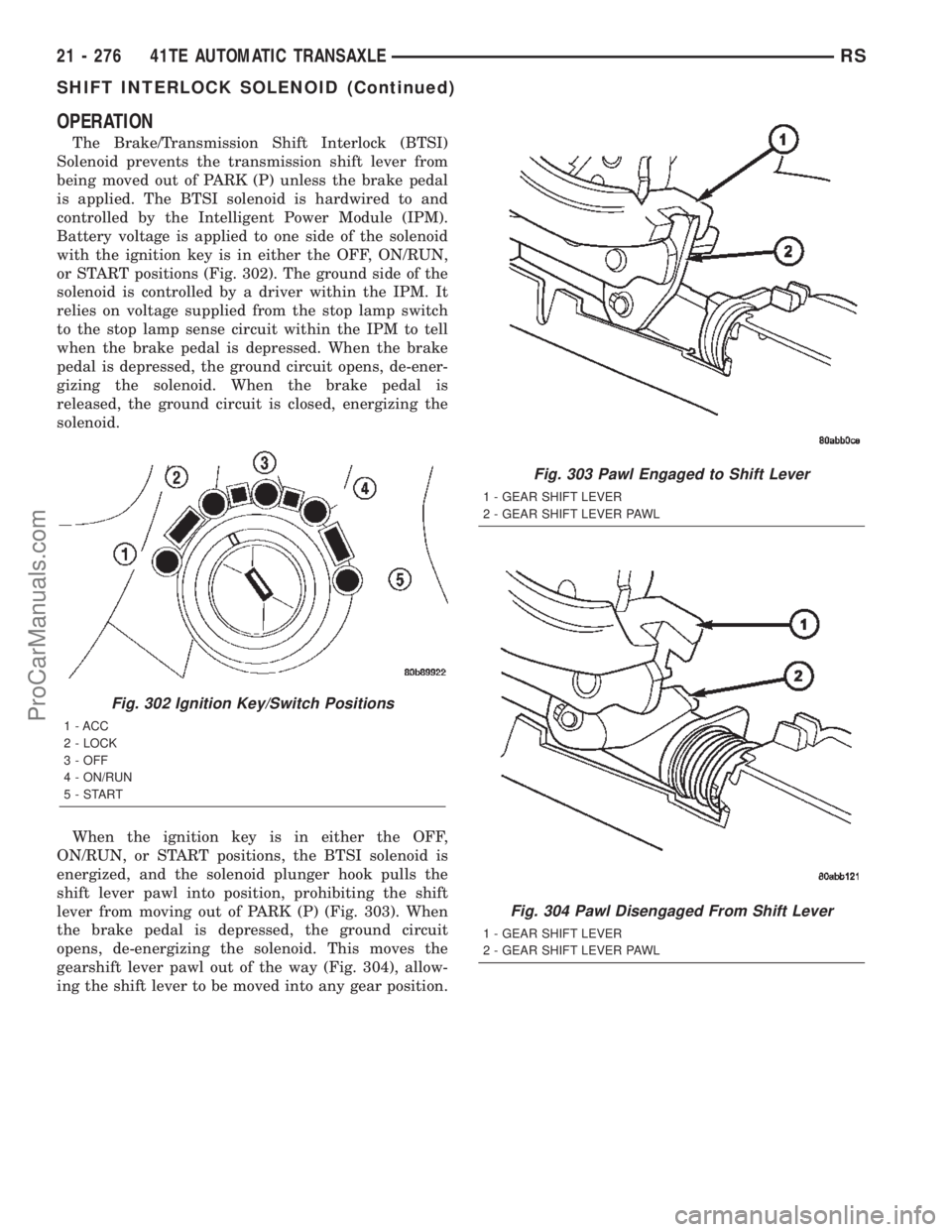
Battery voltage is applied to one side of the solenoid
with the ignition key is in either the OFF, ON/RUN,
or START positions (Fig. 302). The ground side of the
solenoid is controlled by a driver within the IPM. It
relies on voltage supplied from the stop lamp switch
to the stop lamp sense circuit within the IPM to tell
when the brake pedal is depressed. When the brake
pedal is depressed, the ground circuit opens, de-ener-
gizing the solenoid. When the brake pedal is
released, the ground circuit is closed, energizing the
solenoid.
When the ignition key is in either the OFF,
ON/RUN, or START positions, the BTSI solenoid is
energized, and the solenoid plunger hook pulls the
shift lever pawl into position, prohibiting the shift
lever from moving out of PARK (P) (Fig. 303). When
the brake pedal is depressed, the ground circuit
opens, de-energizing the solenoid. This moves the
gearshift lever pawl out of the way (Fig. 304), allow-
ing the shift lever to be moved into any gear position.
Fig. 302 Ignition Key/Switch Positions
1 - ACC
2 - LOCK
3 - OFF
4 - ON/RUN
5-START
Fig. 303 Pawl Engaged to Shift Lever
1 - GEAR SHIFT LEVER
2 - GEAR SHIFT LEVER PAWL
Fig. 304 Pawl Disengaged From Shift Lever
1 - GEAR SHIFT LEVER
2 - GEAR SHIFT LEVER PAWL
21 - 276 41TE AUTOMATIC TRANSAXLERS
SHIFT INTERLOCK SOLENOID (Continued)
ProCarManuals.com
Page 1834 of 2399
A conventional mechanical interlock system is also
used. This system manually prohibits shifter move-
ment when the ignition switch is in the LOCK or
ACC positions. Solenoid operation is not required in
these key positions.
For intended BTSI system operation, refer to the
following chart:
ACTION EXPECTED RESPONSE
1. Turn key to the9OFF9
position.1. Shifter CAN be shifted
out of park with brake
pedal applied.
2. Turn key to the
9ON/RUN9position.2. Shifter CANNOT be
shifted out of park.
3. Turn key to the
9ON/RUN9position and
depress the brake pedal.3. Shifter CAN be shifted
out of park.
4. Leave shifter in any
gear and try to return key
to the9LOCK9or9ACC9
position.4. Key cannot be
returned to the9LOCK9or
9ACC9position.
5. Return shifter to
9PARK9and try to remove
the key.5. Key can be removed
(after returning to9LOCK9
position).
6. With the key removed,
try to shift out of9PARK9.6. Shifter cannot be
shifted out of9PARK9.
NOTE: Any failure to meet these expected
responses requires system adjustment or repair.
DIAGNOSIS AND TESTING - BRAKE/
TRANSMISSION SHIFT INTERLOCK SOLENOID
For intended BTSI system operation, refer to the
following chart:
ACTION EXPECTED RESPONSE
1. Turn key to the9OFF9
position.1. Shifter CAN be shifted
out of park with brake
pedal applied.
2. Turn key to the
9ON/RUN9position.2. Shifter CANNOT be
shifted out of park.
3. Turn key to the
9ON/RUN9position and
depress the brake pedal.3. Shifter CAN be shifted
out of park.
4. Leave shifter in any
gear and try to return key
to the9LOCK9or9ACC9
position.4. Key cannot be
returned to the9LOCK9or
9ACC9position.
5. Return shifter to
9PARK9and try to remove
the key.5. Key can be removed
(after returning to9LOCK9
position).
ACTION EXPECTED RESPONSE
6. With the key removed,
try to shift out of9PARK9.6. Shifter cannot be
shifted out of9PARK9.
NOTE: Any failure to meet these expected
responses requires system repair. Refer to the
appropriate Diagnostic Information.
REMOVAL
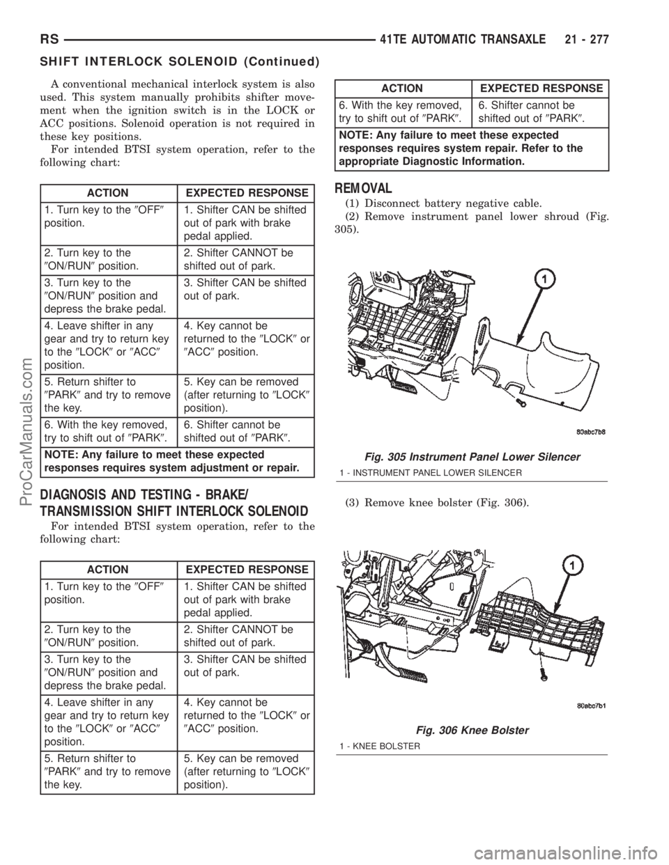
(1) Disconnect battery negative cable.
(2) Remove instrument panel lower shroud (Fig.
305).
(3) Remove knee bolster (Fig. 306).
Fig. 305 Instrument Panel Lower Silencer
1 - INSTRUMENT PANEL LOWER SILENCER
Fig. 306 Knee Bolster
1 - KNEE BOLSTER
RS41TE AUTOMATIC TRANSAXLE21 - 277
SHIFT INTERLOCK SOLENOID (Continued)
ProCarManuals.com
Page 1848 of 2399
TRANSMISSION CONTROL
RELAY
DESCRIPTION
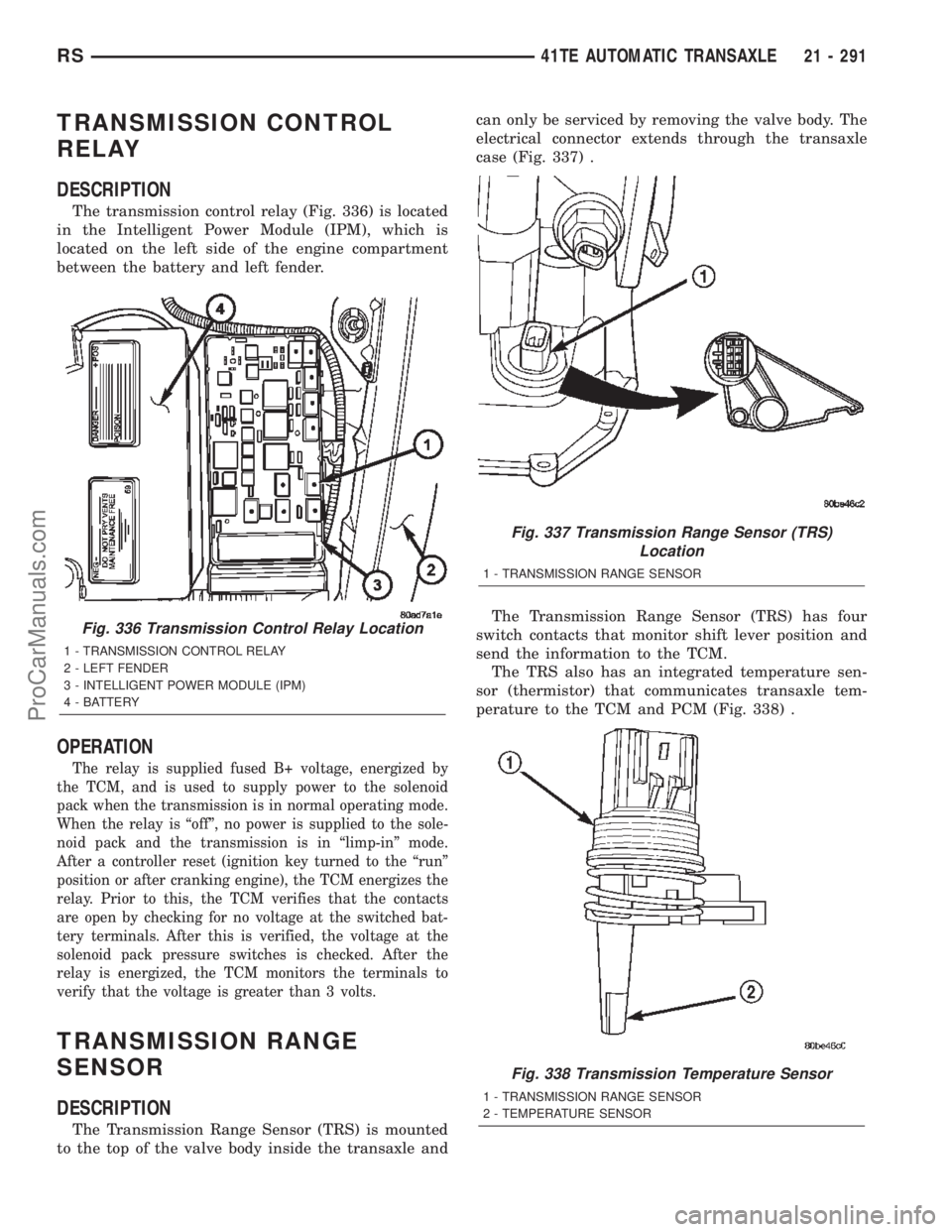
The transmission control relay (Fig. 336) is located
in the Intelligent Power Module (IPM), which is
located on the left side of the engine compartment
between the battery and left fender.
OPERATION
The relay is supplied fused B+ voltage, energized by
the TCM, and is used to supply power to the solenoid
pack when the transmission is in normal operating mode.
When the relay is ªoffº, no power is supplied to the sole-
noid pack and the transmission is in ªlimp-inº mode.
After a controller reset (ignition key turned to the ªrunº
position or after cranking engine), the TCM energizes the
relay. Prior to this, the TCM verifies that the contacts
are open by checking for no voltage at the switched bat-
tery terminals. After this is verified, the voltage at the
solenoid pack pressure switches is checked. After the
relay is energized, the TCM monitors the terminals to
verify that the voltage is greater than 3 volts.
TRANSMISSION RANGE
SENSOR
DESCRIPTION
The Transmission Range Sensor (TRS) is mounted
to the top of the valve body inside the transaxle andcan only be serviced by removing the valve body. The
electrical connector extends through the transaxle
case (Fig. 337) .
The Transmission Range Sensor (TRS) has four
switch contacts that monitor shift lever position and
send the information to the TCM.
The TRS also has an integrated temperature sen-
sor (thermistor) that communicates transaxle tem-
perature to the TCM and PCM (Fig. 338) .
Fig. 336 Transmission Control Relay Location
1 - TRANSMISSION CONTROL RELAY
2 - LEFT FENDER
3 - INTELLIGENT POWER MODULE (IPM)
4 - BATTERY
Fig. 337 Transmission Range Sensor (TRS)
Location
1 - TRANSMISSION RANGE SENSOR
Fig. 338 Transmission Temperature Sensor
1 - TRANSMISSION RANGE SENSOR
2 - TEMPERATURE SENSOR
RS41TE AUTOMATIC TRANSAXLE21 - 291
ProCarManuals.com
Page 1850 of 2399
is requested when the TCM pulses this signal to
ground. The PCM recognizes this request and
responds by retarding ignition timing, killing fuel
injectors, etc. The PCM sends a confirmation of the
request to the TCM via the communication bus.
Torque reduction is not noticable by the driver, and
usually lasts for a very short period of time.
If the confirmation signal is not received by the
TCM after two sequential request messages, a diag-
nostic trouble code will be set.
VALVE BODY
DESCRIPTION
The valve body assembly consists of a cast alumi-
num valve body, a separator plate, and transfer
plate. The valve body contains valves and check balls
that control fluid delivery to the torque converter
clutch, solenoid/pressure switch assembly, and fric-
tional clutches. The valve body contains the following
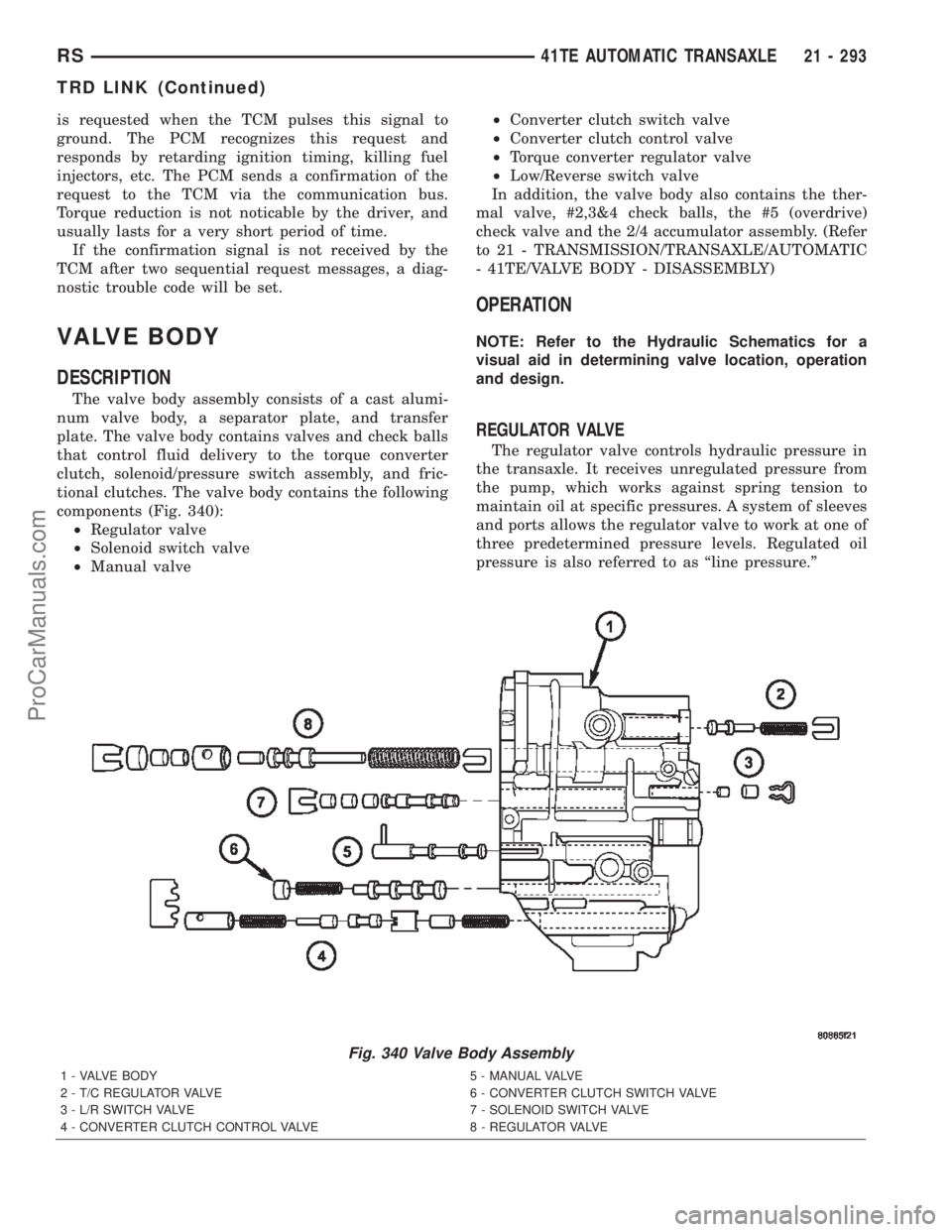
components (Fig. 340):
²Regulator valve
²Solenoid switch valve
²Manual valve²Converter clutch switch valve
²Converter clutch control valve
²Torque converter regulator valve
²Low/Reverse switch valve
In addition, the valve body also contains the ther-
mal valve, #2,3&4 check balls, the #5 (overdrive)
check valve and the 2/4 accumulator assembly. (Refer
to 21 - TRANSMISSION/TRANSAXLE/AUTOMATIC
- 41TE/VALVE BODY - DISASSEMBLY)
OPERATION
NOTE: Refer to the Hydraulic Schematics for a
visual aid in determining valve location, operation
and design.
REGULATOR VALVE
The regulator valve controls hydraulic pressure in
the transaxle. It receives unregulated pressure from
the pump, which works against spring tension to
maintain oil at specific pressures. A system of sleeves
and ports allows the regulator valve to work at one of
three predetermined pressure levels. Regulated oil
pressure is also referred to as ªline pressure.º
Fig. 340 Valve Body Assembly
1 - VALVE BODY 5 - MANUAL VALVE
2 - T/C REGULATOR VALVE 6 - CONVERTER CLUTCH SWITCH VALVE
3 - L/R SWITCH VALVE 7 - SOLENOID SWITCH VALVE
4 - CONVERTER CLUTCH CONTROL VALVE 8 - REGULATOR VALVE
RS41TE AUTOMATIC TRANSAXLE21 - 293
TRD LINK (Continued)
ProCarManuals.com
Page 1970 of 2399
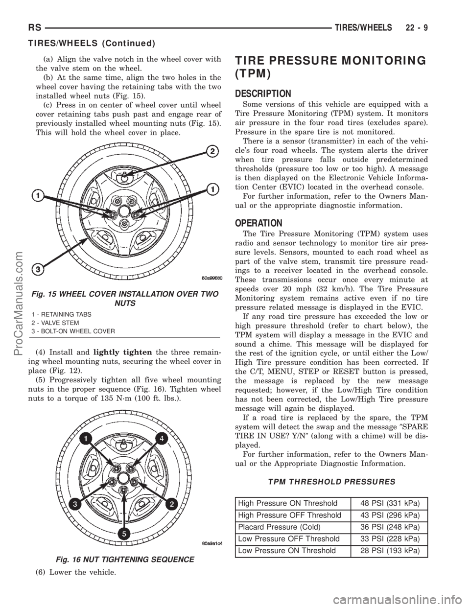
(a) Align the valve notch in the wheel cover with
the valve stem on the wheel.
(b) At the same time, align the two holes in the
wheel cover having the retaining tabs with the two
installed wheel nuts (Fig. 15).
(c) Press in on center of wheel cover until wheel
cover retaining tabs push past and engage rear of
previously installed wheel mounting nuts (Fig. 15).
This will hold the wheel cover in place.
(4) Install andlightly tightenthe three remain-
ing wheel mounting nuts, securing the wheel cover in
place (Fig. 12).
(5) Progressively tighten all five wheel mounting
nuts in the proper sequence (Fig. 16). Tighten wheel
nuts to a torque of 135 N´m (100 ft. lbs.).
(6) Lower the vehicle.TIRE PRESSURE MONITORING
(TPM)
DESCRIPTION
Some versions of this vehicle are equipped with a
Tire Pressure Monitoring (TPM) system. It monitors
air pressure in the four road tires (excludes spare).
Pressure in the spare tire is not monitored.
There is a sensor (transmitter) in each of the vehi-
cle's four road wheels. The system alerts the driver
when tire pressure falls outside predetermined
thresholds (pressure too low or too high). A message
is then displayed on the Electronic Vehicle Informa-
tion Center (EVIC) located in the overhead console.
For further information, refer to the Owners Man-
ual or the appropriate diagnostic information.
OPERATION
The Tire Pressure Monitoring (TPM) system uses
radio and sensor technology to monitor tire air pres-
sure levels. Sensors, mounted to each road wheel as
part of the valve stem, transmit tire pressure read-
ings to a receiver located in the overhead console.
These transmissions occur once every minute at
speeds over 20 mph (32 km/h). The Tire Pressure
Monitoring system remains active even if no tire
pressure related message is displayed in the EVIC.
If any road tire pressure has exceeded the low or
high pressure threshold (refer to chart below), the
TPM system will display a message in the EVIC and
sound a chime. This message will be displayed for
the rest of the ignition cycle, or until either the Low/
High Tire pressure condition has been corrected. If
the C/T, MENU, STEP or RESET button is pressed,
the message is replaced by the new message
requested; however, if the Low/High Tire condition
has not been corrected, the Low/High Tire pressure
message will again be displayed.
If a road tire is replaced by the spare, the TPM
system will detect the swap and the message9SPARE
TIRE IN USE? Y/N9(along with a chime) will be dis-
played.
For further information, refer to the Owners Man-
ual or the Appropriate Diagnostic Information.
TPM THRESHOLD PRESSURES
High Pressure ON Threshold 48 PSI (331 kPa)
High Pressure OFF Threshold 43 PSI (296 kPa)
Placard Pressure (Cold) 36 PSI (248 kPa)
Low Pressure OFF Threshold 33 PSI (228 kPa)
Low Pressure ON Threshold 28 PSI (193 kPa)
Fig. 15 WHEEL COVER INSTALLATION OVER TWO
NUTS
1 - RETAINING TABS
2 - VALVE STEM
3 - BOLT-ON WHEEL COVER
Fig. 16 NUT TIGHTENING SEQUENCE
RSTIRES/WHEELS22-9
TIRES/WHEELS (Continued)
ProCarManuals.com
Page 1984 of 2399
BODY
TABLE OF CONTENTS
page page
BODY
DESCRIPTION - VEHICLE IDENTIFICATION....1
WARNING
SAFETY PRECAUTIONS AND WARNINGS . . . 1
DIAGNOSIS AND TESTING
DIAGNOSIS AND TESTING - WATER LEAKS . 1
DIAGNOSIS AND TESTING - WIND NOISE . . . 2
STANDARD PROCEDURE
STANDARD PROCEDURE - PLASTIC BODY
PANEL REPAIR........................3
STANDARD PROCEDURE - HEAT STAKING . 10
SPECIFICATIONS
TORQUE............................11
BODY LUBRICATION...................12SPECIAL TOOLS
BODY..............................13
DOOR - FRONT.........................14
DOORS - SLIDING.......................24
DECKLID/HATCH/LIFTGATE/TAILGATE.......39
EXTERIOR.............................44
HOOD.................................60
INSTRUMENT PANEL.....................63
INTERIOR..............................72
PAINT.................................83
SEATS................................85
STATIONARY GLASS....................107
WEATHERSTRIP/SEALS..................112
BODY STRUCTURE.....................115
BODY
DESCRIPTION - VEHICLE IDENTIFICATION
Throughout this group, references to the
DaimlerChrysler Corporation vehicle family identifi-
cation code are used when describing a procedure
that is unique to that vehicle. Refer to Introduction
Group of this manual for detailed information on
vehicle identification. If a procedure is common to all
vehicles covered in this manual, no reference will be
made to a vehicle family code.
WARNING
SAFETY PRECAUTIONS AND WARNINGS
WARNING: USE A OSHA APPROVED BREATHING
FILTER WHEN SPRAYING PAINT OR SOLVENTS IN
A CONFINED AREA. PERSONAL INJURY CAN
RESULT.
AVOID PROLONGED SKIN CONTACT WITH PETRO-
LEUM OR ALCOHOL ± BASED CLEANING SOL-
VENTS. PERSONAL INJURY CAN RESULT.
DO NOT STAND UNDER A HOISTED VEHICLE THAT
IS NOT PROPERLY SUPPORTED ON SAFETY
STANDS. PERSONAL INJURY CAN RESULT.
CAUTION: When holes must be drilled or punched
in an inner body panel, verify depth of space to the
outer body panel, electrical wiring, or other compo-
nents. Damage to vehicle can result.
Do not weld exterior panels unless combustiblematerial on the interior of vehicle is removed from
the repair area. Fire or hazardous conditions, can
result.
Always have a fire extinguisher ready for use when
welding.
Disconnect the negative (-) cable clamp from the
battery when servicing electrical components that
are live when the ignition is OFF. Damage to electri-
cal system can result.
Do not use abrasive chemicals or compounds on
painted surfaces. Damage to finish can result.
Do not use harsh alkaline based cleaning solvents
on painted or upholstered surfaces. Damage to fin-
ish or color can result.
Do not hammer or pound on plastic trim panel
when servicing interior trim. Plastic panels can
break.
DIAGNOSIS AND TESTING
DIAGNOSIS AND TESTING - WATER LEAKS
Water leaks can be caused by poor sealing,
improper body component alignment, body seam
porosity, missing plugs, or blocked drain holes. Cen-
trifugal and gravitational force can cause water to
drip from a location away from the actual leak point,
making leak detection difficult. All body sealing
points should be water tight in normal wet-driving
conditions. Water flowing downward from the front of
the vehicle should not enter the passenger or luggage
compartment. Moving sealing surfaces will not
always seal water tight under all conditions. At
times, side glass or door seals will allow water to
RSBODY23-1
ProCarManuals.com
Page 2246 of 2399
pressed, the set temp value will become 55 but the
display will show LO. If the set temp is 85 and the
up button is pressed, the set temp value will become
90 but the display will show HIGH. Temperatures
can be displayed in either metric or Fahrenheit,
which is controlled from the overhead console.
²A rocker switch that selects a cool-down rate.
LO-AUTO or HI-AUTO are displayed when the sys-
tem is in automatic operation.
²A defroster button which turns on the defroster
independently during full automatic control. A
defroster symbol illuminates in the display when the
button is pressed.
²Air recirculation button. A Recirculation symbol
appears in the display when the button is pressed, or
when the system exceeds 80 percent circulated air
under automatic control due to high air conditioning
demand.
²Rear window defogger on/off switch. A graphic
symbol shows when the defroster is on.
²An air conditioning button that allows the com-
pressor to be turned off. A Snowflake symbol is illu-
minated when air conditioning is on, whether under
manual or automatic control.
²Rotary knob for front fan speed selection can
override the automatic controls. LEDs surrounding
the knob show the current setting.
²Rotary knob for control of the Rear system.
²A rotary knob for mode control can override the
automatic controls. LEDs surrounding the knob show
the current setting.
²Computer logic remembers the settings of the
controls when the ignition is turned off and retains
those settings after a restart. If the system is off
when the ignition is turned off it will be off when the
engine is restarted, etc.
²Computer logic provides variable air recircula-
tion under high temperature and humidity condi-
tions. Because recirculation is generally accompanied
by increased fan noise, the proportion of recirculated
to outside air gradually approaches full recirculation
over a broad temperature range.
²A graphic symbol of the windshield that illumi-
nates when the windshield wiper deicer is active.
REAR CONTROL PANEL
A rear control panel centrally mounted on the
headliner includes a vacuum-flourescent digital dis-
play, a rocker control for temperature and rotary con-
trols for adjustment of mode and fan speed control of
the rear unit by intermediate seat passengers.
OPERATION
OPERATION - DUAL ZONE
²The mode control knob enables continously vari-
able proportioning of air flow between modes but has
detents adjacent to each icon.
²The blower control provides five separate speeds.
²When the fan is off, the HVAC computer closes
the recirculation door to prevent outside air from
entering the passenger compartment.
²Interior air may be recirculated to speed up
heating or cooling in all modes except defrost and
mix by pressing the Recirculate button on the control
panel.
²To reduce humidity for rapid defogging the A/C
compressor runs automatically in modes from ªmix'
to full defrost when outside temperatures are above
freezing.
²Air conditioning is available in any mode by
pressing the snowflake, A/C on/off, button.
OPERATION - MANUAL THREE ZONE
FRONT CONTROL PANEL
²Primary control of the rear compartment unit is
on the instrument panel. This control allows the
driver to set the rear compartment fan speed, to turn
the rear unit off, or to give control to the intermedi-
ate seat occupants by switching to the REAR posi-
tion. When the rear unit is controlled from the
instrument panel, rear air temperature is based on
the driver-side temperature control position, and the
mode (floor or overhead air) is based on the front
control's mode position.
²The mode control knob enables continously vari-
able proportioning of air flow between modes but has
detents adjacent to each icon.
²The blower control provides five separate speeds
and Off. When the fan is off, the HVAC computer
closes the recirculation door to prevent outside air
from entering the passenger compartment.
²Interior air may be recirculated to speed up
heating or cooling in all modes exccept defrost and
mix by pressing the Recirculate button on the control
panel.
²To reduce humidity for rapid defogging the A/C
compressor runs automatically in modes from ªmix'
to full defrost when outside temperatures are above
freezing.
²Air conditioning is available in any mode by
pressing the snowflake, A/C on/off, button.
RSHEATING & AIR CONDITIONING24-3
HEATING & AIR CONDITIONING (Continued)
ProCarManuals.com