2002 CHRYSLER CARAVAN ignition
[x] Cancel search: ignitionPage 1494 of 2399
CAUTION: The high-pressure fuel lines cannot con-
tact each other or other components. Do not
attempt to weld high-pressure fuel lines or to repair
lines that are damaged. Only use the recommended
lines when replacement of high-pressure fuel line is
necessary.
FUEL TRANSFER PUMP
DESCRIPTION
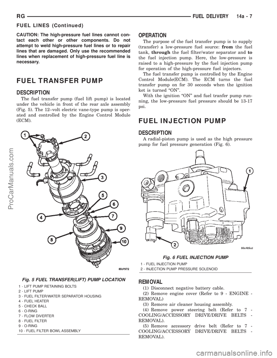
The fuel transfer pump (fuel lift pump) is located
under the vehicle in front of the rear axle assembly
(Fig. 5). The 12±volt electric vane-type pump is oper-
ated and controlled by the Engine Control Module
(ECM).
OPERATION
The purpose of the fuel transfer pump is to supply
(transfer) a low-pressure fuel source:fromthe fuel
tank,throughthe fuel filter/water separator andto
the fuel injection pump. Here, the low-pressure is
raised to a high-pressure by the fuel injection pump
for operation of the high-pressure fuel injectors.
The fuel transfer pump is controlled by the Engine
Control Module(ECM). The ECM turns the fuel
transfer pump on for 30 seconds when the ignition
ket is turned ªONº.
With the ignition ªONº and fuel tranfer pump run-
ning, the low-pressure fuel pressure should be 13-17
psi.
FUEL INJECTION PUMP
DESCRIPTION
A radial-piston pump is used as the high pressure
pump for fuel pressure generation (Fig. 6).
REMOVAL
(1) Disconnect negative battery cable.
(2) Remove engine cover (Refer to 9 - ENGINE -
REMOVAL)
(3) Remove air cleaner housing assembly.
(4) Remove power steering belt (Refer to 7 -
COOLING/ACCESSORY DRIVE/DRIVE BELTS -
REMOVAL).
(5) Remove accessory drive belt (Refer to 7 -
COOLING/ACCESSORY DRIVE/DRIVE BELTS -
REMOVAL).
Fig. 5 FUEL TRANSFER(LIFT) PUMP LOCATION
1 - LIFT PUMP RETAINING BOLTS
2 - LIFT PUMP
3 - FUEL FILTER/WATER SEPARATOR HOUSING
4 - FUEL HEATER
5 - CHECK BALL
6 - O-RING
7 - FLOW DIVERTER
8 - FUEL FILTER
9 - O-RING
10 - FUEL FILTER BOWL ASSEMBLY
Fig. 6 FUEL INJECTION PUMP
1 - FUEL INJECTION PUMP
2 - INJECTION PUMP PRESSURE SOLENOID
RGFUEL DELIVERY14a-7
FUEL LINES (Continued)
ProCarManuals.com
Page 1497 of 2399
(6) Using special tool VM.1055 (Fig. 7), torque
injection pump sprocket retaining nut to 88.3N´m.
(7) Connect fuel pressure solenoid electrical con-
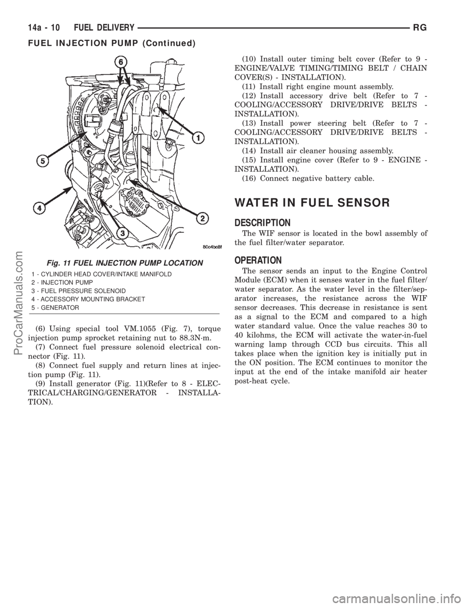
nector (Fig. 11).
(8) Connect fuel supply and return lines at injec-
tion pump (Fig. 11).
(9) Install generator (Fig. 11)(Refer to 8 - ELEC-
TRICAL/CHARGING/GENERATOR - INSTALLA-
TION).(10) Install outer timing belt cover (Refer to 9 -
ENGINE/VALVE TIMING/TIMING BELT / CHAIN
COVER(S) - INSTALLATION).
(11) Install right engine mount assembly.
(12) Install accessory drive belt (Refer to 7 -
COOLING/ACCESSORY DRIVE/DRIVE BELTS -
INSTALLATION).
(13) Install power steering belt (Refer to 7 -
COOLING/ACCESSORY DRIVE/DRIVE BELTS -
INSTALLATION).
(14) Install air cleaner housing assembly.
(15) Install engine cover (Refer to 9 - ENGINE -
INSTALLATION).
(16) Connect negative battery cable.
WATER IN FUEL SENSOR
DESCRIPTION
The WIF sensor is located in the bowl assembly of
the fuel filter/water separator.
OPERATION
The sensor sends an input to the Engine Control
Module (ECM) when it senses water in the fuel filter/
water separator. As the water level in the filter/sep-
arator increases, the resistance across the WIF
sensor decreases. This decrease in resistance is sent
as a signal to the ECM and compared to a high
water standard value. Once the value reaches 30 to
40 kilohms, the ECM will activate the water-in-fuel
warning lamp through CCD bus circuits. This all
takes place when the ignition key is initially put in
the ON position. The ECM continues to monitor the
input at the end of the intake manifold air heater
post-heat cycle.
Fig. 11 FUEL INJECTION PUMP LOCATION
1 - CYLINDER HEAD COVER/INTAKE MANIFOLD
2 - INJECTION PUMP
3 - FUEL PRESSURE SOLENOID
4 - ACCESSORY MOUNTING BRACKET
5 - GENERATOR
14a - 10 FUEL DELIVERYRG
FUEL INJECTION PUMP (Continued)
ProCarManuals.com
Page 1513 of 2399
COLUMN
TABLE OF CONTENTS
page page
COLUMN
DESCRIPTION - STEERING COLUMN.......10
WARNING
WARNINGS AND CAUTIONS.............10
DIAGNOSIS AND TESTING - STEERING
COLUMN............................12
REMOVAL.............................12
INSTALLATION.........................13
SPECIFICATIONS
COLUMN TORQUE....................14
IGNITION SWITCH
REMOVAL.............................15
INSTALLATION.........................16
LOCK CYLINDER HOUSING
DESCRIPTION - IGNITION INTERLOCK......17
REMOVAL.............................17INSTALLATION.........................20
KEY/LOCK CYLINDER
DESCRIPTION.........................21
OPERATION...........................21
REMOVAL.............................22
INSTALLATION.........................22
GEAR SHIFT LEVER
REMOVAL.............................22
INSTALLATION.........................22
SHROUD
REMOVAL.............................23
INSTALLATION.........................23
STEERING WHEEL
REMOVAL.............................23
INSTALLATION.........................25
COLUMN
DESCRIPTION - STEERING COLUMN
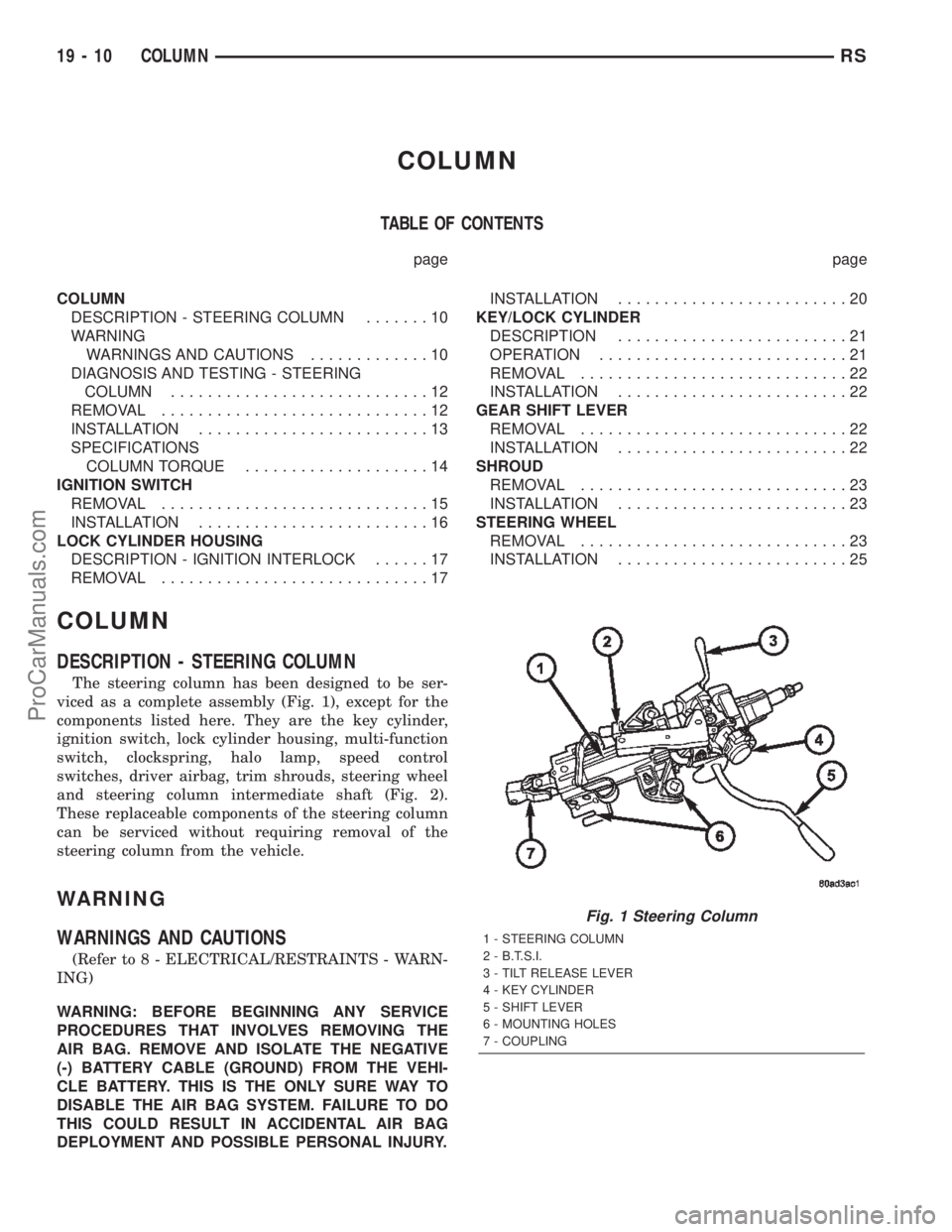
The steering column has been designed to be ser-
viced as a complete assembly (Fig. 1), except for the
components listed here. They are the key cylinder,
ignition switch, lock cylinder housing, multi-function
switch, clockspring, halo lamp, speed control
switches, driver airbag, trim shrouds, steering wheel
and steering column intermediate shaft (Fig. 2).
These replaceable components of the steering column
can be serviced without requiring removal of the
steering column from the vehicle.
WARNING
WARNINGS AND CAUTIONS
(Refer to 8 - ELECTRICAL/RESTRAINTS - WARN-
ING)
WARNING: BEFORE BEGINNING ANY SERVICE
PROCEDURES THAT INVOLVES REMOVING THE
AIR BAG. REMOVE AND ISOLATE THE NEGATIVE
(-) BATTERY CABLE (GROUND) FROM THE VEHI-
CLE BATTERY. THIS IS THE ONLY SURE WAY TO
DISABLE THE AIR BAG SYSTEM. FAILURE TO DO
THIS COULD RESULT IN ACCIDENTAL AIR BAG
DEPLOYMENT AND POSSIBLE PERSONAL INJURY.
Fig. 1 Steering Column
1 - STEERING COLUMN
2 - B.T.S.I.
3 - TILT RELEASE LEVER
4 - KEY CYLINDER
5 - SHIFT LEVER
6 - MOUNTING HOLES
7 - COUPLING
19 - 10 COLUMNRS
ProCarManuals.com
Page 1515 of 2399
WARNING: THE AIR BAG SYSTEM IS A SENSITIVE,
COMPLEX ELECTRO-MECHANICAL UNIT. BEFORE
ATTEMPTING TO DIAGNOSE, REMOVE OR INSTALL
THE AIR BAG SYSTEM COMPONENTS YOU MUST
FIRST DISCONNECT AND ISOLATE THE BATTERY
NEGATIVE (GROUND) CABLE. THEN WAIT TWO
MINUTES FOR THE SYSTEM CAPACITOR TO DIS-
CHARGE. FAILURE TO DO SO COULD RESULT IN
ACCIDENTAL DEPLOYMENT OF THE AIR BAG AND
POSSIBLE PERSONAL INJURY. THE FASTENERS,
SCREWS, AND BOLTS, ORIGINALLY USED FOR
THE AIR BAG COMPONENTS, HAVE SPECIAL
COATINGS AND ARE SPECIFICALLY DESIGNED
FOR THE AIR BAG SYSTEM. THEY MUST NEVER
BE REPLACED WITH ANY SUBSTITUTES. ANYTIME
A NEW FASTENER IS NEEDED, REPLACE WITH
THE CORRECT FASTENERS PROVIDED IN THE
SERVICE PACKAGE OR FASTENERS LISTED IN
THE PARTS BOOKS.
WARNING: SAFETY GOGGLES SHOULD BE WORN
AT ALL TIMES WHEN WORKING ON STEERING
COLUMNS.
CAUTION: Disconnect negative (ground) cable from
the battery before servicing any column compo-
nent.
CAUTION: Do not attempt to remove the pivot pins
to disassemble the tilting mechanism. Damage will
occur.
DIAGNOSIS AND TESTING - STEERING
COLUMN
For diagnosis of conditions relating to the steering
column (Refer to 19 - STEERING - DIAGNOSIS ANDTESTING) and (Refer to 19 - STEERING - DIAGNO-
SIS AND TESTING).
REMOVAL
NOTE: Before proceeding, (Refer to 19 - STEERING/
COLUMN - WARNING).
(1) Make sure the front wheels of the vehicle are
in the STRAIGHT AHEAD position before beginning
the column removal procedure.
(2) Disconnect negative (ground) cable from the
battery and isolate cable from battery terminal.
(3) Remove the lower shroud (Refer to 19 -
STEERING/COLUMN/LOWER SHROUD - REMOV-
AL).
(4) Remove the traction off switch.
(5) Remove the upper shroud.
(6) Remove the cluster trim bezel (Refer to 23 -
BODY/INSTRUMENT PANEL/CLUSTER BEZEL -
REMOVAL).
(7) Remove the knee blocker (Refer to 23 - BODY/
INSTRUMENT PANEL/STEERING COLUMN
OPENING COVER - REMOVAL).
(8) Remove the parking brake handle link.
(9) Remove the knee blocker reinforcement (Refer
to 23 - BODY/INSTRUMENT PANEL/KNEE
BLOCKER - REMOVAL).
(10) Remove the airbag (Refer to 8 - ELECTRI-
CAL/RESTRAINTS/DRIVER AIRBAG - REMOVAL).
(11) Remove the steering wheel retaining nut.
(12) Remove the vibration damper weight.
(13) Remove the steering wheel (Refer to 19 -
STEERING/COLUMN/STEERING WHEEL -
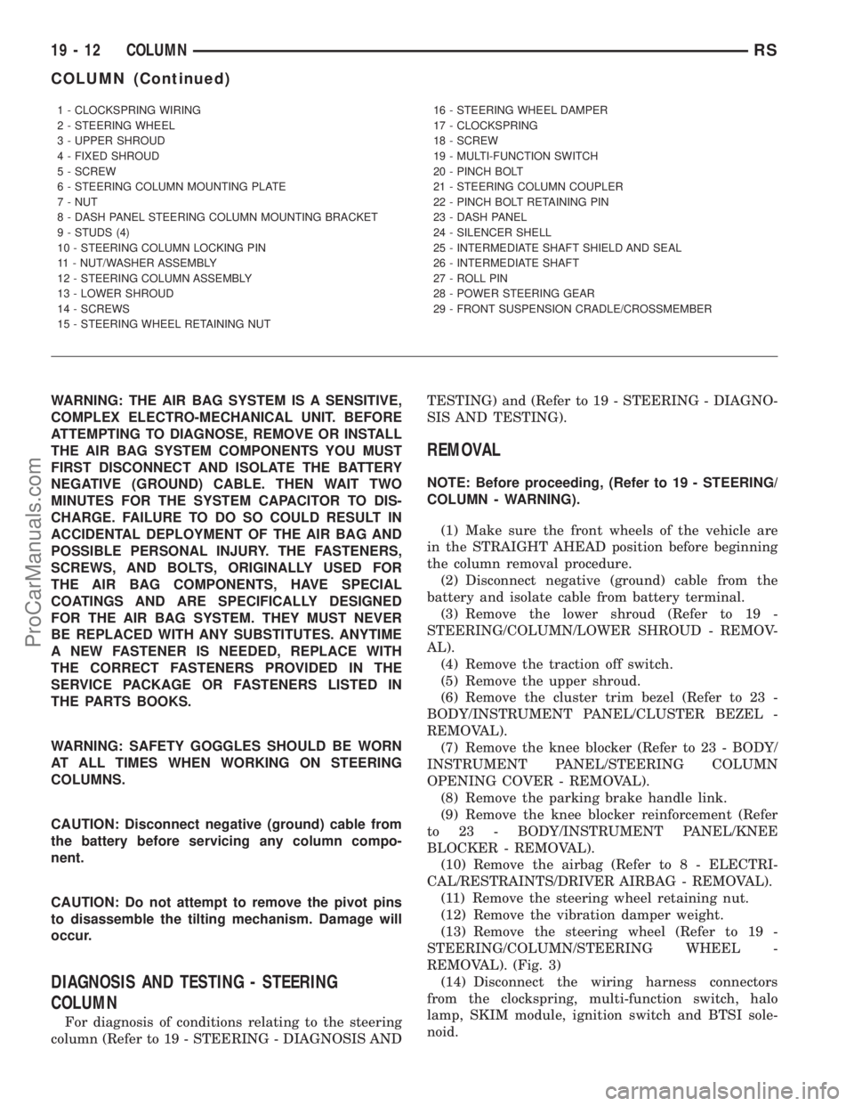
REMOVAL). (Fig. 3)
(14) Disconnect the wiring harness connectors
from the clockspring, multi-function switch, halo
lamp, SKIM module, ignition switch and BTSI sole-
noid.
1 - CLOCKSPRING WIRING
2 - STEERING WHEEL
3 - UPPER SHROUD
4 - FIXED SHROUD
5 - SCREW
6 - STEERING COLUMN MOUNTING PLATE
7 - NUT
8 - DASH PANEL STEERING COLUMN MOUNTING BRACKET
9 - STUDS (4)
10 - STEERING COLUMN LOCKING PIN
11 - NUT/WASHER ASSEMBLY
12 - STEERING COLUMN ASSEMBLY
13 - LOWER SHROUD
14 - SCREWS
15 - STEERING WHEEL RETAINING NUT16 - STEERING WHEEL DAMPER
17 - CLOCKSPRING
18 - SCREW
19 - MULTI-FUNCTION SWITCH
20 - PINCH BOLT
21 - STEERING COLUMN COUPLER
22 - PINCH BOLT RETAINING PIN
23 - DASH PANEL
24 - SILENCER SHELL
25 - INTERMEDIATE SHAFT SHIELD AND SEAL
26 - INTERMEDIATE SHAFT
27 - ROLL PIN
28 - POWER STEERING GEAR
29 - FRONT SUSPENSION CRADLE/CROSSMEMBER
19 - 12 COLUMNRS
COLUMN (Continued)
ProCarManuals.com
Page 1516 of 2399

(15) Disconnect the shift cable at the lever. (Fig. 4)
(16) Remove the pinch side clip, then remove the
cable from the bracket on the column.
(17) Remove the pinch bolt coupling. (Fig. 5)
(18) Loosen the two lower mounting nuts.
(19) Remove the two upper mounting nuts
(20) Remove the steering column.
(21) Remove the clockspring (Refer to 8 - ELEC-
TRICAL/RESTRAINTS/CLOCKSPRING - REMOV-
AL). (Fig. 6)
(22) Remove the mounting plate with the multi-
function switch.
(23) Remove the halo-lamp.(24) Remove the ignition key cylinder (Refer to 19
- STEERING/COLUMN/KEY/LOCK CYLINDER -
REMOVAL).
(25) Remove the BTSI.
INSTALLATION
To service the steering wheel components or the
airbag (Refer to 8 - ELECTRICAL/RESTRAINTS/
DRIVER AIRBAG - REMOVAL). Follow all WARN-
INGS AND CAUTIONS.
(1) Make sure the front wheels of the vehicle are
still in the STRAIGHT AHEAD position before begin-
ning the column installation procedure.
(2) Install the BTSI.
(3) Install the ignition key cylinder (Refer to 19 -
STEERING/COLUMN/KEY/LOCK CYLINDER -
INSTALLATION).
(4) Install the halo-lamp.
Fig. 3 STEERING WHEEL REMOVAL
1 - STEERING WHEEL
2 - PULLER
Fig. 4 SHIFT CABLE MOUNTING
1 - SHIFT CABLE MOUNT
2 - SHIFT LEVER
Fig. 5 PINCH BOLT
1 - PINCH BOLT
2 - STEERING COLUMN
Fig. 6 CLOCKSPRING
RSCOLUMN19-13
COLUMN (Continued)
ProCarManuals.com
Page 1517 of 2399
(5) Install the mounting plate with the multi-func-
tion switch.
(6) Install the clockspring (Refer to 8 - ELECTRI-
CAL/RESTRAINTS/CLOCKSPRING - INSTALLA-
TION).
(7) Install the steering column to the vehicle.
(8) Install the two upper mounting nuts
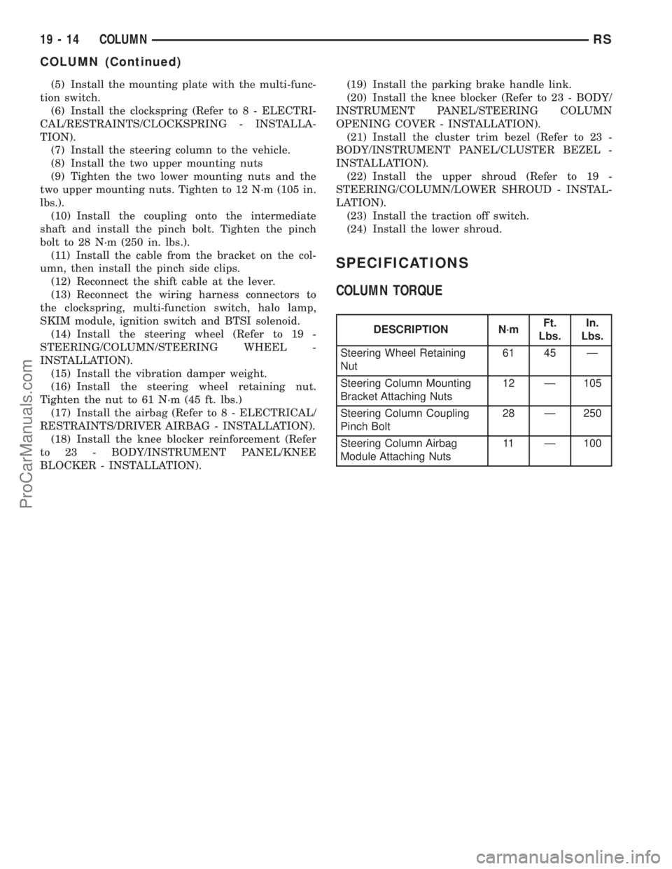
(9) Tighten the two lower mounting nuts and the
two upper mounting nuts. Tighten to 12 N´m (105 in.
lbs.).
(10) Install the coupling onto the intermediate
shaft and install the pinch bolt. Tighten the pinch
bolt to 28 N´m (250 in. lbs.).
(11) Install the cable from the bracket on the col-
umn, then install the pinch side clips.
(12) Reconnect the shift cable at the lever.
(13) Reconnect the wiring harness connectors to
the clockspring, multi-function switch, halo lamp,
SKIM module, ignition switch and BTSI solenoid.
(14) Install the steering wheel (Refer to 19 -
STEERING/COLUMN/STEERING WHEEL -
INSTALLATION).
(15) Install the vibration damper weight.
(16) Install the steering wheel retaining nut.
Tighten the nut to 61 N´m (45 ft. lbs.)
(17) Install the airbag (Refer to 8 - ELECTRICAL/
RESTRAINTS/DRIVER AIRBAG - INSTALLATION).
(18) Install the knee blocker reinforcement (Refer
to 23 - BODY/INSTRUMENT PANEL/KNEE
BLOCKER - INSTALLATION).(19) Install the parking brake handle link.
(20) Install the knee blocker (Refer to 23 - BODY/
INSTRUMENT PANEL/STEERING COLUMN
OPENING COVER - INSTALLATION).
(21) Install the cluster trim bezel (Refer to 23 -
BODY/INSTRUMENT PANEL/CLUSTER BEZEL -
INSTALLATION).
(22) Install the upper shroud (Refer to 19 -
STEERING/COLUMN/LOWER SHROUD - INSTAL-
LATION).
(23) Install the traction off switch.
(24) Install the lower shroud.
SPECIFICATIONS
COLUMN TORQUE
DESCRIPTION N´mFt.
Lbs.In.
Lbs.
Steering Wheel Retaining
Nut61 45 Ð
Steering Column Mounting
Bracket Attaching Nuts12 Ð 105
Steering Column Coupling
Pinch Bolt28 Ð 250
Steering Column Airbag
Module Attaching Nuts11 Ð 100
19 - 14 COLUMNRS
COLUMN (Continued)
ProCarManuals.com
Page 1518 of 2399
IGNITION SWITCH
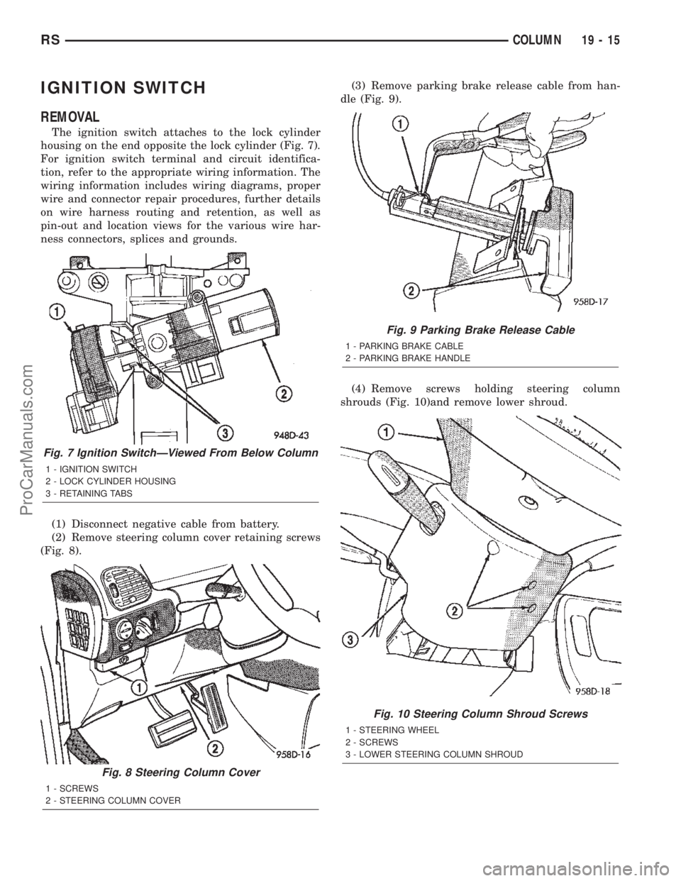
REMOVAL
The ignition switch attaches to the lock cylinder
housing on the end opposite the lock cylinder (Fig. 7).
For ignition switch terminal and circuit identifica-
tion, refer to the appropriate wiring information. The
wiring information includes wiring diagrams, proper
wire and connector repair procedures, further details
on wire harness routing and retention, as well as
pin-out and location views for the various wire har-
ness connectors, splices and grounds.
(1) Disconnect negative cable from battery.
(2) Remove steering column cover retaining screws
(Fig. 8).(3) Remove parking brake release cable from han-
dle (Fig. 9).
(4) Remove screws holding steering column
shrouds (Fig. 10)and remove lower shroud.
Fig. 7 Ignition SwitchÐViewed From Below Column
1 - IGNITION SWITCH
2 - LOCK CYLINDER HOUSING
3 - RETAINING TABS
Fig. 8 Steering Column Cover
1 - SCREWS
2 - STEERING COLUMN COVER
Fig. 9 Parking Brake Release Cable
1 - PARKING BRAKE CABLE
2 - PARKING BRAKE HANDLE
Fig. 10 Steering Column Shroud Screws
1 - STEERING WHEEL
2 - SCREWS
3 - LOWER STEERING COLUMN SHROUD
RSCOLUMN19-15
ProCarManuals.com
Page 1519 of 2399
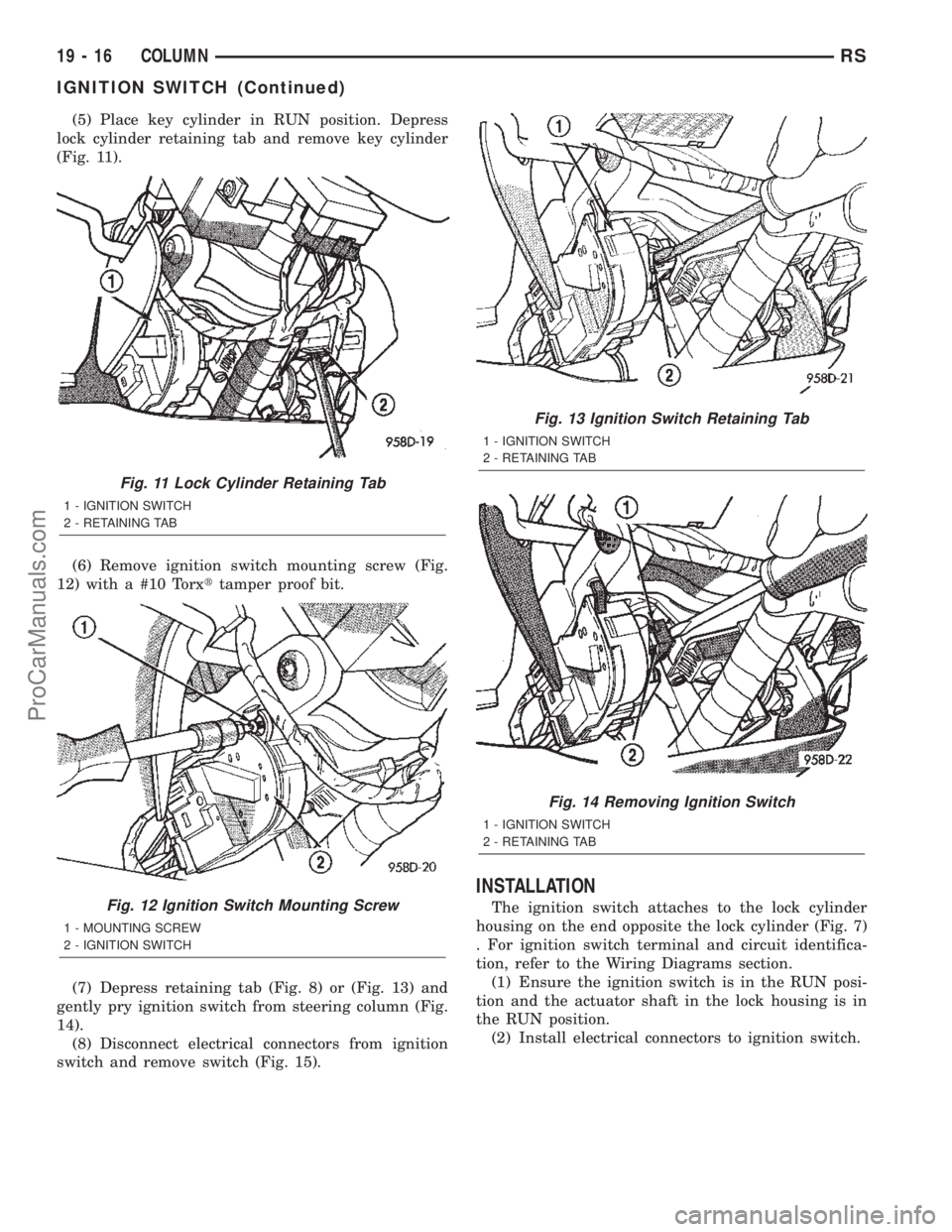
(5) Place key cylinder in RUN position. Depress
lock cylinder retaining tab and remove key cylinder
(Fig. 11).
(6) Remove ignition switch mounting screw (Fig.
12) with a #10 Torxttamper proof bit.
(7) Depress retaining tab (Fig. 8) or (Fig. 13) and
gently pry ignition switch from steering column (Fig.
14).
(8) Disconnect electrical connectors from ignition
switch and remove switch (Fig. 15).
INSTALLATION
The ignition switch attaches to the lock cylinder
housing on the end opposite the lock cylinder (Fig. 7)
. For ignition switch terminal and circuit identifica-
tion, refer to the Wiring Diagrams section.
(1) Ensure the ignition switch is in the RUN posi-
tion and the actuator shaft in the lock housing is in
the RUN position.
(2) Install electrical connectors to ignition switch.
Fig. 11 Lock Cylinder Retaining Tab
1 - IGNITION SWITCH
2 - RETAINING TAB
Fig. 12 Ignition Switch Mounting Screw
1 - MOUNTING SCREW
2 - IGNITION SWITCH
Fig. 13 Ignition Switch Retaining Tab
1 - IGNITION SWITCH
2 - RETAINING TAB
Fig. 14 Removing Ignition Switch
1 - IGNITION SWITCH
2 - RETAINING TAB
19 - 16 COLUMNRS
IGNITION SWITCH (Continued)
ProCarManuals.com