2002 CHRYSLER CARAVAN wiring
[x] Cancel search: wiringPage 2265 of 2399
a battery current output only when the compressor
clutch relay coil is de-energized.
Refer to the appropriate wiring information. The
wiring information includes wiring diagrams, proper
wire and connector repair procedures, further details
on wire harness routing and retention, as well as
pin-out and location views for the various wire har-
ness connectors, splices, and grounds.
DIAGNOSIS AND TESTING - COMPRESSOR
CLUTCH RELAY
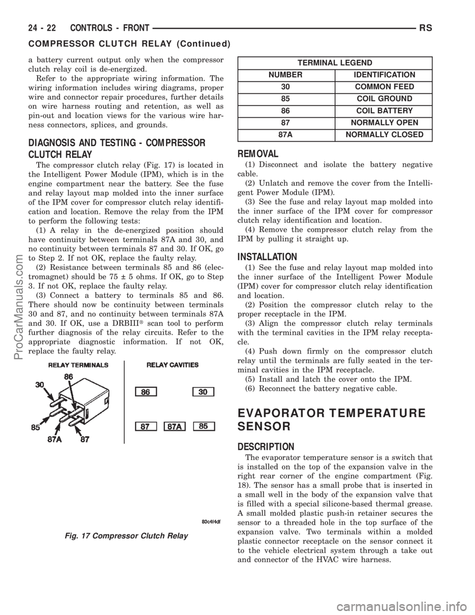
The compressor clutch relay (Fig. 17) is located in
the Intelligent Power Module (IPM), which is in the
engine compartment near the battery. See the fuse
and relay layout map molded into the inner surface
of the IPM cover for compressor clutch relay identifi-
cation and location. Remove the relay from the IPM
to perform the following tests:
(1) A relay in the de-energized position should
have continuity between terminals 87A and 30, and
no continuity between terminals 87 and 30. If OK, go
to Step 2. If not OK, replace the faulty relay.
(2) Resistance between terminals 85 and 86 (elec-
tromagnet) should be 75 5 ohms. If OK, go to Step
3. If not OK, replace the faulty relay.
(3) Connect a battery to terminals 85 and 86.
There should now be continuity between terminals
30 and 87, and no continuity between terminals 87A
and 30. If OK, use a DRBIIItscan tool to perform
further diagnosis of the relay circuits. Refer to the
appropriate diagnostic information. If not OK,
replace the faulty relay.
TERMINAL LEGEND
NUMBER IDENTIFICATION
30 COMMON FEED
85 COIL GROUND
86 COIL BATTERY
87 NORMALLY OPEN
87A NORMALLY CLOSED
REMOVAL
(1) Disconnect and isolate the battery negative
cable.
(2) Unlatch and remove the cover from the Intelli-
gent Power Module (IPM).
(3) See the fuse and relay layout map molded into
the inner surface of the IPM cover for compressor
clutch relay identification and location.
(4) Remove the compressor clutch relay from the
IPM by pulling it straight up.
INSTALLATION
(1) See the fuse and relay layout map molded into
the inner surface of the Intelligent Power Module
(IPM) cover for compressor clutch relay identification
and location.
(2) Position the compressor clutch relay to the
proper receptacle in the IPM.
(3) Align the compressor clutch relay terminals
with the terminal cavities in the IPM relay recepta-
cle.
(4) Push down firmly on the compressor clutch
relay until the terminals are fully seated in the ter-
minal cavities in the IPM receptacle.
(5) Install and latch the cover onto the IPM.
(6) Reconnect the battery negative cable.
EVAPORATOR TEMPERATURE
SENSOR
DESCRIPTION
The evaporator temperature sensor is a switch that
is installed on the top of the expansion valve in the
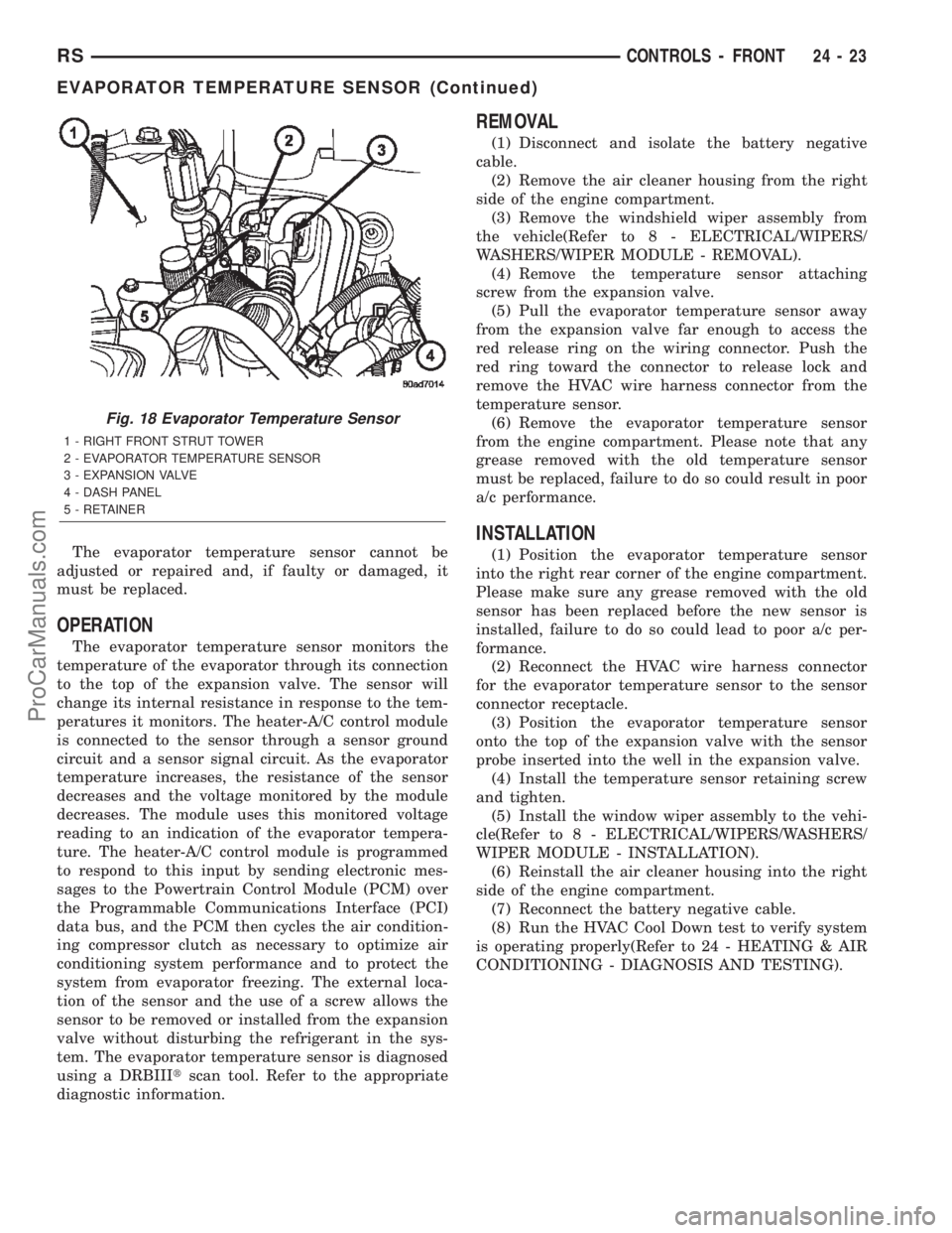
right rear corner of the engine compartment (Fig.
18). The sensor has a small probe that is inserted in
a small well in the body of the expansion valve that
is filled with a special silicone-based thermal grease.
A small molded plastic push-in retainer secures the
sensor to a threaded hole in the top surface of the
expansion valve. Two terminals within a molded
plastic connector receptacle on the sensor connect it
to the vehicle electrical system through a take out
and connector of the HVAC wire harness.
Fig. 17 Compressor Clutch Relay
24 - 22 CONTROLS - FRONTRS
COMPRESSOR CLUTCH RELAY (Continued)
ProCarManuals.com
Page 2266 of 2399
The evaporator temperature sensor cannot be
adjusted or repaired and, if faulty or damaged, it
must be replaced.
OPERATION
The evaporator temperature sensor monitors the
temperature of the evaporator through its connection
to the top of the expansion valve. The sensor will
change its internal resistance in response to the tem-
peratures it monitors. The heater-A/C control module
is connected to the sensor through a sensor ground
circuit and a sensor signal circuit. As the evaporator
temperature increases, the resistance of the sensor
decreases and the voltage monitored by the module
decreases. The module uses this monitored voltage
reading to an indication of the evaporator tempera-
ture. The heater-A/C control module is programmed
to respond to this input by sending electronic mes-
sages to the Powertrain Control Module (PCM) over
the Programmable Communications Interface (PCI)
data bus, and the PCM then cycles the air condition-
ing compressor clutch as necessary to optimize air
conditioning system performance and to protect the
system from evaporator freezing. The external loca-
tion of the sensor and the use of a screw allows the
sensor to be removed or installed from the expansion
valve without disturbing the refrigerant in the sys-
tem. The evaporator temperature sensor is diagnosed
using a DRBIIItscan tool. Refer to the appropriate
diagnostic information.
REMOVAL
(1) Disconnect and isolate the battery negative
cable.
(2) Remove the air cleaner housing from the right
side of the engine compartment.
(3) Remove the windshield wiper assembly from
the vehicle(Refer to 8 - ELECTRICAL/WIPERS/
WASHERS/WIPER MODULE - REMOVAL).
(4) Remove the temperature sensor attaching
screw from the expansion valve.
(5) Pull the evaporator temperature sensor away
from the expansion valve far enough to access the
red release ring on the wiring connector. Push the
red ring toward the connector to release lock and
remove the HVAC wire harness connector from the
temperature sensor.
(6) Remove the evaporator temperature sensor
from the engine compartment. Please note that any
grease removed with the old temperature sensor
must be replaced, failure to do so could result in poor
a/c performance.
INSTALLATION
(1) Position the evaporator temperature sensor
into the right rear corner of the engine compartment.
Please make sure any grease removed with the old
sensor has been replaced before the new sensor is
installed, failure to do so could lead to poor a/c per-
formance.
(2) Reconnect the HVAC wire harness connector
for the evaporator temperature sensor to the sensor
connector receptacle.
(3) Position the evaporator temperature sensor
onto the top of the expansion valve with the sensor
probe inserted into the well in the expansion valve.
(4) Install the temperature sensor retaining screw
and tighten.
(5) Install the window wiper assembly to the vehi-
cle(Refer to 8 - ELECTRICAL/WIPERS/WASHERS/
WIPER MODULE - INSTALLATION).
(6) Reinstall the air cleaner housing into the right
side of the engine compartment.
(7) Reconnect the battery negative cable.
(8) Run the HVAC Cool Down test to verify system
is operating properly(Refer to 24 - HEATING & AIR
CONDITIONING - DIAGNOSIS AND TESTING).
Fig. 18 Evaporator Temperature Sensor
1 - RIGHT FRONT STRUT TOWER
2 - EVAPORATOR TEMPERATURE SENSOR
3 - EXPANSION VALVE
4 - DASH PANEL
5 - RETAINER
RSCONTROLS - FRONT24-23
EVAPORATOR TEMPERATURE SENSOR (Continued)
ProCarManuals.com
Page 2276 of 2399
The blower motor relay terminals are connected to
the vehicle electrical system through a receptacle in
the Intelligent Power Module (IPM). The inputs and
outputs of the compressor clutch relay include:
²The common feed terminal (30) receives a bat-
tery current input from the battery through a B(+)
circuit at all times.
²The coil ground terminal (85) receives a ground
input through the front/rear blower motor relay con-
trol circuit only when the FCM electronically pulls
the control circuit to ground.
²The coil battery terminal (86) receives a battery
current input from the battery through a B(+) circuit
at all times.
²The normally open terminal (87) provides a bat-
tery current output to the blower motor resistor
(manual heater-A/C control) or blower power module
(automatic heater-A/C control) through a fuse in the
IPM on the fused rear blower motor relay output cir-
cuit only when the blower motor relay coil is ener-
gized.
²The normally closed terminal (87A) is not con-
nected to any circuit in this application, but provides
a battery current output only when the blower motor
relay coil is de-energized.
Refer to the appropriate wiring information. The
wiring information includes wiring diagrams, proper
wire and connector repair procedures, further details
on wire harness routing and retention, as well as
pin-out and location views for the various wire har-
ness connectors, splices, and grounds.
DIAGNOSIS AND TESTING - BLOWER MOTOR
RELAY
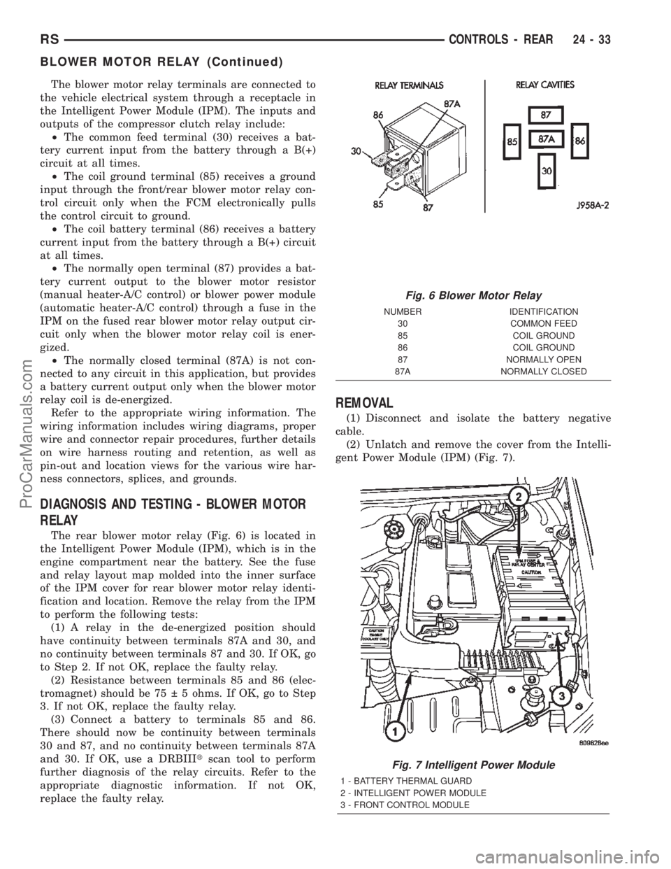
The rear blower motor relay (Fig. 6) is located in
the Intelligent Power Module (IPM), which is in the
engine compartment near the battery. See the fuse
and relay layout map molded into the inner surface
of the IPM cover for rear blower motor relay identi-
fication and location. Remove the relay from the IPM
to perform the following tests:
(1) A relay in the de-energized position should
have continuity between terminals 87A and 30, and
no continuity between terminals 87 and 30. If OK, go
to Step 2. If not OK, replace the faulty relay.
(2) Resistance between terminals 85 and 86 (elec-
tromagnet) should be 75 5 ohms. If OK, go to Step
3. If not OK, replace the faulty relay.
(3) Connect a battery to terminals 85 and 86.
There should now be continuity between terminals
30 and 87, and no continuity between terminals 87A
and 30. If OK, use a DRBIIItscan tool to perform
further diagnosis of the relay circuits. Refer to the
appropriate diagnostic information. If not OK,
replace the faulty relay.
REMOVAL
(1) Disconnect and isolate the battery negative
cable.
(2) Unlatch and remove the cover from the Intelli-
gent Power Module (IPM) (Fig. 7).
Fig. 6 Blower Motor Relay
NUMBER IDENTIFICATION
30 COMMON FEED
85 COIL GROUND
86 COIL GROUND
87 NORMALLY OPEN
87A NORMALLY CLOSED
Fig. 7 Intelligent Power Module
1 - BATTERY THERMAL GUARD
2 - INTELLIGENT POWER MODULE
3 - FRONT CONTROL MODULE
RSCONTROLS - REAR24-33
BLOWER MOTOR RELAY (Continued)
ProCarManuals.com
Page 2278 of 2399
DIAGNOSIS AND TESTING - BLOWER MOTOR
RESISTOR
Refer to the appropriate wiring information. The
wiring information includes wiring diagrams, proper
wire and connector repair procedures, details of wire
harness routing and retention, connector pin-out
information and location views for the various wire
harness connectors, splices and grounds.
(1) Disconnect and isolate the battery negative
cable.
(2) Disconnect the rear HVAC wire harness con-
nector for the blower motor resistor from the resistor
connector receptacle.
(3) Check for continuity between each of the
blower motor switch input terminals of the blower
motor resistor and the resistor output terminal. In
each case there should be continuity. If OK, repair
the wire harness circuits between the blower motor
switch and the blower motor resistor or the blower
motor pigtail wires as required. If not OK, replace
the faulty blower motor resistor.
REMOVAL
WARNING: THE BLOWER MOTOR RESISTOR MAY
GET VERY HOT DURING NORMAL OPERATION. IF
THE BLOWER MOTOR WAS TURNED ON, WAIT
FIVE MINUTES TO ALLOW THE BLOWER MOTOR
RESISTOR TO COOL BEFORE PERFORMING DIAG-
NOSIS OR SERVICE. FAILURE TO TAKE THIS PRE-
CAUTION CAN RESULT IN PERSONAL INJURY.
CAUTION: Do not operate the blower motor with the
blower motor resistor removed from the circuit.
Failure to take this precaution can result in vehicle
damage.
(1) Disconnect and isolate the battery negative
cable.
(2) Remove the right quarter trim panel and right
D-pillar trim panel from the quarter inner panel.
(Refer to 23 - BODY/INTERIOR/QUARTER TRIM
PANEL - REMOVAL).
(3) Disconnect the rear HVAC wire harness con-
nector for the blower motor resistor from the resistor
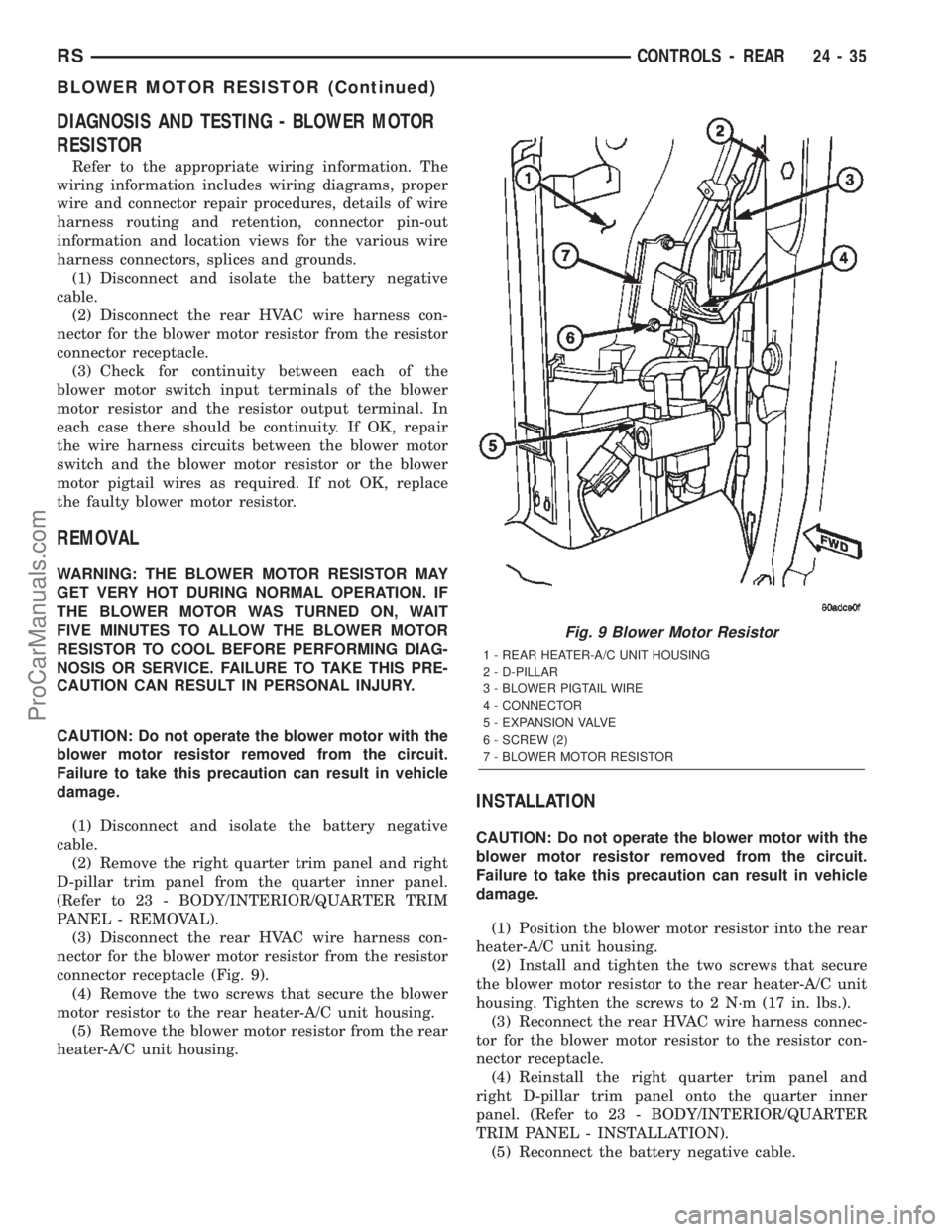
connector receptacle (Fig. 9).
(4) Remove the two screws that secure the blower
motor resistor to the rear heater-A/C unit housing.
(5) Remove the blower motor resistor from the rear
heater-A/C unit housing.
INSTALLATION
CAUTION: Do not operate the blower motor with the
blower motor resistor removed from the circuit.
Failure to take this precaution can result in vehicle
damage.
(1) Position the blower motor resistor into the rear
heater-A/C unit housing.
(2) Install and tighten the two screws that secure
the blower motor resistor to the rear heater-A/C unit
housing. Tighten the screws to 2 N´m (17 in. lbs.).
(3) Reconnect the rear HVAC wire harness connec-
tor for the blower motor resistor to the resistor con-
nector receptacle.
(4) Reinstall the right quarter trim panel and
right D-pillar trim panel onto the quarter inner
panel. (Refer to 23 - BODY/INTERIOR/QUARTER
TRIM PANEL - INSTALLATION).
(5) Reconnect the battery negative cable.
Fig. 9 Blower Motor Resistor
1 - REAR HEATER-A/C UNIT HOUSING
2 - D-PILLAR
3 - BLOWER PIGTAIL WIRE
4 - CONNECTOR
5 - EXPANSION VALVE
6 - SCREW (2)
7 - BLOWER MOTOR RESISTOR
RSCONTROLS - REAR24-35
BLOWER MOTOR RESISTOR (Continued)
ProCarManuals.com
Page 2290 of 2399
(4) Position the upper pivot of the recirculation
door into the opening at the top of the air inlet hous-
ing an dhold in place while the lower air inlet hous-
ing is placed in position.
(5) Install and tighten the three screws (from the
bottom) that secure the lower air intake housing to
the lower half of the evaporator housing. Tighten the
screws to 2 N´m (18 in. lbs.).
(6) Install and tighten the one screw that secures
the upper intake air housing to the lower intake air
housing. Tighten the screws to 2 N´m (18 in. lbs.).
(7) Install the recirculation actuator making cer-
tain that the splines are aligned and secure the
actuator with two screws and torque the to 2 N´m (18
in. lbs.). Route the wiring into the molded inn rout-
ing clips.
(8) Position the carpet into location and install the
lower right trim panel.
(9) Connect the blower motor pigtail wire harness
electrical connector back into either the power mod-
ule or resistor receptacle.
(10) Run the Heater-A/C Calibration procedure(Re-
fer to 24 - HEATING & AIR CONDITIONING/CON-
TROLS/A/C HEATER CONTROL - STANDARD
PROCEDURE).
(11) Run the HVAC Control Cooldown test(Refer to
24 - HEATING & AIR CONDITIONING - DIAGNO-
SIS AND TESTING).
DEFROSTER DUCT
REMOVAL
WARNING: ON VEHICLES EQUIPPED WITH AIR-
BAGS, DISABLE THE AIRBAG SYSTEM BEFORE
ATTEMPTING ANY STEERING WHEEL, STEERING
COLUMN, OR INSTRUMENT PANEL COMPONENT
DIAGNOSIS OR SERVICE. DISCONNECT AND ISO-
LATE THE BATTERY NEGATIVE (GROUND) CABLE,
THEN WAIT TWO MINUTES FOR THE AIRBAG SYS-
TEM CAPACITOR TO DISCHARGE BEFORE PER-
FORMING FURTHER DIAGNOSIS OR SERVICE. THIS
IS THE ONLY SURE WAY TO DISABLE THE AIRBAG
SYSTEM. FAILURE TO TAKE THE PROPER PRE-
CAUTIONS COULD RESULT IN ACCIDENTAL AIR-
BAG DEPLOYMENT AND POSSIBLE PERSONAL
INJURY.
(1) Disconnect and isolate the battery negative
cable.
(2) Remove the instrument panel from the vehicle.
(Refer to 23 - BODY/INSTRUMENT PANEL/IN-
STRUMENT PANEL ASSEMBLY - REMOVAL).
(3) Place the instrument panel face down on a
suitable work surface. Be certain to take the properprecautions to protect the face of the instrument
panel from cosmetic damage.
(4) Remove the fasteners that secure the defroster
duct to the instrument panel armature.
(5) Remove the defroster duct from the instrument
panel.
INSTALLATION
WARNING: ON VEHICLES EQUIPPED WITH AIR-
BAGS, DISABLE THE AIRBAG SYSTEM BEFORE
ATTEMPTING ANY STEERING WHEEL, STEERING
COLUMN, OR INSTRUMENT PANEL COMPONENT
DIAGNOSIS OR SERVICE. DISCONNECT AND ISO-
LATE THE BATTERY NEGATIVE (GROUND) CABLE,
THEN WAIT TWO MINUTES FOR THE AIRBAG SYS-
TEM CAPACITOR TO DISCHARGE BEFORE PER-
FORMING FURTHER DIAGNOSIS OR SERVICE. THIS
IS THE ONLY SURE WAY TO DISABLE THE AIRBAG
SYSTEM. FAILURE TO TAKE THE PROPER PRE-
CAUTIONS COULD RESULT IN ACCIDENTAL AIR-
BAG DEPLOYMENT AND POSSIBLE PERSONAL
INJURY.
(1) Position the defroster duct to the instrument
panel.
(2) Install the fasteners that secure the defroster
duct to the instrument panel armature.
(3) Reinstall the instrument panel in the vehicle.
(Refer to 23 - BODY/INSTRUMENT PANEL/IN-
STRUMENT PANEL ASSEMBLY - INSTALLA-
TION).
(4) Reconnect the battery negative cable.
DEMISTER DUCTS
REMOVAL
WARNING: ON VEHICLES EQUIPPED WITH AIR-
BAGS, DISABLE THE AIRBAG SYSTEM BEFORE
ATTEMPTING ANY STEERING WHEEL, STEERING
COLUMN, OR INSTRUMENT PANEL COMPONENT
DIAGNOSIS OR SERVICE. DISCONNECT AND ISO-
LATE THE BATTERY NEGATIVE (GROUND) CABLE,
THEN WAIT TWO MINUTES FOR THE AIRBAG SYS-
TEM CAPACITOR TO DISCHARGE BEFORE PER-
FORMING FURTHER DIAGNOSIS OR SERVICE. THIS
IS THE ONLY SURE WAY TO DISABLE THE AIRBAG
SYSTEM. FAILURE TO TAKE THE PROPER PRE-
CAUTIONS COULD RESULT IN ACCIDENTAL AIR-
BAG DEPLOYMENT AND POSSIBLE PERSONAL
INJURY.
(1) Disconnect and isolate the battery negative
cable.
RSDISTRIBUTION - FRONT24-47
BLOWER MOTOR (Continued)
ProCarManuals.com
Page 2312 of 2399
and the heat from the air is absorbed by the refrig-
erant. Heat absorption causes the refrigerant to boil
and vaporize. The refrigerant becomes a low-pressure
gas when it leaves the evaporator.
REMOVAL
WARNING: REFER TO THE APPLICABLE WARN-
INGS AND CAUTIONS FOR THIS SYSTEM BEFORE
PERFORMING THE FOLLOWING OPERATION.
(Refer to 24 - HEATING & AIR CONDITIONING/
PLUMBING - FRONT - WARNING - A/C PLUMBING),
(Refer to 24 - HEATING & AIR CONDITIONING/
PLUMBING - FRONT - CAUTION - A/C PLUMBING),
and (Refer to 24 - HEATING & AIR CONDITIONING/
PLUMBING - FRONT - WARNING - HEATER PLUMB-
ING).
(1) Remove the HVAC unit housing from the vehi-
cle. (Refer to 24 - HEATING & AIR CONDITION-
ING/DISTRIBUTION - FRONT/HVAC HOUSING -
REMOVAL).
(2) Remove the heater core tubes from the heater
core. (Refer to 24 - HEATING & AIR CONDITION-
ING/PLUMBING - FRONT/HEATER CORE -
REMOVAL - HEATER CORE TUBES).
(3) Remove and discard the foam seal from the
HVAC housing seal flange around the fresh air inlet
opening and the expansion valve/evaporator tube
opening on the dash panel side of the unit.
(4) Remove the expansion valve from the evapora-
tor inlet and outlet tube fittings. (Refer to 24 -
HEATING & AIR CONDITIONING/PLUMBING -
FRONT/EXPANSION VALVE - REMOVAL).
(5) Disconnect the HVAC wire harness connector
for the blower motor from the motor connector recep-
tacle on the bottom of the outboard end of the evap-
orator housing.
(6) Disengage the HVAC wire harness from the
routing clips molded into the outside of the HVAC
housing components.
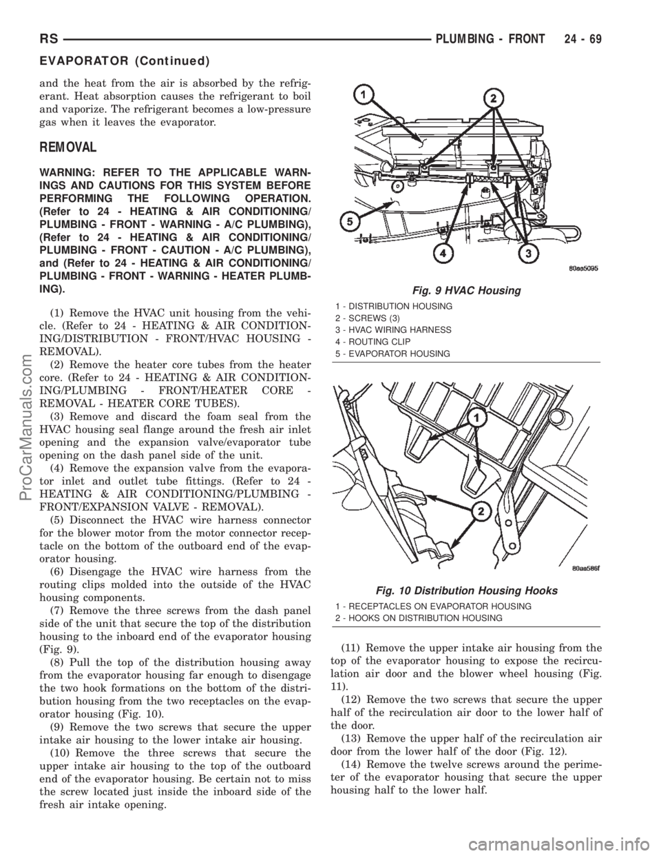
(7) Remove the three screws from the dash panel
side of the unit that secure the top of the distribution
housing to the inboard end of the evaporator housing
(Fig. 9).
(8) Pull the top of the distribution housing away
from the evaporator housing far enough to disengage
the two hook formations on the bottom of the distri-
bution housing from the two receptacles on the evap-
orator housing (Fig. 10).
(9) Remove the two screws that secure the upper
intake air housing to the lower intake air housing.
(10) Remove the three screws that secure the
upper intake air housing to the top of the outboard
end of the evaporator housing. Be certain not to miss
the screw located just inside the inboard side of the
fresh air intake opening.(11) Remove the upper intake air housing from the
top of the evaporator housing to expose the recircu-
lation air door and the blower wheel housing (Fig.
11).
(12) Remove the two screws that secure the upper
half of the recirculation air door to the lower half of
the door.
(13) Remove the upper half of the recirculation air
door from the lower half of the door (Fig. 12).
(14) Remove the twelve screws around the perime-
ter of the evaporator housing that secure the upper
housing half to the lower half.
Fig. 9 HVAC Housing
1 - DISTRIBUTION HOUSING
2 - SCREWS (3)
3 - HVAC WIRING HARNESS
4 - ROUTING CLIP
5 - EVAPORATOR HOUSING
Fig. 10 Distribution Housing Hooks
1 - RECEPTACLES ON EVAPORATOR HOUSING
2 - HOOKS ON DISTRIBUTION HOUSING
RSPLUMBING - FRONT24-69
EVAPORATOR (Continued)
ProCarManuals.com
Page 2352 of 2399
DIESEL SUPPLEMENTAL HEATER - DCHA - BUX
TABLE OF CONTENTS
page page
DIESEL SUPPLEMENTAL HEATER - DCHA -
BUX
DESCRIPTION........................109
OPERATION..........................109
DIAGNOSIS AND TESTING - DIESEL
SUPPLEMENTAL HEATER - DCHA........110
EXHAUST TUBE
REMOVAL............................110
INSTALLATION........................110
FUEL DOSING PUMP
DESCRIPTION........................111
OPERATION..........................111
REMOVAL............................111
INSTALLATION........................111FUEL LINE
STANDARD PROCEDURE - CLEANING.....112
REMOVAL............................112
INSTALLATION........................112
HEATER UNIT
REMOVAL............................114
INSTALLATION........................114
SUPPLEMENTAL DIESEL HEATER WIRING
REMOVAL............................115
INSTALLATION........................115
AIR INTAKE PIPE
REMOVAL............................115
INSTALLATION........................116
DIESEL SUPPLEMENTAL
HEATER - DCHA - BUX
DESCRIPTION
Vehicles equipped with the optional diesel engine
are also equipped with a supplemental heater unit.
This unit is mounted under the vehicle and operates
similar to an oil fired furnace. The heater burns
small amounts of fuel to provide additional heat to
the coolant. Coolant is routed from the engine, to the
supplemental heater, and then to the front heater
core. This provides additional heat to the passenger
compartment. The system is interfaced to the vehi-
cles on-board computer systems and DRB-III diag-
nostics.
OPERATION
The supplemental heater unit is activated via the
temperature slide control or knob on the vehicle
HVAC control unit. If the control slide or knob is
moved to or above the upper set point the heater is
activated. The unit can operate in a full or partial
load range as well as an idle mode all dependent on
the engine coolant temperature. The heater unit will
also turn off if the HVAC temperature control is low-
ered to less than the lower set point. The heater unit
can take up to three minutes to completely shut
down when either the heater temperature is set
below the lower set point or the vehicle ignition is
shut down.
RSDIESEL SUPPLEMENTAL HEATER - DCHA - BUX24 - 109
ProCarManuals.com
Page 2357 of 2399
(7) With the DRBIIItin Cabin Heater, select Sys-
tem Tests and Dosing Pump Prime. Allow the Dosing
Pump to run for the full 45 second cycle time. When
the 45 second cycle is complete, press Page Back on
the DRBIIItkey pad to exit the Dosing Pump Prime.
The Dosing Pump priming procedure is now com-
plete.
HEATER UNIT
REMOVAL
WARNING: ALLOW THE DCHA TO COOL BEFORE
PERFORMING A COMPONENT INSPECTION/REPAIR
OR REPLACEMENT. FAILURE TO FOLLOW THESE
INSTRUCTIONS MAY RESULT IN PERSONAL
INJURY.
WARNING: ALLOW THE EXHAUST SYSTEM TO
COOL BEFORE PERFORMING A COMPONENT
INSPECTION/REPAIR OR REPLACEMENT. FAILURE
TO FOLLOW THESE INSTRUCTION MAY RESULT IN
PERSONAL INJURY.
(1) Elevate the vehicle on a hoist/lift taking note of
heater exhaust tube flexible section.
(2) Drain cooling system(Refer to 7 - COOLING -
STANDARD PROCEDURE).
(3) Carefully open one hose to the underbody tube
assembly and drain the remaining coolant. A salvage
hose is a good idea to control the residual coolant, as
flow will occur from both the heater and the hose and
tube assemblies.
(4) Remove the second hose from the underbody
hose and tube assembly.
(5) Loosen the hose and tube assembly from the
toe-board cross member at two locations.
(6) Disconnect the electrical connector from the
body harness near the toe board cross member and
rail.
(7) Remove the wiring harness from the toe board
cross member(Refer to 24 - HEATING & AIR CON-
DITIONING/CABIN HEATER/HEATER UNIT -
REMOVAL).
(8) Open the fuel fill cap. Disconnect the rubber
fuel hose between the body tube assembly and the
fuel pump nipple at the body tube joint. A minimal
amount of fuel may flow from the open port.
NOTE: Utilize an approved fuel storage container to
catch any residual fuel.
(9) Loosen the two M8 fasteners at the rail. Take
care to notice that the exhaust tube bracket tab is on
top of the heater bracket.(10) Remove the heater exhaust tube flex section
from the exhaust tube by loosening the M6 bolt of
the clamp assembly. Remove the hose from the
exhaust tube. Removal of the rail tube assembly may
aid in this service operation.(Refer to 24 - HEATING
& AIR CONDITIONING/CABIN HEATER/EXHAUST
TUBE - REMOVAL).
(11) Remove seat hex nut at the heater mounting
flange to cross member.
(12) Loosen the remaining M6 and M8 fasteners
which mount the exhaust tube assembly to the vehi-
cle.
(a) Install a suitable cabin heater support device
under the cabin heater and secure the cabin heater
to the device.
(13) Loosen the remaining three M6 fasteners to
the cross members.
(14) Remove the loosened fasteners that support
the heater while supporting the weight of the heater.
(15) Swing the unit mounting bracket from
between the exhaust bracket and rail mounting loca-
tion. Drain any residual coolant from the heater unit.
(16) Lower the cabin heater and remove from the
supporting device and place on a suitable work area.
INSTALLATION
(1) Install the unit mounting bracket between the
exhaust bracket and the rail mounting location.
(2) Install the fasteners that support the heater
while supporting the weight of the heater.
(3) Install the three M6 fasteners to the cross
members. Tighten the M6 fasteners to 7 Nm (5 ft.
lbs.).
(4) Tighten the remaining M6 fasteners to 7 Nm (5
ft. lbs.) and the M8 fasteners to 23 Nm (17 ft. lbs.)
which mount the exhaust tube assembly to the vehi-
cle.
(5) Install the seat hex nut at the heater mounting
flange to the cross members. Tighten to 60 Nm (44 ft.
lbs.)
(6) Install the heater exhaust tube flex section to
the exhaust tube by tightening the M6 bolt of the
clamp assembly. Install the hose to the exhaust tube.
(7) Tighten the two M8 fasteners at the rail to 23
Nm (17 ft. lbs.). Taking care so that the exhaust tube
bracket tab is on the top of the heater bracket.
(8) Install the wiring harness(Refer to 24 - HEAT-
ING & AIR CONDITIONING/CABIN HEATER/
HEATER UNIT - INSTALLATION).
(9) Tighten the hose and tube assembly to the toe-
board cross member at two locations.
(10) Install the second hose to the underbody hose
and tube assembly.
(11) Connect the rubber fuel hose between the
body tube assembly and the fuel pump nipple at the
body tube joint. Close the fuel fill cap.
24 - 114 DIESEL SUPPLEMENTAL HEATER - DCHA - BUXRS
FUEL LINE (Continued)
ProCarManuals.com