2002 CHRYSLER CARAVAN wiring
[x] Cancel search: wiringPage 1526 of 2399
(10) Install the cluster trim bezel (Refer to 23 -
BODY/INSTRUMENT PANEL/CLUSTER BEZEL -
INSTALLATION).
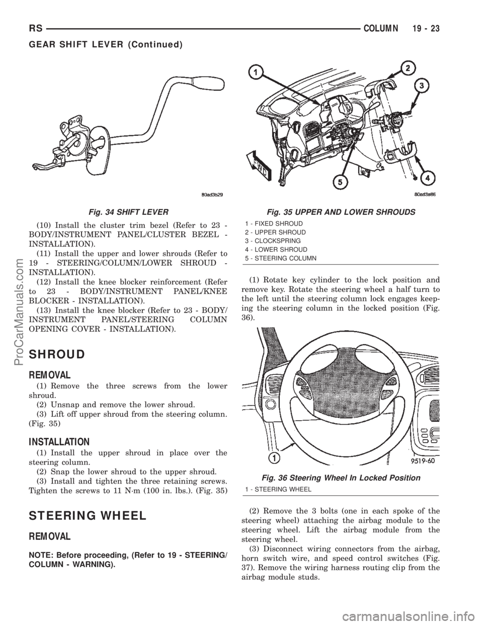
(11) Install the upper and lower shrouds (Refer to
19 - STEERING/COLUMN/LOWER SHROUD -
INSTALLATION).
(12) Install the knee blocker reinforcement (Refer
to 23 - BODY/INSTRUMENT PANEL/KNEE
BLOCKER - INSTALLATION).
(13) Install the knee blocker (Refer to 23 - BODY/
INSTRUMENT PANEL/STEERING COLUMN
OPENING COVER - INSTALLATION).
SHROUD
REMOVAL
(1) Remove the three screws from the lower
shroud.
(2) Unsnap and remove the lower shroud.
(3) Lift off upper shroud from the steering column.
(Fig. 35)
INSTALLATION
(1) Install the upper shroud in place over the
steering column.
(2) Snap the lower shroud to the upper shroud.
(3) Install and tighten the three retaining screws.
Tighten the screws to 11 N´m (100 in. lbs.). (Fig. 35)
STEERING WHEEL
REMOVAL
NOTE: Before proceeding, (Refer to 19 - STEERING/
COLUMN - WARNING).(1) Rotate key cylinder to the lock position and
remove key. Rotate the steering wheel a half turn to
the left until the steering column lock engages keep-
ing the steering column in the locked position (Fig.
36).
(2) Remove the 3 bolts (one in each spoke of the
steering wheel) attaching the airbag module to the
steering wheel. Lift the airbag module from the
steering wheel.
(3) Disconnect wiring connectors from the airbag,
horn switch wire, and speed control switches (Fig.
37). Remove the wiring harness routing clip from the
airbag module studs.
Fig. 34 SHIFT LEVERFig. 35 UPPER AND LOWER SHROUDS
1 - FIXED SHROUD
2 - UPPER SHROUD
3 - CLOCKSPRING
4 - LOWER SHROUD
5 - STEERING COLUMN
Fig. 36 Steering Wheel In Locked Position
1 - STEERING WHEEL
RSCOLUMN19-23
GEAR SHIFT LEVER (Continued)
ProCarManuals.com
Page 1527 of 2399
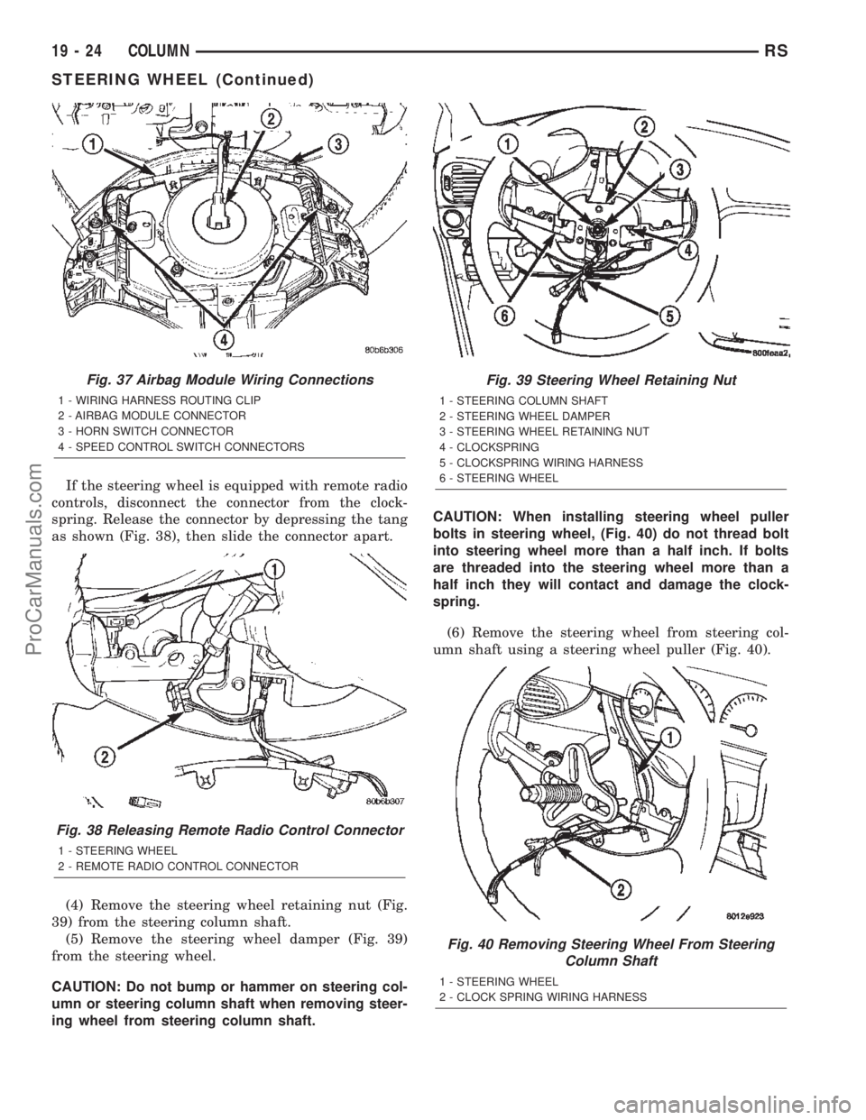
If the steering wheel is equipped with remote radio
controls, disconnect the connector from the clock-
spring. Release the connector by depressing the tang
as shown (Fig. 38), then slide the connector apart.
(4) Remove the steering wheel retaining nut (Fig.
39) from the steering column shaft.
(5) Remove the steering wheel damper (Fig. 39)
from the steering wheel.
CAUTION: Do not bump or hammer on steering col-
umn or steering column shaft when removing steer-
ing wheel from steering column shaft.CAUTION: When installing steering wheel puller
bolts in steering wheel, (Fig. 40) do not thread bolt
into steering wheel more than a half inch. If bolts
are threaded into the steering wheel more than a
half inch they will contact and damage the clock-
spring.
(6) Remove the steering wheel from steering col-
umn shaft using a steering wheel puller (Fig. 40).
Fig. 37 Airbag Module Wiring Connections
1 - WIRING HARNESS ROUTING CLIP
2 - AIRBAG MODULE CONNECTOR
3 - HORN SWITCH CONNECTOR
4 - SPEED CONTROL SWITCH CONNECTORS
Fig. 38 Releasing Remote Radio Control Connector
1 - STEERING WHEEL
2 - REMOTE RADIO CONTROL CONNECTOR
Fig. 39 Steering Wheel Retaining Nut
1 - STEERING COLUMN SHAFT
2 - STEERING WHEEL DAMPER
3 - STEERING WHEEL RETAINING NUT
4 - CLOCKSPRING
5 - CLOCKSPRING WIRING HARNESS
6 - STEERING WHEEL
Fig. 40 Removing Steering Wheel From Steering
Column Shaft
1 - STEERING WHEEL
2 - CLOCK SPRING WIRING HARNESS
19 - 24 COLUMNRS
STEERING WHEEL (Continued)
ProCarManuals.com
Page 1528 of 2399

INSTALLATION
CAUTION: Do not force steering wheel onto steer-
ing column shaft by driving it on. Pull steering
wheel down onto shaft using only the steering
wheel retaining nut.
(1) Align master splines on steering wheel and
steering shaft, and flats on steering wheel with for-
mations on clockspring. Install the steering wheel on
the steering column shaft. All wiring leads from the
clockspring must be routed as shown (Fig. 41).NOTE: Before installing the damper on the steering
wheel, inspect the damper to ensure the rubber iso-
lator on the damper is not deteriorated or damaged.
If the damper is installed with a damaged isolator a
buzz, squeak or rattle condition may develop.
(2) Install the steering wheel damper on the steer-
ing wheel. When damper is installed, it must be posi-
tioned on the steering wheel as shown in (Fig. 39).
(3) Install the steering wheel retaining nut.
Tighten the steering wheel retaining nut to a torque
of 61 N´m (45 ft. lbs.).
(4) Connect the wiring lead from the clockspring to
the remote radio control connector (Fig. 38).
(5) Install the wiring leads from the clockspring on
the airbag, horn switch wire, and speed control
switches (Fig. 37). Attach the wire routing clip to the
studs on the airbag module.
(6) Install the airbag module in the steering wheel.
(7) Install the 3 bolts (1 in each spoke of the steer-
ing wheel) attaching the airbag module to the steer-
ing wheel. Tighten the 3 airbag module attaching
nuts to a torque of 11 N´m (100 in. lbs.).
Fig. 41 Steering Wheel And Clock Spring Wire
Routing
1 - STEERING WHEEL
2 - CLOCK SPRING
3 - CLOCK SPRING WIRING LEADS
RSCOLUMN19-25
STEERING WHEEL (Continued)
ProCarManuals.com
Page 1541 of 2399
(2) Fill the fluid reservoir to the proper level and
let the fluid settle for at least two (2) minutes.
(3) Start the engine and let run for a few seconds,
then turn the engine off.
(4) Add fluid if necessary. Repeat the above steps
until the fluid level remains constant after running
the engine.
(5) Raise the front wheels off the ground.
(6) Start the engine.
(7) Slowly turn the steering wheel right and left,
lightly contacting the wheel stops.
(8) Add fluid if necessary.
(9) Lower the vehicle, then turn the steering wheel
slowly from lock-to-lock.
(10) Stop the engine. Check the fluid level and
refill as required.
(11) If the fluid is extremely foamy, allow the vehi-
cle to stabilize a few minutes, then repeat the above
procedure.
REMOVAL
REMOVAL - PUMP (2.4L ENGINE)
(1) Remove the (-) negative battery cable from the
battery and isolate cable.
(2) Remove the cap from the power steering fluid
reservoir.
(3) Using a siphon pump, remove as much power
steering fluid as possible from the power steering
fluid reservoir.
(4) Raise the vehicle on jack stands or centered on
a frame contact type hoist. See Hoisting in Lubrica-
tion and Maintenance.
(5) Disconnect the oxygen sensor wiring harness
from the vehicle wiring harness at the rear engine
mount bracket.
NOTE: The exhaust system needs to be removed
from the engine to allow for an area to remove the
power steering pump from the vehicle.
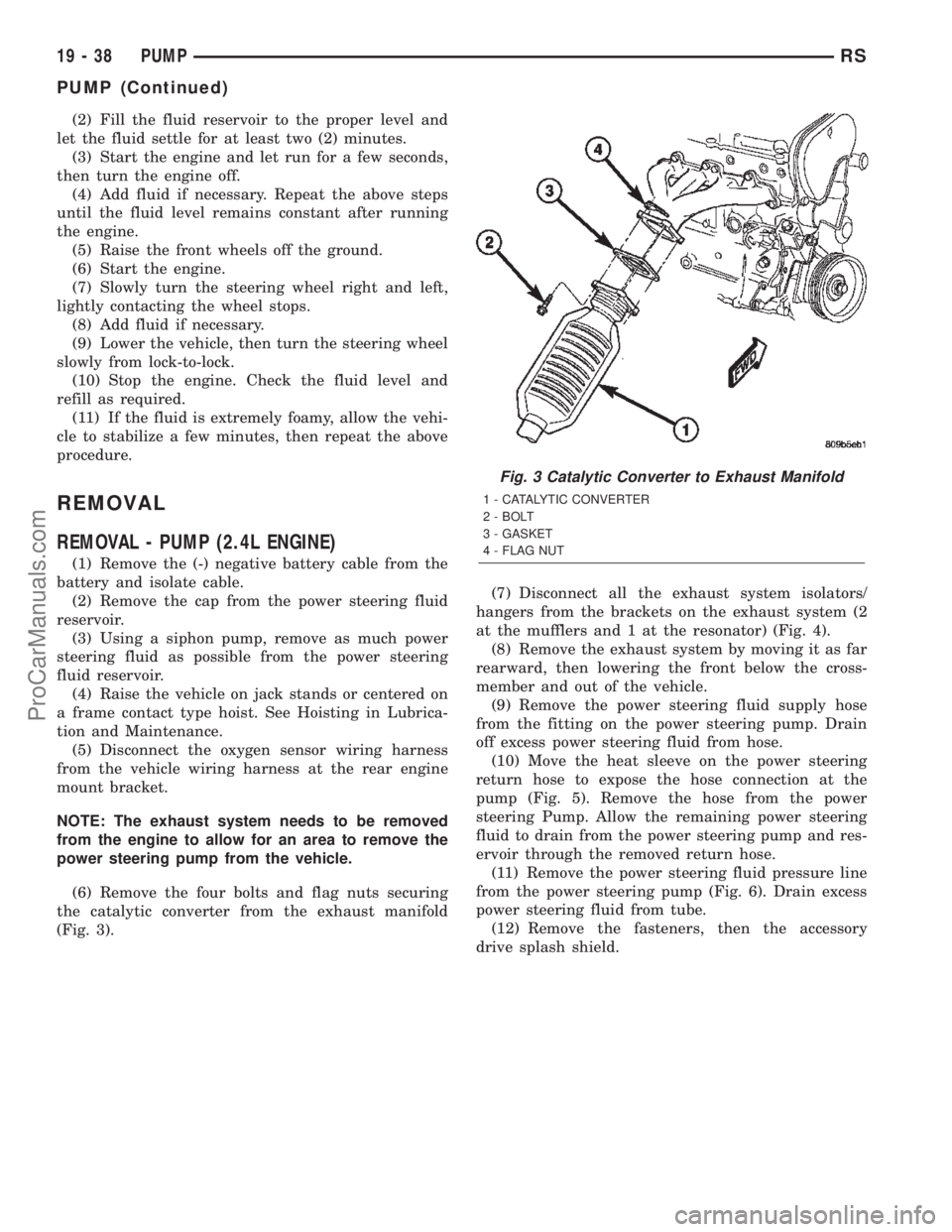
(6) Remove the four bolts and flag nuts securing
the catalytic converter from the exhaust manifold
(Fig. 3).(7) Disconnect all the exhaust system isolators/
hangers from the brackets on the exhaust system (2
at the mufflers and 1 at the resonator) (Fig. 4).
(8) Remove the exhaust system by moving it as far
rearward, then lowering the front below the cross-
member and out of the vehicle.
(9) Remove the power steering fluid supply hose
from the fitting on the power steering pump. Drain
off excess power steering fluid from hose.
(10) Move the heat sleeve on the power steering
return hose to expose the hose connection at the
pump (Fig. 5). Remove the hose from the power
steering Pump. Allow the remaining power steering
fluid to drain from the power steering pump and res-
ervoir through the removed return hose.
(11) Remove the power steering fluid pressure line
from the power steering pump (Fig. 6). Drain excess
power steering fluid from tube.
(12) Remove the fasteners, then the accessory
drive splash shield.
Fig. 3 Catalytic Converter to Exhaust Manifold
1 - CATALYTIC CONVERTER
2 - BOLT
3 - GASKET
4 - FLAG NUT
19 - 38 PUMPRS
PUMP (Continued)
ProCarManuals.com
Page 1546 of 2399
INSTALLATION
INSTALLATION - PUMP (2.4L ENGINE)
(1) Install power steering pump back in vehicle
using the reverse order of its removal through the
exhaust tunnel of the vehicle.
(2) Install the power steering pump on its cast
mounting bracket (Fig. 7), then install the nut and
bolt attaching the front bracket to the cast bracket
(Fig. 8).Do not fully tighten at this time..
(3) Install the rear nut (Fig. 7).
(4) Install the power steering pump drive belt on
pulley and adjust (Refer to 7 - COOLING/ACCES-
SORY DRIVE/DRIVE BELTS - INSTALLATION).
(5) Tighten the two adjustment slot bolts and the
one pivot bolt to 54 N´m (40 ft. lbs.) torque.
(6) Install the accessory drive splash shield.
NOTE: Before installing power steering fluid pres-
sure hose on power steering pump, inspect the
O-ring on the pressure hose for damage and
replace if necessary.
(7) Install the power steering fluid pressure line
onto the output fitting of the power steering pump
(Fig. 6). Tighten the pressure line to pump fitting
tube nut to a torque of 31 N´m (275 in. lbs.).
(8) Install the power steering fluid low pressure
return hose on the power steering pump low pressure
fitting (Fig. 6).Be sure hose clamps are properly
reinstalled.
(9) Install the power steering fluid supply hose on
the power steering pump fluid fitting.Be sure hose
is clear of accessory drive belts all hose clamps
are properly reinstalled.
CAUTION: Heat sleeve must cover entire rubber
portion of return hose to ensure desired thermal
protection from exhaust.
(10) Properly position the protective heat sleeve
over the power steering return hose. Securely tie
strap the heat sleeve to the power steering hose to
keep in it's proper position.
(11) Install the exhaust system (Fig. 4). Install all
exhaust system isolators/hangers on the exhaust sys-
tem brackets, then the four bolts and flag nuts (Fig.
3).
(12) Connect the oxygen sensor wiring harness to
the vehicle wiring harness.
(13) Lower vehicle.
(14) Connect the negative battery cable on the
negative battery post.
(15) Perform the POWER STEERING PUMP INI-
TIAL OPERATION procedure to properly fill and
bleed the power steering system. (Refer to 19 -
STEERING/PUMP - STANDARD PROCEDURE)(16) Inspect for leaks.
INSTALLATION - PUMP (3.3L/3.8L ENGINE)
(1) Install power steering pump back in vehicle
using the reverse order of its removal through the
engine compartment of the vehicle.
(2) Install the power steering pump on its mount-
ing bracket.
(3) Install the 3 front power steering pump mount-
ing bolts (Fig. 11). Tighten the 3 front power steering
pump mounting bolts to a torque of 54 N´m (40 ft.
lbs.).
NOTE: Before installing power steering pressure
hose on power steering pump, inspect the O-ring
on the power steering pressure hose for damage
and replace if required.
(4) Install the power steering fluid pressure line
into the pressure output fitting of the power steering
pump (Fig. 10).Do not fully tighten tube nut at
this time.
(5) Install the power steering fluid supply hose on
the power steering pump supply fitting (Fig. 10).Be
sure hose clamp is properly installed.
(6) Raise the vehicle.
(7) Install the routing clip on the engine for the
pressure hose (Fig. 9) and tighten fastener.
(8) Install the serpentine drive belt (Refer to 7 -
COOLING/ACCESSORY DRIVE/DRIVE BELTS -
INSTALLATION).
(9) Install the drive belt splash shield.
(10) Lower the vehicle.
(11) Tighten the pressure line to pump pressure
fitting tube nut to a torque of 31 N´m (275 in. lbs.).
(12) Install the wiper module (unit)(Refer to 8 -
ELECTRICAL/WIPERS/WASHERS/WIPER MOD-
ULE - INSTALLATION).
(13) Connect the negative battery cable on the
negative battery post.
(14) Fill and bleed the power steering system
using the Power Steering Pump Initial Operation
Procedure (Refer to 19 - STEERING/PUMP - STAN-
DARD PROCEDURE).
(15) Inspect for leaks.
INSTALLATION - PUMP (2.5L DIESEL)
(1) Install the power steering pump on its cast
mounting bracket.
(2) Install the three front power steering pump
mounting bolts. Tighten the mounting bolts to a
torque of 54 N´m (40 ft. lbs.).
(3) Install the rear mounting bolt fastening the
stamped bracket to the cast bracket (Fig. 13).
Tighten the mounting bolt to a torque of 54 N´m (40
ft. lbs.).
RSPUMP19-43
PUMP (Continued)
ProCarManuals.com
Page 1587 of 2399
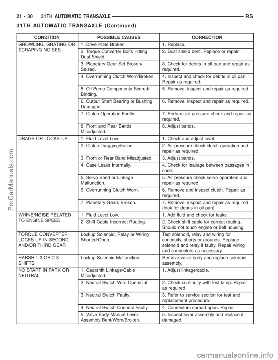
CONDITION POSSIBLE CAUSES CORRECTION
GROWLING, GRATING OR
SCRAPING NOISES1. Drive Plate Broken. 1. Replace.
2. Torque Converter Bolts Hitting
Dust Shield.2. Dust shield bent. Replace or repair.
3. Planetary Gear Set Broken/
Seized.3. Check for debris in oil pan and repair as
required.
4. Overrunning Clutch Worn/Broken. 4. Inspect and check for debris in oil pan.
Repair as required.
5. Oil Pump Components Scored/
Binding.5. Remove, inspect and repair as required.
6. Output Shaft Bearing or Bushing
Damaged.6. Remove, inspect and repair as required.
7. Clutch Operation Faulty. 7. Perform air pressure check and repair as
required.
8. Front and Rear Bands
Misadjusted.8. Adjust bands.
DRAGS OR LOCKS UP 1. Fluid Level Low. 1. Check and adjust level.
2. Clutch Dragging/Failed 2. Air pressure check clutch operation and
repair as required.
3. Front or Rear Band Misadjusted. 3. Adjust bands.
4. Case Leaks Internally. 4. Check for leakage between passages in
case.
5. Servo Band or Linkage
Malfunction.5. Air pressure check servo operation and
repair as required.
6. Overrunning Clutch Worn. 6. Remove and inspect clutch. Repair as
required.
7. Planetary Gears Broken. 7. Remove, inspect and repair as required
(look for debris in oil pan).
WHINE/NOISE RELATED
TO ENGINE SPEED1. Fluid Level Low. 1. Add fluid and check for leaks.
2. Shift Cable Incorrect Routing. 2. Check shift cable for correct routing.
Should not touch engine or bell housing.
TORQUE CONVERTER
LOCKS UP IN SECOND
AND/OR THIRD GEARLockup Solenoid, Relay or Wiring
Shorted/Open.Test solenoid, relay and wiring for
continuity, shorts or grounds. Replace
solenoid and relay if faulty. Repair wiring
and connectors as necessary.
HARSH 1-2 OR 2-3
SHIFTSLockup Solenoid Malfunction. Remove valve body and replace solenoid
assembly.
NO START IN PARK OR
NEUTRAL1. Gearshift Linkage/Cable
Misadjusted.1. Adjust linkage/cable.
2. Neutral Switch Wire Open/Cut. 2. Check continuity with test lamp. Repair
as required.
3. Neutral Switch Faulty. 3. Refer to service section for test and
replacement procedure.
4. Neutral Switch Connect Faulty. 4. Connectors spread open. Repair.
5. Valve Body Manual Lever
Assembly Bent/Worn/Broken.5. Inspect lever assembly and replace if
damaged.
21 - 30 31TH AUTOMATIC TRANSAXLERS
31TH AUTOMATIC TRANSAXLE (Continued)
ProCarManuals.com
Page 1664 of 2399
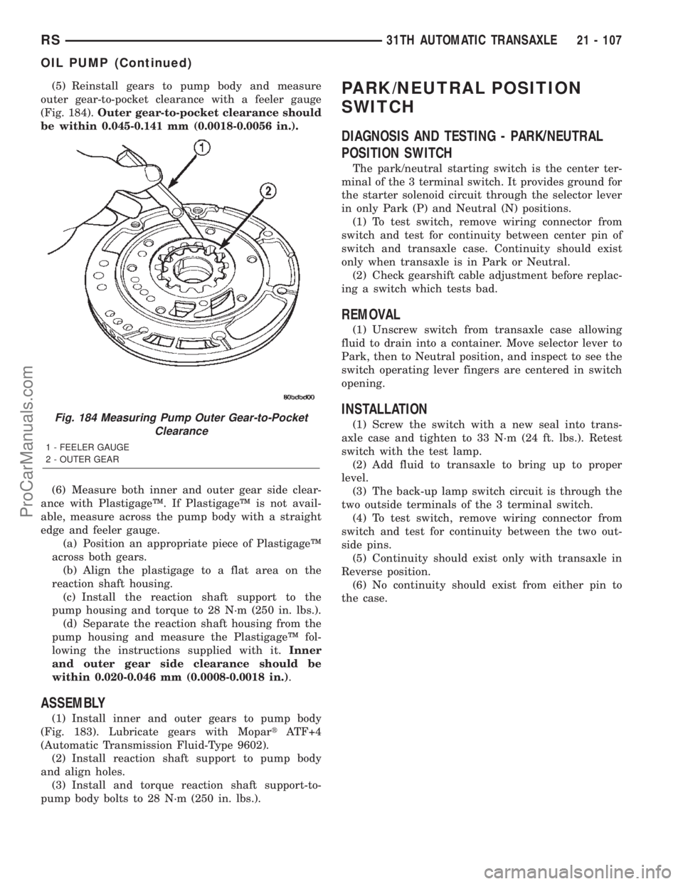
(5) Reinstall gears to pump body and measure
outer gear-to-pocket clearance with a feeler gauge
(Fig. 184).Outer gear-to-pocket clearance should
be within 0.045-0.141 mm (0.0018-0.0056 in.).
(6) Measure both inner and outer gear side clear-
ance with PlastigageŸ. If PlastigageŸ is not avail-
able, measure across the pump body with a straight
edge and feeler gauge.
(a) Position an appropriate piece of PlastigageŸ
across both gears.
(b) Align the plastigage to a flat area on the
reaction shaft housing.
(c) Install the reaction shaft support to the
pump housing and torque to 28 N´m (250 in. lbs.).
(d) Separate the reaction shaft housing from the
pump housing and measure the PlastigageŸ fol-
lowing the instructions supplied with it.Inner
and outer gear side clearance should be
within 0.020-0.046 mm (0.0008-0.0018 in.).
ASSEMBLY
(1) Install inner and outer gears to pump body
(Fig. 183). Lubricate gears with MopartATF+4
(Automatic Transmission Fluid-Type 9602).
(2) Install reaction shaft support to pump body
and align holes.
(3) Install and torque reaction shaft support-to-
pump body bolts to 28 N´m (250 in. lbs.).
PARK/NEUTRAL POSITION
SWITCH
DIAGNOSIS AND TESTING - PARK/NEUTRAL
POSITION SWITCH
The park/neutral starting switch is the center ter-
minal of the 3 terminal switch. It provides ground for
the starter solenoid circuit through the selector lever
in only Park (P) and Neutral (N) positions.
(1) To test switch, remove wiring connector from
switch and test for continuity between center pin of
switch and transaxle case. Continuity should exist
only when transaxle is in Park or Neutral.
(2) Check gearshift cable adjustment before replac-
ing a switch which tests bad.
REMOVAL
(1) Unscrew switch from transaxle case allowing
fluid to drain into a container. Move selector lever to
Park, then to Neutral position, and inspect to see the
switch operating lever fingers are centered in switch
opening.
INSTALLATION
(1) Screw the switch with a new seal into trans-
axle case and tighten to 33 N´m (24 ft. lbs.). Retest
switch with the test lamp.
(2) Add fluid to transaxle to bring up to proper
level.
(3) The back-up lamp switch circuit is through the
two outside terminals of the 3 terminal switch.
(4) To test switch, remove wiring connector from
switch and test for continuity between the two out-
side pins.
(5) Continuity should exist only with transaxle in
Reverse position.
(6) No continuity should exist from either pin to
the case.Fig. 184 Measuring Pump Outer Gear-to-Pocket
Clearance
1 - FEELER GAUGE
2 - OUTER GEAR
RS31TH AUTOMATIC TRANSAXLE21 - 107
OIL PUMP (Continued)
ProCarManuals.com
Page 1676 of 2399
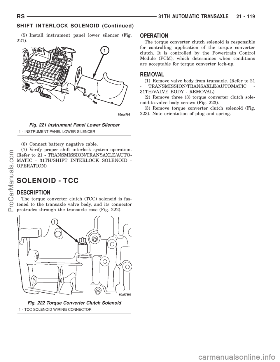
(5) Install instrument panel lower silencer (Fig.
221).
(6) Connect battery negative cable.
(7) Verify proper shift interlock system operation.
(Refer to 21 - TRANSMISSION/TRANSAXLE/AUTO-
MATIC - 31TH/SHIFT INTERLOCK SOLENOID -
OPERATION)
SOLENOID - TCC
DESCRIPTION
The torque converter clutch (TCC) solenoid is fas-
tened to the transaxle valve body, and its connector
protrudes through the transaxle case (Fig. 222).
OPERATION
The torque converter clutch solenoid is responsible
for controlling application of the torque converter
clutch. It is controlled by the Powertrain Control
Module (PCM), which determines when conditions
are acceptable for torque converter lock-up.
REMOVAL
(1) Remove valve body from transaxle. (Refer to 21
- TRANSMISSION/TRANSAXLE/AUTOMATIC -
31TH/VALVE BODY - REMOVAL)
(2) Remove three (3) torque converter clutch sole-
noid-to-valve body screws (Fig. 223).
(3) Remove torque converter clutch solenoid (Fig.
223). Note orientation of plug and spring.
Fig. 221 Instrument Panel Lower Silencer
1 - INSTRUMENT PANEL LOWER SILENCER
Fig. 222 Torque Converter Clutch Solenoid
1 - TCC SOLENOID WIRING CONNECTOR
RS31TH AUTOMATIC TRANSAXLE21 - 119
SHIFT INTERLOCK SOLENOID (Continued)
ProCarManuals.com