2002 CHRYSLER CARAVAN fuel
[x] Cancel search: fuelPage 2368 of 2399
nation by this diagnostic. When the vacuum in the
system exceeds about 19H2O (0.25 KPA), a vacuum
switch closes. The switch closure sends a signal to
the NGC. The NGC, via appropriate logic strategies
(described below), utilizes the switch signal, or lack
thereof, to make a determination of whether a leak is
present.
The NVLD device is designed with a normally open
vacuum switch, a normally closed solenoid, and a
seal, which is actuated by both the solenoid and a
diaphragm. The NVLD is located on the atmospheric
vent side of the canister. The NVLD assembly may
be mounted on top of the canister outlet, or in-line
between the canister and atmospheric vent filter. The
normally open vacuum switch will close with about 19
H2O (0.25 KPA) vacuum in the evaporative system.
The diaphragm actuates the switch. This is above the
opening point of the fuel inlet check valve in the fill
tube so cap off leaks can be detected. Submerged fill
systems must have recirculation lines that do not
have the in-line normally closed check valve that pro-
tects the system from failed nozzle liquid ingestion,
in order to detect cap off conditions.
The normally closed valve in the NVLD is intended
to maintain the seal on the evaporative system dur-
ing the engine off condition. If vacuum in the evapo-
rative system exceeds 39to 69H2O (0.75 to 1.5 KPA),
the valve will be pulled off the seat, opening the seal.
This will protect the system from excessive vacuum
as well as allowing sufficient purge flow in the event
that the solenoid was to become inoperative.
The solenoid actuates the valve to unseal the can-
ister vent while the engine is running. It also will be
used to close the vent during the medium and large
leak tests and during the purge flow check. This sole-
noid requires initial 1.5 amps of current to pull the
valve open but after 100 ms. will be duty cycled down
to an average of about 150 mA for the remainder of
the drive cycle.
Another feature in the device is a diaphragm that
will open the seal in the NVLD with pressure in the
evaporative system. The device will9blow off9at
about 0.59H2O (0.12 KPA) pressure to permit the
venting of vapors during refueling. An added benefit
to this is that it will also allow the tank to9breathe9
during increasing temperatures, thus limiting the
pressure in the tank to this low level. This is benefi-
cial because the induced vacuum during a subse-
quent declining temperature will achieve the switch
closed (pass threshold) sooner than if the tank had to
decay from a built up pressure.
The device itself has 3 wires: Switch sense, sole-
noid driver and ground. It also includes a resistor to
protect the switch from a short to battery or a short
to ground. The NGC utilizes a high-side driver to
energize and duty-cycle the solenoid.DESCRIPTION - HIGH AND LOW LIMITS
The PCM compares input signal voltages from each
input device with established high and low limits for
the device. If the input voltage is not within limits
and other criteria are met, the PCM stores a diagnos-
tic trouble code in memory. Other diagnostic trouble
code criteria might include engine RPM limits or
input voltages from other sensors or switches that
must be present before verifying a diagnostic trouble
code condition.
OPERATION
OPERATION - SYSTEM
The Powertrain Control Module (PCM) monitors
many different circuits in the fuel injection, ignition,
emission and engine systems. If the PCM senses a
problem with a monitored circuit often enough to
indicate an actual problem, it stores a Diagnostic
Trouble Code (DTC) in the PCM's memory. If the
code applies to a non-emissions related component or
system, and the problem is repaired or ceases to
exist, the PCM cancels the code after 40 warmup
cycles. Diagnostic trouble codes that affect vehicle
emissions illuminate the Malfunction Indicator Lamp
(MIL). Refer to Malfunction Indicator Lamp in this
section.
Certain criteria must be met before the PCM
stores a DTC in memory. The criteria may be a spe-
cific range of engine RPM, engine temperature,
and/or input voltage to the PCM.
The PCM might not store a DTC for a monitored
circuit even though a malfunction has occurred. This
may happen because one of the DTC criteria for the
circuit has not been met.For example, assume the
diagnostic trouble code criteria requires the PCM to
monitor the circuit only when the engine operates
between 750 and 2000 RPM. Suppose the sensor's
output circuit shorts to ground when engine operates
above 2400 RPM (resulting in 0 volt input to the
PCM). Because the condition happens at an engine
speed above the maximum threshold (2000 rpm), the
PCM will not store a DTC.
There are several operating conditions for which
the PCM monitors and sets DTC's. Refer to Moni-
tored Systems, Components, and Non-Monitored Cir-
cuits in this section.
NOTE: Various diagnostic procedures may actually
cause a diagnostic monitor to set a DTC. For
instance, pulling a spark plug wire to perform a
spark test may set the misfire code. When a repair
is completed and verified, use the DRBIIITscan tool
to erase all DTC's and extinguish the MIL.
RSEMISSIONS CONTROL25-9
EMISSIONS CONTROL (Continued)
ProCarManuals.com
Page 2370 of 2399
EVAPORATIVE EMISSIONS
TABLE OF CONTENTS
page page
EVAPORATIVE EMISSIONS
OPERATION - EVAPORATION CONTROL
SYSTEM............................11
SPECIFICATIONS
TORQUE............................12
EVAP/PURGE SOLENOID
DESCRIPTION.........................13
OPERATION...........................13
REMOVAL.............................13
INSTALLATION.........................13
FUEL FILLER CAP
DESCRIPTION.........................13
OPERATION...........................13
LEAK DETECTION PUMP
REMOVAL.............................14
INSTALLATION.........................14
ORVR
OPERATION...........................14DIAGNOSIS AND TESTING - VEHICLE DOES
NOT FILL............................16
P C V VA LV E
DESCRIPTION.........................17
OPERATION...........................17
DIAGNOSIS AND TESTING - PCV SYSTEM . . . 17
VAPOR CANISTER
DESCRIPTION.........................18
OPERATION...........................18
REMOVAL
REMOVAL...........................19
REMOVAL - REAR EVAP CANISTER.......19
INSTALLATION
INSTALLATION.......................19
INSTALLATION - REAR EVAP CANISTER . . . 19
EVAPORATIVE EMISSIONS
OPERATION - EVAPORATION CONTROL
SYSTEM
The evaporation control system prevents the emis-
sion of fuel tank vapors into the atmosphere. When
fuel evaporates in the fuel tank, the vapors pass
through vent hoses or tubes to an activated carbon
filled evaporative canister. The canister temporarily
holds the vapors. The Powertrain Control Module
(PCM) allows intake manifold vacuum to draw
vapors into the combustion chambers during certain
operating conditions (Fig. 1).All engines use a proportional purge solenoid sys-
tem. The PCM controls vapor flow by operating the
purge solenoid. Refer to Proportional Purge Solenoid
in this section.
NOTE: The evaporative system uses specially man-
ufactured hoses. If they need replacement, only use
fuel resistant hose. Also the hoses must be able to
pass an Ozone compliance test.
NOTE: For more information on Onboard Refueling
Vapor Recovery (ORVR), refer to the Fuel Delivery
section.
RSEVAPORATIVE EMISSIONS25-11
ProCarManuals.com
Page 2371 of 2399
SPECIFICATIONS
TORQUE
DESCRIPTION N´m Ft. Lbs. In. Lbs.
PCV VAlve 3.3/3.8L 6.3 55
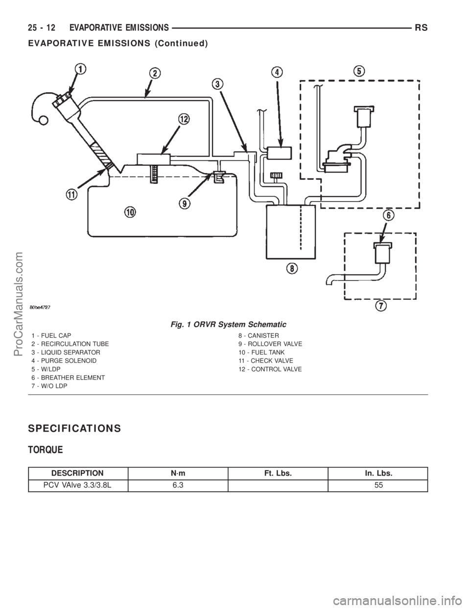
Fig. 1 ORVR System Schematic
1 - FUEL CAP
2 - RECIRCULATION TUBE
3 - LIQUID SEPARATOR
4 - PURGE SOLENOID
5 - W/LDP
6 - BREATHER ELEMENT
7 - W/O LDP8 - CANISTER
9 - ROLLOVER VALVE
10 - FUEL TANK
11 - CHECK VALVE
12 - CONTROL VALVE
25 - 12 EVAPORATIVE EMISSIONSRS
EVAPORATIVE EMISSIONS (Continued)
ProCarManuals.com
Page 2372 of 2399
EVAP/PURGE SOLENOID
DESCRIPTION
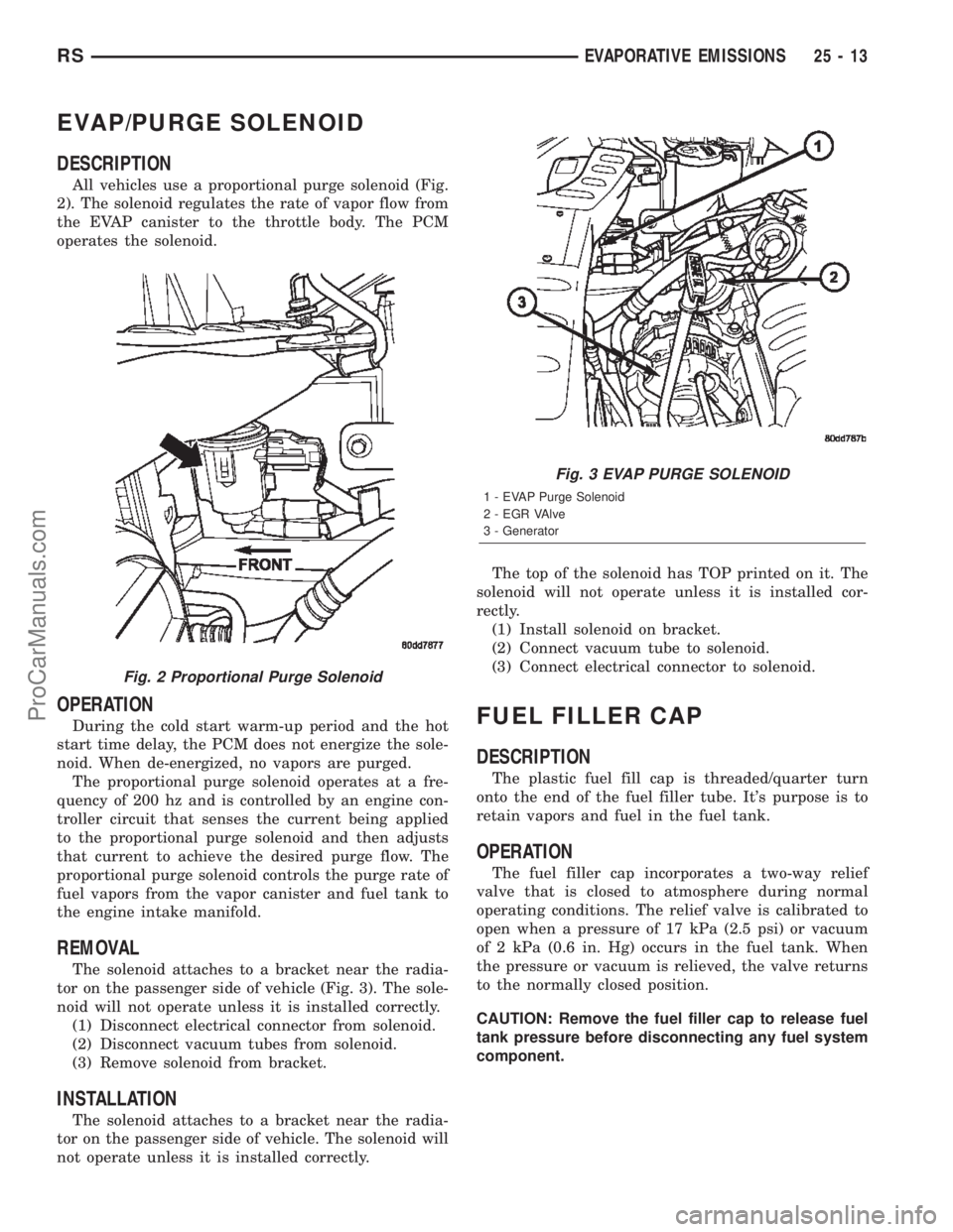
All vehicles use a proportional purge solenoid (Fig.
2). The solenoid regulates the rate of vapor flow from
the EVAP canister to the throttle body. The PCM
operates the solenoid.
OPERATION
During the cold start warm-up period and the hot
start time delay, the PCM does not energize the sole-
noid. When de-energized, no vapors are purged.
The proportional purge solenoid operates at a fre-
quency of 200 hz and is controlled by an engine con-
troller circuit that senses the current being applied
to the proportional purge solenoid and then adjusts
that current to achieve the desired purge flow. The
proportional purge solenoid controls the purge rate of
fuel vapors from the vapor canister and fuel tank to
the engine intake manifold.
REMOVAL
The solenoid attaches to a bracket near the radia-
tor on the passenger side of vehicle (Fig. 3). The sole-
noid will not operate unless it is installed correctly.
(1) Disconnect electrical connector from solenoid.
(2) Disconnect vacuum tubes from solenoid.
(3) Remove solenoid from bracket.
INSTALLATION
The solenoid attaches to a bracket near the radia-
tor on the passenger side of vehicle. The solenoid will
not operate unless it is installed correctly.The top of the solenoid has TOP printed on it. The
solenoid will not operate unless it is installed cor-
rectly.
(1) Install solenoid on bracket.
(2) Connect vacuum tube to solenoid.
(3) Connect electrical connector to solenoid.
FUEL FILLER CAP
DESCRIPTION
The plastic fuel fill cap is threaded/quarter turn
onto the end of the fuel filler tube. It's purpose is to
retain vapors and fuel in the fuel tank.
OPERATION
The fuel filler cap incorporates a two-way relief
valve that is closed to atmosphere during normal
operating conditions. The relief valve is calibrated to
open when a pressure of 17 kPa (2.5 psi) or vacuum
of 2 kPa (0.6 in. Hg) occurs in the fuel tank. When
the pressure or vacuum is relieved, the valve returns
to the normally closed position.
CAUTION: Remove the fuel filler cap to release fuel
tank pressure before disconnecting any fuel system
component.
Fig. 2 Proportional Purge Solenoid
Fig. 3 EVAP PURGE SOLENOID
1 - EVAP Purge Solenoid
2 - EGR VAlve
3 - Generator
RSEVAPORATIVE EMISSIONS25-13
ProCarManuals.com
Page 2373 of 2399
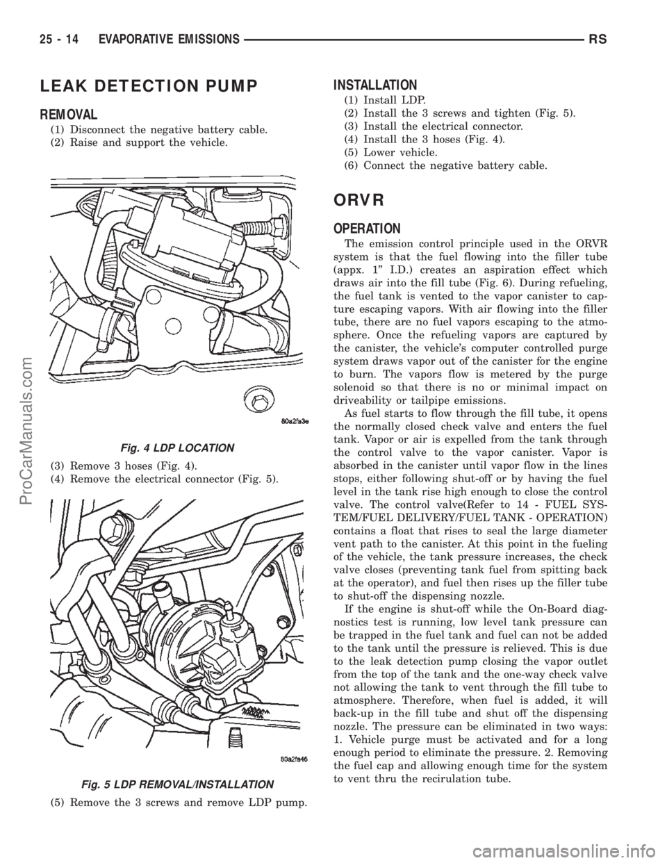
LEAK DETECTION PUMP
REMOVAL
(1) Disconnect the negative battery cable.
(2) Raise and support the vehicle.
(3) Remove 3 hoses (Fig. 4).
(4) Remove the electrical connector (Fig. 5).
(5) Remove the 3 screws and remove LDP pump.
INSTALLATION
(1) Install LDP.
(2) Install the 3 screws and tighten (Fig. 5).
(3) Install the electrical connector.
(4) Install the 3 hoses (Fig. 4).
(5) Lower vehicle.
(6) Connect the negative battery cable.
ORVR
OPERATION
The emission control principle used in the ORVR
system is that the fuel flowing into the filler tube
(appx. 1º I.D.) creates an aspiration effect which
draws air into the fill tube (Fig. 6). During refueling,
the fuel tank is vented to the vapor canister to cap-
ture escaping vapors. With air flowing into the filler
tube, there are no fuel vapors escaping to the atmo-
sphere. Once the refueling vapors are captured by
the canister, the vehicle's computer controlled purge
system draws vapor out of the canister for the engine
to burn. The vapors flow is metered by the purge
solenoid so that there is no or minimal impact on
driveability or tailpipe emissions.
As fuel starts to flow through the fill tube, it opens
the normally closed check valve and enters the fuel
tank. Vapor or air is expelled from the tank through
the control valve to the vapor canister. Vapor is
absorbed in the canister until vapor flow in the lines
stops, either following shut-off or by having the fuel
level in the tank rise high enough to close the control
valve. The control valve(Refer to 14 - FUEL SYS-
TEM/FUEL DELIVERY/FUEL TANK - OPERATION)
contains a float that rises to seal the large diameter
vent path to the canister. At this point in the fueling
of the vehicle, the tank pressure increases, the check
valve closes (preventing tank fuel from spitting back
at the operator), and fuel then rises up the filler tube
to shut-off the dispensing nozzle.
If the engine is shut-off while the On-Board diag-
nostics test is running, low level tank pressure can
be trapped in the fuel tank and fuel can not be added
to the tank until the pressure is relieved. This is due
to the leak detection pump closing the vapor outlet
from the top of the tank and the one-way check valve
not allowing the tank to vent through the fill tube to
atmosphere. Therefore, when fuel is added, it will
back-up in the fill tube and shut off the dispensing
nozzle. The pressure can be eliminated in two ways:
1. Vehicle purge must be activated and for a long
enough period to eliminate the pressure. 2. Removing
the fuel cap and allowing enough time for the system
to vent thru the recirulation tube.
Fig. 4 LDP LOCATION
Fig. 5 LDP REMOVAL/INSTALLATION
25 - 14 EVAPORATIVE EMISSIONSRS
ProCarManuals.com
Page 2374 of 2399
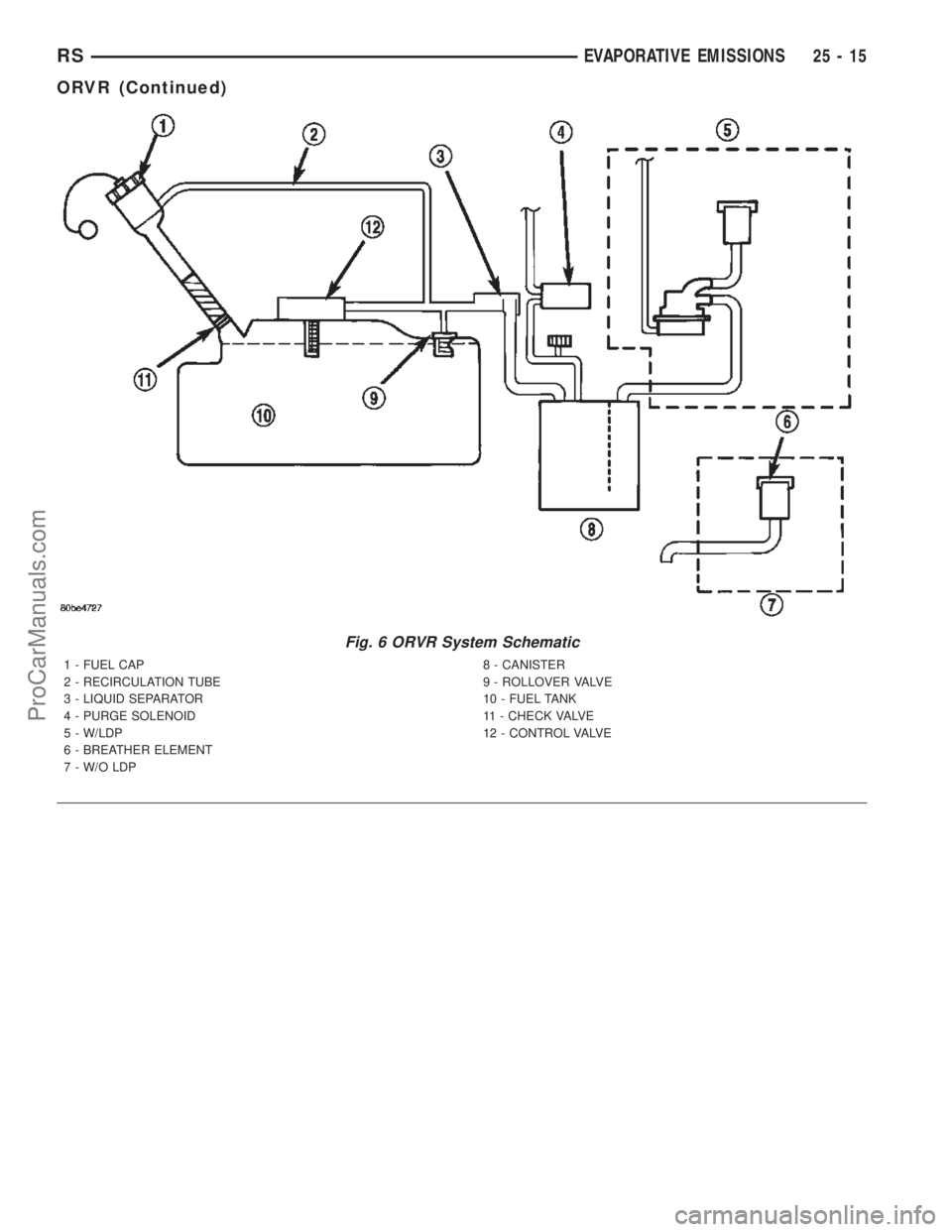
Fig. 6 ORVR System Schematic
1 - FUEL CAP
2 - RECIRCULATION TUBE
3 - LIQUID SEPARATOR
4 - PURGE SOLENOID
5 - W/LDP
6 - BREATHER ELEMENT
7 - W/O LDP8 - CANISTER
9 - ROLLOVER VALVE
10 - FUEL TANK
11 - CHECK VALVE
12 - CONTROL VALVE
RSEVAPORATIVE EMISSIONS25-15
ORVR (Continued)
ProCarManuals.com
Page 2375 of 2399
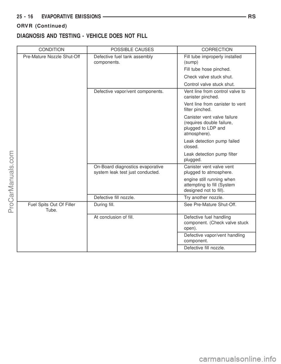
DIAGNOSIS AND TESTING - VEHICLE DOES NOT FILL
CONDITION POSSIBLE CAUSES CORRECTION
Pre-Mature Nozzle Shut-Off Defective fuel tank assembly
components.Fill tube improperly installed
(sump)
Fill tube hose pinched.
Check valve stuck shut.
Control valve stuck shut.
Defective vapor/vent components. Vent line from control valve to
canister pinched.
Vent line from canister to vent
filter pinched.
Canister vent valve failure
(requires double failure,
plugged to LDP and
atmosphere).
Leak detection pump failed
closed.
Leak detection pump filter
plugged.
On-Board diagnostics evaporative
system leak test just conducted.Canister vent valve vent
plugged to atmosphere.
engine still running when
attempting to fill (System
designed not to fill).
Defective fill nozzle. Try another nozzle.
Fuel Spits Out Of Filler
Tube.During fill. See Pre-Mature Shut-Off.
At conclusion of fill. Defective fuel handling
component. (Check valve stuck
open).
Defective vapor/vent handling
component.
Defective fill nozzle.
25 - 16 EVAPORATIVE EMISSIONSRS
ORVR (Continued)
ProCarManuals.com
Page 2377 of 2399
noise will be heard as air passes through the valve. A
strong vacuum should also be felt when a finger is
placed over the valve inlet.
(2) Install hose on PCV valve. Remove the
make-up air hose from the air plenum at the rear of
the engine. Hold a piece of stiff paper (parts tag)
loosely over the end of the make-up air hose.
(3) After allowing approximately one minute for
crankcase pressure to reduce, the paper should draw
up against the hose with noticeable force. If the
engine does not draw the paper against the grommet
after installing a new valve, replace the PCV valve
hose.
(4) Turn the engine off. Remove the PCV valve
from intake manifold. The valve should rattle when
shaken.
(5) Replace the PCV valve and retest the system if
it does not operate as described in the preceding
tests.Do not attempt to clean the old PCV valve.
If the valve rattles, apply a light coating of Loctitet
Pipe Sealant With Teflon to the threads. Thread the
PCV valve into the manifold plenum and tighten to 7
N´m (60 in. lbs.) torque.
VAPOR CANISTER
DESCRIPTION
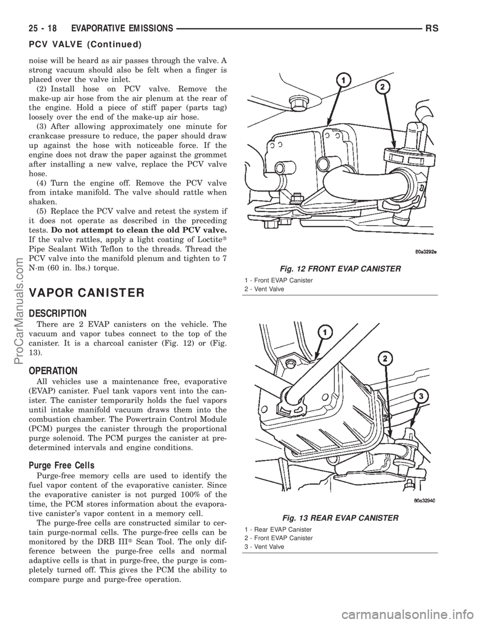
There are 2 EVAP canisters on the vehicle. The
vacuum and vapor tubes connect to the top of the
canister. It is a charcoal canister (Fig. 12) or (Fig.
13).
OPERATION
All vehicles use a maintenance free, evaporative
(EVAP) canister. Fuel tank vapors vent into the can-
ister. The canister temporarily holds the fuel vapors
until intake manifold vacuum draws them into the
combustion chamber. The Powertrain Control Module
(PCM) purges the canister through the proportional
purge solenoid. The PCM purges the canister at pre-
determined intervals and engine conditions.
Purge Free Cells
Purge-free memory cells are used to identify the
fuel vapor content of the evaporative canister. Since
the evaporative canister is not purged 100% of the
time, the PCM stores information about the evapora-
tive canister's vapor content in a memory cell.
The purge-free cells are constructed similar to cer-
tain purge-normal cells. The purge-free cells can be
monitored by the DRB IIItScan Tool. The only dif-
ference between the purge-free cells and normal
adaptive cells is that in purge-free, the purge is com-
pletely turned off. This gives the PCM the ability to
compare purge and purge-free operation.
Fig. 12 FRONT EVAP CANISTER
1 - Front EVAP Canister
2 - Vent Valve
Fig. 13 REAR EVAP CANISTER
1 - Rear EVAP Canister
2 - Front EVAP Canister
3 - Vent Valve
25 - 18 EVAPORATIVE EMISSIONSRS
PCV VALVE (Continued)
ProCarManuals.com