2002 CHRYSLER CARAVAN fuel
[x] Cancel search: fuelPage 1842 of 2399
TORQUE CONVERTER
DESCRIPTION
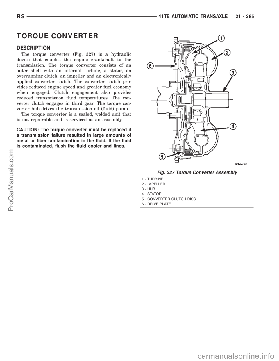
The torque converter (Fig. 327) is a hydraulic
device that couples the engine crankshaft to the
transmission. The torque converter consists of an
outer shell with an internal turbine, a stator, an
overrunning clutch, an impeller and an electronically
applied converter clutch. The converter clutch pro-
vides reduced engine speed and greater fuel economy
when engaged. Clutch engagement also provides
reduced transmission fluid temperatures. The con-
verter clutch engages in third gear. The torque con-
verter hub drives the transmission oil (fluid) pump.
The torque converter is a sealed, welded unit that
is not repairable and is serviced as an assembly.
CAUTION: The torque converter must be replaced if
a transmission failure resulted in large amounts of
metal or fiber contamination in the fluid. If the fluid
is contaminated, flush the fluid cooler and lines.
Fig. 327 Torque Converter Assembly
1 - TURBINE
2 - IMPELLER
3 - HUB
4-STATOR
5 - CONVERTER CLUTCH DISC
6 - DRIVE PLATE
RS41TE AUTOMATIC TRANSAXLE21 - 285
ProCarManuals.com
Page 1850 of 2399
is requested when the TCM pulses this signal to
ground. The PCM recognizes this request and
responds by retarding ignition timing, killing fuel
injectors, etc. The PCM sends a confirmation of the
request to the TCM via the communication bus.
Torque reduction is not noticable by the driver, and
usually lasts for a very short period of time.
If the confirmation signal is not received by the
TCM after two sequential request messages, a diag-
nostic trouble code will be set.
VALVE BODY
DESCRIPTION
The valve body assembly consists of a cast alumi-
num valve body, a separator plate, and transfer
plate. The valve body contains valves and check balls
that control fluid delivery to the torque converter
clutch, solenoid/pressure switch assembly, and fric-
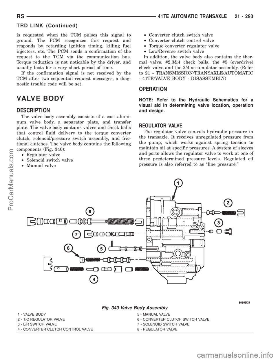
tional clutches. The valve body contains the following
components (Fig. 340):
²Regulator valve
²Solenoid switch valve
²Manual valve²Converter clutch switch valve
²Converter clutch control valve
²Torque converter regulator valve
²Low/Reverse switch valve
In addition, the valve body also contains the ther-
mal valve, #2,3&4 check balls, the #5 (overdrive)
check valve and the 2/4 accumulator assembly. (Refer
to 21 - TRANSMISSION/TRANSAXLE/AUTOMATIC
- 41TE/VALVE BODY - DISASSEMBLY)
OPERATION
NOTE: Refer to the Hydraulic Schematics for a
visual aid in determining valve location, operation
and design.
REGULATOR VALVE
The regulator valve controls hydraulic pressure in
the transaxle. It receives unregulated pressure from
the pump, which works against spring tension to
maintain oil at specific pressures. A system of sleeves
and ports allows the regulator valve to work at one of
three predetermined pressure levels. Regulated oil
pressure is also referred to as ªline pressure.º
Fig. 340 Valve Body Assembly
1 - VALVE BODY 5 - MANUAL VALVE
2 - T/C REGULATOR VALVE 6 - CONVERTER CLUTCH SWITCH VALVE
3 - L/R SWITCH VALVE 7 - SOLENOID SWITCH VALVE
4 - CONVERTER CLUTCH CONTROL VALVE 8 - REGULATOR VALVE
RS41TE AUTOMATIC TRANSAXLE21 - 293
TRD LINK (Continued)
ProCarManuals.com
Page 1977 of 2399
door temperature drops. After checking the air
pressure, replace valve cap finger tight.
Inflation pressures specified on the Tire Inflation
Pressure Label are always the cold inflation pressure
of the tire. Cold inflation pressure is obtained after
the vehicle has not been operated for at least 3
hours, or the vehicle is driven less than one mile
after being inoperative for 3 hours. Tire inflation
pressures may increase from 2 to 6 pounds persquare inch (psi) (14 to 41 kPa) during operation. Do
not reduce this normal pressure buildup.
Improper inflation can cause:
²Uneven wear patterns
²Reduced tread life
²Reduced fuel economy
²Unsatisfactory ride
²The vehicle to drift.
WARNING: OVER OR UNDER INFLATED TIRES CAN
AFFECT VEHICLE HANDLING. THE TIRE CAN FAIL
SUDDENLY, RESULTING IN LOSS OF VEHICLE
CONTROL.
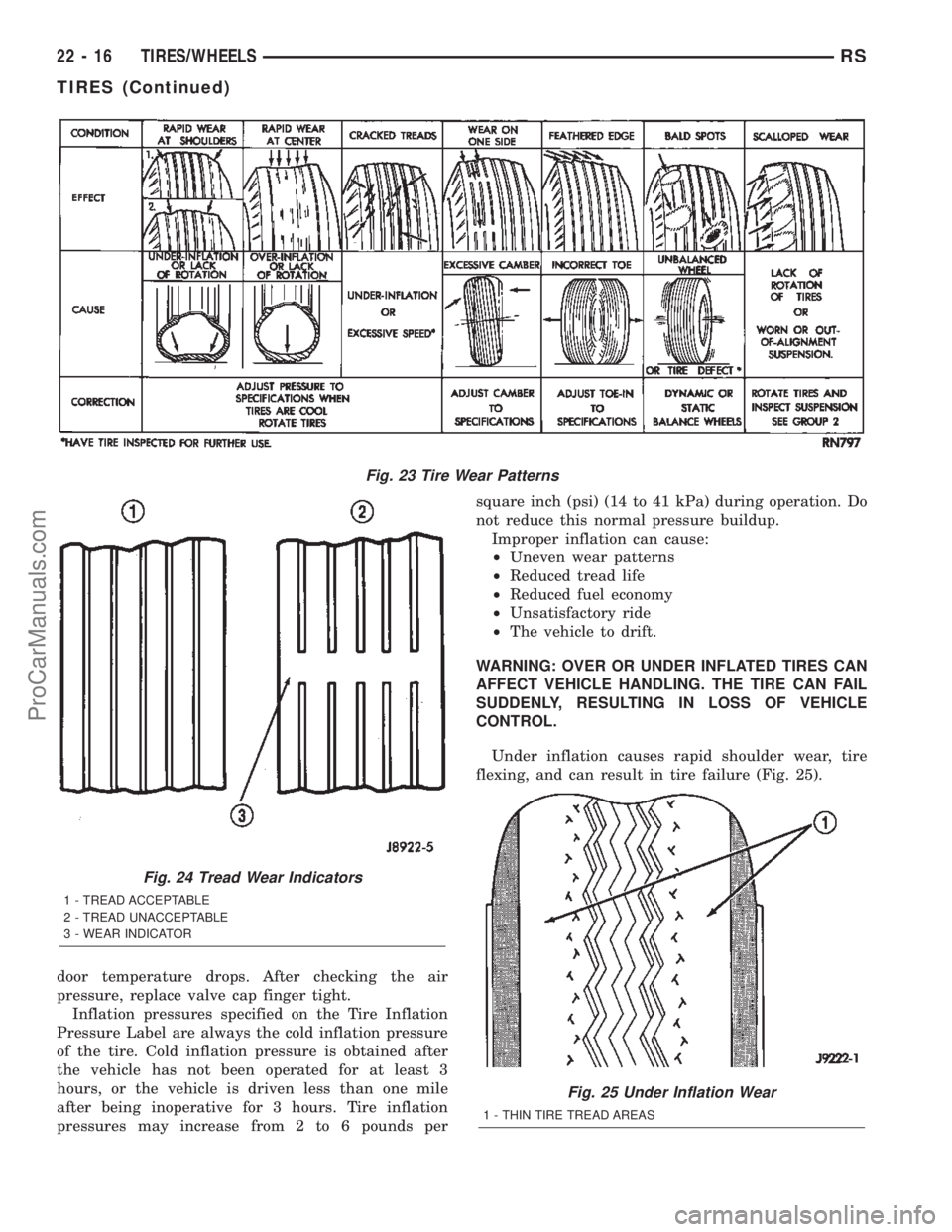
Under inflation causes rapid shoulder wear, tire
flexing, and can result in tire failure (Fig. 25).
Fig. 23 Tire Wear Patterns
Fig. 24 Tread Wear Indicators
1 - TREAD ACCEPTABLE
2 - TREAD UNACCEPTABLE
3 - WEAR INDICATOR
Fig. 25 Under Inflation Wear
1 - THIN TIRE TREAD AREAS
22 - 16 TIRES/WHEELSRS
TIRES (Continued)
ProCarManuals.com
Page 1996 of 2399
MOPARTSPRAY WHITE LUBE OR EQUIVALENT
²Door Check Straps
²Liftgate Latches
²Liftgate Prop Pivots
²Ash Receiver
²Fuel Filler Door Remote Control Latch Mecha-
nism
²Parking Brake Mechanism
²Sliding Seat Tracks
²Liftgate Latch
MOPARTMultipurpose GREASE OR EQUIVALENT
²All Other Hood Mechanisms
MOPARTLOCK CYLINDER LUBRICANT OR
EQUIVALENT
²Door Lock Cylinders
²Liftgate Lock Cylinder
SPECIAL TOOLS
BODY
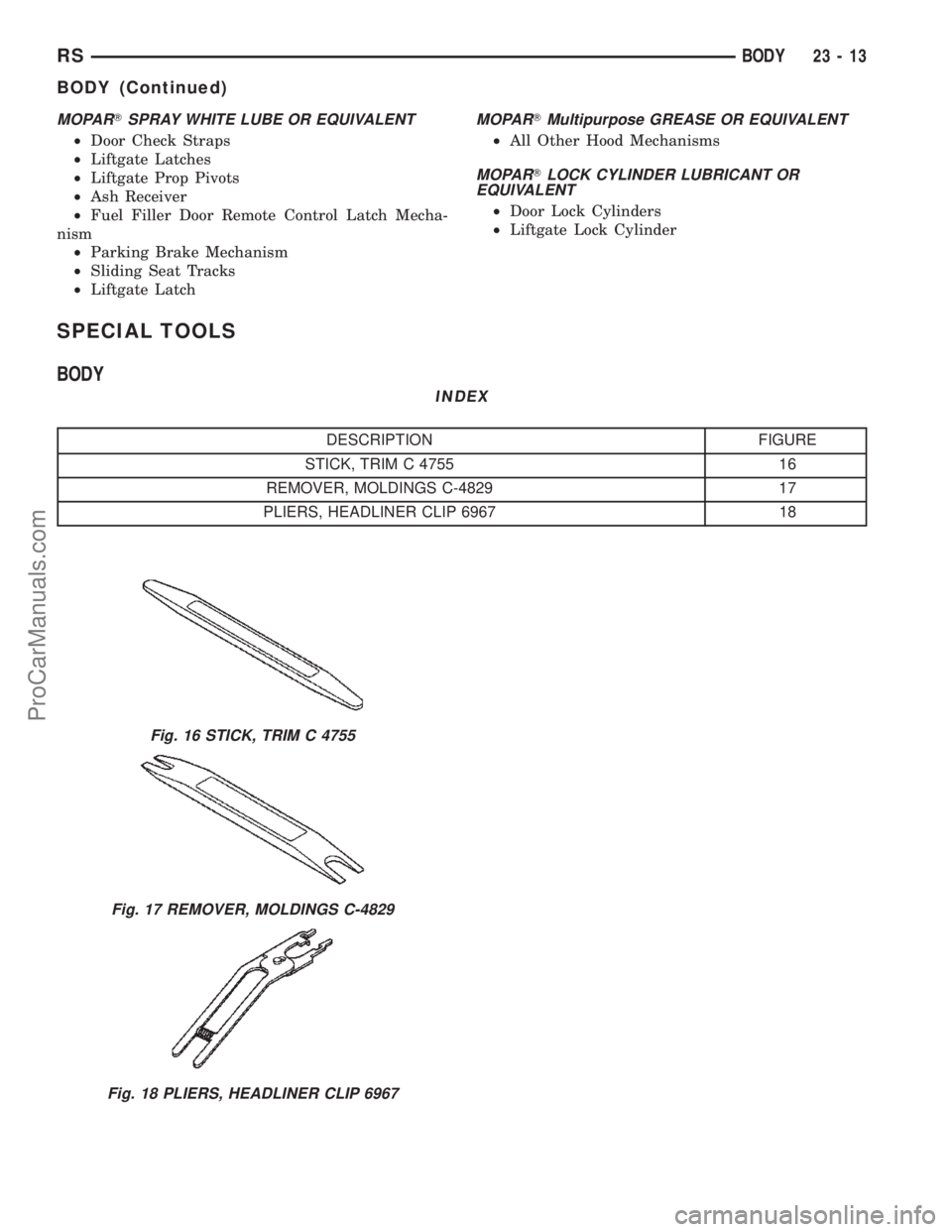
INDEX
DESCRIPTION FIGURE
STICK, TRIM C 4755 16
REMOVER, MOLDINGS C-4829 17
PLIERS, HEADLINER CLIP 6967 18
Fig. 16 STICK, TRIM C 4755
Fig. 17 REMOVER, MOLDINGS C-4829
Fig. 18 PLIERS, HEADLINER CLIP 6967
RSBODY23-13
BODY (Continued)
ProCarManuals.com
Page 2013 of 2399
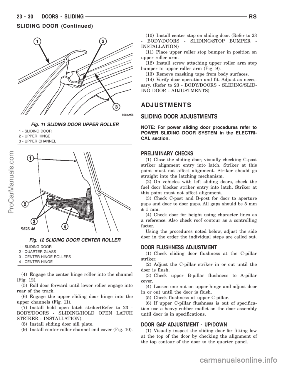
(4) Engage the center hinge roller into the channel
(Fig. 12).
(5) Roll door forward until lower roller engage into
rear of the track.
(6) Engage the upper sliding door hinge into the
upper channels (Fig. 11).
(7) Install hold open latch striker(Refer to 23 -
BODY/DOORS - SLIDING/HOLD OPEN LATCH
STRIKER - INSTALLATION).
(8) Install sliding door sill plate.
(9) Install center roller channel end cover (Fig. 10).(10) Install center stop on sliding door. (Refer to 23
- BODY/DOORS - SLIDING/STOP BUMPER -
INSTALLATION)
(11) Place upper roller stop bumper in position on
upper roller arm.
(12) Install screw attaching upper roller arm stop
bumper to upper roller arm (Fig. 9).
(13) Remove masking tape from body surfaces.
(14) Verify door operation and fit. Adjust as neces-
sary. (Refer to 23 - BODY/DOORS - SLIDING/SLID-
ING DOOR - ADJUSTMENTS)
ADJUSTMENTS
SLIDING DOOR ADJUSTMENTS
NOTE: For power sliding door procedures refer to
POWER SLIDING DOOR SYSTEM in the ELECTRI-
CAL section.
PRELIMINARY CHECKS
(1) Close the sliding door, visually checking C-post
striker alignment entry into latch. Striker at this
point must not affect alignment. Striker should go
straight into the latching mechanism.
(2) On vehicles with left sliding doors, check the
fuel door blocker striker entry into latch. Striker at
this point must not affect alignment.
(3) Check C-post and B-post for door to aperture
gaps and door to door gaps. All gaps should be 5 mm
1 mm.
(4) Check door for height using character lines as
a reference. Also check roof contour as a controlling
factor.
Using the procedures noted below, adjust the side
door in the order the individual steps are called out.
DOOR FLUSHNESS ADJUSTMENT
(1) Check sliding door flushness at the C-pillar
striker.
(2) Adjust the C-pillar striker in or out until the
door is flush.
(3) Check upper B-pillar flushness to A-pillar
cover.
(4) Loosen one nut on upper hinge and adjust door
in or out until the door is flush.
(5) Check flushness at upper C-pillar.
(6) If upper C-pillar flushness is out of specifica-
tion use a heavy rubber mallet on the door assembly
until door is in specifications.
DOOR GAP ADJUSTMENT - UP/DOWN
(1) Visually inspect the sliding door for fitting low
at the top of the door by checking the alignment of
the top contour of the door to the quarter panel.
Fig. 11 SLIDING DOOR UPPER ROLLER
1 - SLIDING DOOR
2 - UPPER HINGE
3 - UPPER CHANNEL
Fig. 12 SLIDING DOOR CENTER ROLLER
1 - SLIDING DOOR
2 - QUARTER GLASS
3 - CENTER HINGE ROLLERS
4 - CENTER HINGE
23 - 30 DOORS - SLIDINGRS
SLIDING DOOR (Continued)
ProCarManuals.com
Page 2027 of 2399
EXTERIOR
TABLE OF CONTENTS
page page
BODY SIDE MOLDINGS
REMOVAL.............................44
INSTALLATION.........................45
COWL GRILLE
REMOVAL.............................50
INSTALLATION.........................50
EXTERIOR NAME PLATES - TAPE ATTACHED
REMOVAL.............................50
INSTALLATION.........................51
EXTERIOR NAME PLATES - ADHESIVE
ATTACHED
REMOVAL.............................51
INSTALLATION.........................51
FRONT FENDER
REMOVAL.............................51
INSTALLATION.........................51
FUEL FILL DOOR
REMOVAL.............................52
INSTALLATION.........................52
FUEL FILL DOOR BLOCKER LATCH
REMOVAL.............................52
INSTALLATION.........................52
FUEL FILL DOOR BLOCKER LATCH STRIKER
REMOVAL.............................53
INSTALLATION.........................53
FUEL FILL DOOR BLOCKER LOCKOUT LINK
REMOVAL.............................53INSTALLATION.........................54
GRILLE OPENING REINFORCEMENT
REMOVAL.............................54
INSTALLATION.........................54
FRONT WHEELHOUSE SPLASH SHIELD
REMOVAL.............................55
INSTALLATION.........................55
LUGGAGE RACK RISER
REMOVAL.............................55
INSTALLATION.........................56
LUGGAGE RACK CROSSBAR
REMOVAL.............................56
INSTALLATION.........................57
REAR QUARTER PANEL/FENDER AIR
EXHAUSTER
DESCRIPTION.........................57
REMOVAL.............................57
INSTALLATION.........................58
ROOF JOINT MOLDING
REMOVAL.............................58
INSTALLATION.........................58
SIDE VIEW MIRROR
REMOVAL.............................58
INSTALLATION.........................58
SIDE VIEW MIRROR GLASS
REMOVAL.............................59
INSTALLATION.........................59
BODY SIDE MOLDINGS
REMOVAL
Refer to (Fig. 1), (Fig. 2), (Fig. 3), (Fig. 4) or (Fig.
5)for proper location of fasteners holding the molding
to the wheelhouse lip and rocker panels.
(1) Warm the affected stick on molding and body
metal to approximately 38É C (100É F) using a suit-
able heat lamp or heat gun.(2) If equipped, remove pop rivets holding molding
edge to wheelhouse lip.
(3) Pull stick on molding from painted surface.
(4) Remove adhesive tape residue from painted
surface of vehicle. Use a 3M Scotch-BriteŸ Molding
Adhesive and Stripe Removal Disc, or equivalent, to
clean adhesive residue from painted surfaces. These
products are available from automotive paint suppli-
ers. Refer to instructions supplied with the specific
product for proper usage.
23 - 44 EXTERIORRS
ProCarManuals.com
Page 2035 of 2399
FUEL FILL DOOR
REMOVAL
(1) Remove left quarter trim panel.
(2) Remove water shield patch covering access hole
in C-pillar.
(3) Disengage latch release link from clip on fuel
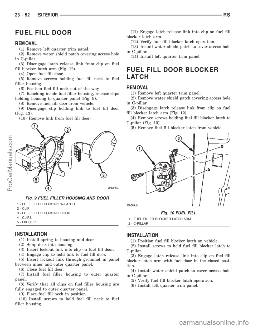
fill blocker latch arm (Fig. 12).
(4) Open fuel fill door.
(5) Remove screws holding fuel fill neck to fuel
filler housing.
(6) Position fuel fill neck out of the way.
(7) Reaching inside fuel filler housing, release clips
holding housing to quarter panel (Fig. 9).
(8) Remove fuel fill door from vehicle.
(9) Disengage clip holding link to fuel fill door
(Fig. 13).
(10) Remove link from fuel fill door.
INSTALLATION
(1) Install spring to housing and door
(2) Snap door into housing.
(3) Insert lockout link into clip on fuel fill door.
(4) Engage clip to hold link to fuel fill door.
(5) Insert lockout link through grommet in panel
between inner and outer quarter panel.
(6) Close fuel fill door.
(7) Install fuel filler housing to outer quarter
panel.
(8) Verify that all clips on fuel filler housing are
fully engaged to outer quarter panel.
(9) Place fuel fill neck in position.
(10) Install screws to hold fuel fill neck to fuel
filler housing.(11) Engage latch release link into clip on fuel fill
blocker latch arm.
(12) Verify fuel fill blocker latch operation.
(13) Install water shield patch to cover access hole
in C-pillar.
(14) Install left quarter trim panel.
FUEL FILL DOOR BLOCKER
LATCH
REMOVAL
(1) Remove left quarter trim panel.
(2) Remove water shield patch covering access hole
in C-pillar.
(3) Disengage latch release link from clip on fuel
fill blocker latch arm (Fig. 12).
(4) Remove screws holding fuel fill blocker latch to
C-pillar (Fig. 10).
(5) Remove fuel fill blocker latch from vehicle.
INSTALLATION
(1) Position fuel fill blocker latch on vehicle.
(2) Install screws to hold fuel fill blocker latch to
C-pillar.
(3) Engage latch release link into clip on fuel fill
blocker latch arm with fuel door in the closed posi-
tion.
(4) Install water shield patch to cover access hole
in C-pillar.
(5) Verify fuel fill blocker latch operation.
(6) Install left quarter trim panel.
Fig. 9 FUEL FILLER HOUSING AND DOOR
1 - FUEL FILLER HOUSING W/LATCH
2 - CLIP
3 - FUEL FILLER HOUSING DOOR
4 - CLIPS
5 - FIX CLIP
Fig. 10 FUEL FILL
1 - FUEL FILLER BLOCKER LATCH ARM
2 - C-PILLAR
23 - 52 EXTERIORRS
ProCarManuals.com
Page 2036 of 2399
FUEL FILL DOOR BLOCKER
LATCH STRIKER
REMOVAL
(1) Remove sliding door trim panel.
(2) Remove sound shield as necessary to access
striker
(3) Remove screws attaching fuel fill door blocker
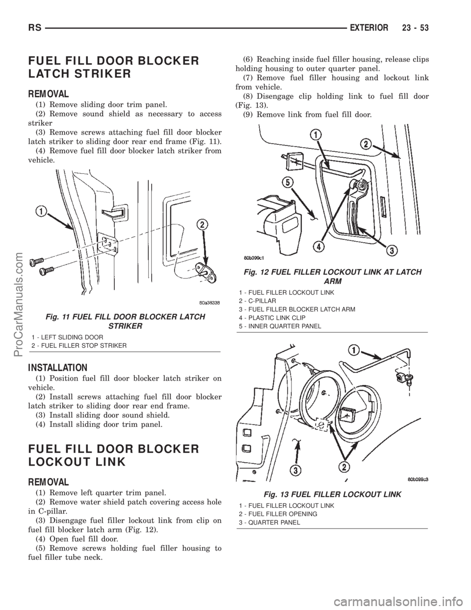
latch striker to sliding door rear end frame (Fig. 11).
(4) Remove fuel fill door blocker latch striker from
vehicle.
INSTALLATION
(1) Position fuel fill door blocker latch striker on
vehicle.
(2) Install screws attaching fuel fill door blocker
latch striker to sliding door rear end frame.
(3) Install sliding door sound shield.
(4) Install sliding door trim panel.
FUEL FILL DOOR BLOCKER
LOCKOUT LINK
REMOVAL
(1) Remove left quarter trim panel.
(2) Remove water shield patch covering access hole
in C-pillar.
(3) Disengage fuel filler lockout link from clip on
fuel fill blocker latch arm (Fig. 12).
(4) Open fuel fill door.
(5) Remove screws holding fuel filler housing to
fuel filler tube neck.(6) Reaching inside fuel filler housing, release clips
holding housing to outer quarter panel.
(7) Remove fuel filler housing and lockout link
from vehicle.
(8) Disengage clip holding link to fuel fill door
(Fig. 13).
(9) Remove link from fuel fill door.
Fig. 11 FUEL FILL DOOR BLOCKER LATCH
STRIKER
1 - LEFT SLIDING DOOR
2 - FUEL FILLER STOP STRIKER
Fig. 12 FUEL FILLER LOCKOUT LINK AT LATCH
ARM
1 - FUEL FILLER LOCKOUT LINK
2 - C-PILLAR
3 - FUEL FILLER BLOCKER LATCH ARM
4 - PLASTIC LINK CLIP
5 - INNER QUARTER PANEL
Fig. 13 FUEL FILLER LOCKOUT LINK
1 - FUEL FILLER LOCKOUT LINK
2 - FUEL FILLER OPENING
3 - QUARTER PANEL
RSEXTERIOR23-53
ProCarManuals.com