2002 CHRYSLER CARAVAN ABS
[x] Cancel search: ABSPage 2062 of 2399
(6) Position quarter trim panel on inner quarter
panel.
(7) Install screws attaching rear edge of quarter
trim to attaching bracket or inner quarter panel.
(8) Install screws attaching quarter trim to inner
quarter panel in bolster area.
(9) Install second row seat belts anchor on long
wheel base vehicle. Tighten all seat belt bolts to 39
N´m (28 in. lbs.) torque.
(10) Install first row seat belt anchor.
(11) Install left D-pillar trim panel.
(12) Install C-pillar trim panel.
(13) Install upper left B-pillar trim on three door
vehicle.
(14) Install left quarter trim bolster.
(15) Install front door sill plate on three door vehi-
cle.
(16) Install sliding door sill plate on four door
vehicle.
(17) Install second row seat, if equipped.
(18) Install first row seat.
(19) Connect the battery negative cable.
REAR HEADER TRIM
REMOVAL
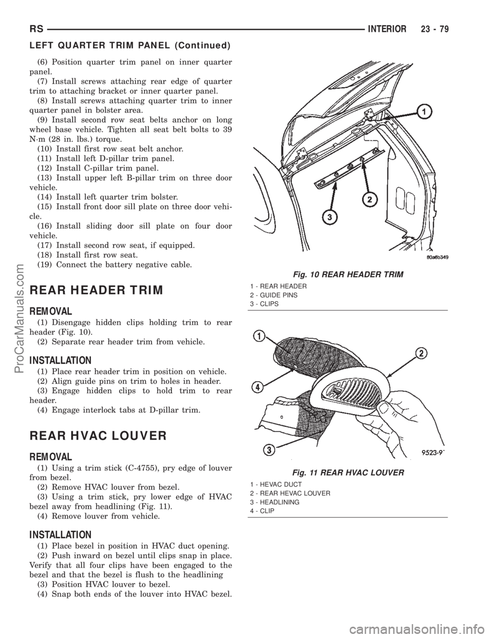
(1) Disengage hidden clips holding trim to rear
header (Fig. 10).
(2) Separate rear header trim from vehicle.
INSTALLATION
(1) Place rear header trim in position on vehicle.
(2) Align guide pins on trim to holes in header.
(3) Engage hidden clips to hold trim to rear
header.
(4) Engage interlock tabs at D-pillar trim.
REAR HVAC LOUVER
REMOVAL
(1) Using a trim stick (C-4755), pry edge of louver
from bezel.
(2) Remove HVAC louver from bezel.
(3) Using a trim stick, pry lower edge of HVAC
bezel away from headlining (Fig. 11).
(4) Remove louver from vehicle.
INSTALLATION
(1) Place bezel in position in HVAC duct opening.
(2) Push inward on bezel until clips snap in place.
Verify that all four clips have been engaged to the
bezel and that the bezel is flush to the headlining
(3) Position HVAC louver to bezel.
(4) Snap both ends of the louver into HVAC bezel.
Fig. 10 REAR HEADER TRIM
1 - REAR HEADER
2 - GUIDE PINS
3 - CLIPS
Fig. 11 REAR HVAC LOUVER
1 - HEVAC DUCT
2 - REAR HEVAC LOUVER
3 - HEADLINING
4 - CLIP
RSINTERIOR23-79
LEFT QUARTER TRIM PANEL (Continued)
ProCarManuals.com
Page 2064 of 2399
(5) Engage interlock tabs at lower B-pillar and
quarter trim panel.
SUN VISOR
REMOVAL
All vehicles with driver and passenger side air
bags must have a colored coded five Bullet point air
bag warning label applied to the sun visor, verify
label availability and ensure the label is installed.
(1) Disengage sun visor from center support.
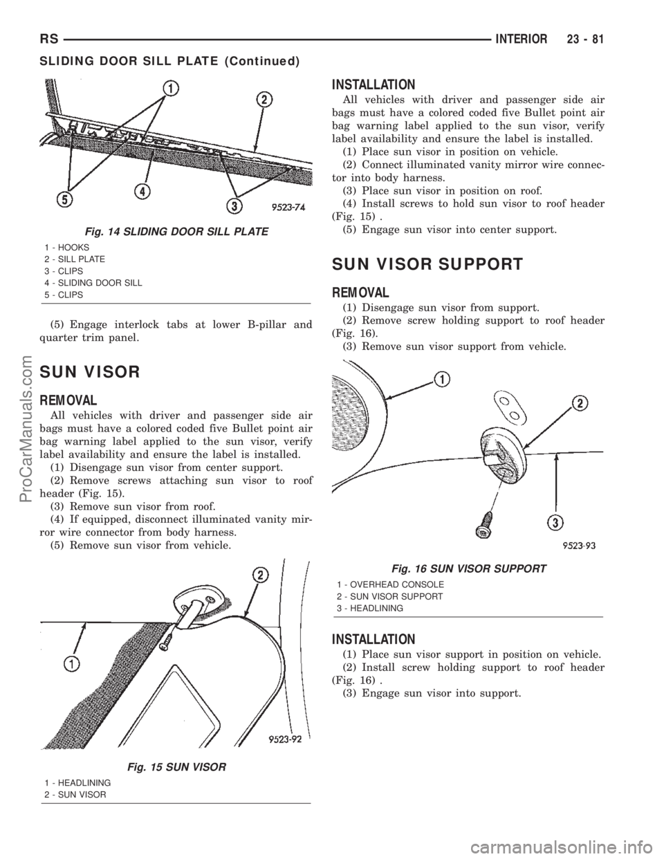
(2) Remove screws attaching sun visor to roof
header (Fig. 15).
(3) Remove sun visor from roof.
(4) If equipped, disconnect illuminated vanity mir-
ror wire connector from body harness.
(5) Remove sun visor from vehicle.
INSTALLATION
All vehicles with driver and passenger side air
bags must have a colored coded five Bullet point air
bag warning label applied to the sun visor, verify
label availability and ensure the label is installed.
(1) Place sun visor in position on vehicle.
(2) Connect illuminated vanity mirror wire connec-
tor into body harness.
(3) Place sun visor in position on roof.
(4) Install screws to hold sun visor to roof header
(Fig. 15) .
(5) Engage sun visor into center support.
SUN VISOR SUPPORT
REMOVAL
(1) Disengage sun visor from support.
(2) Remove screw holding support to roof header
(Fig. 16).
(3) Remove sun visor support from vehicle.
INSTALLATION
(1) Place sun visor support in position on vehicle.
(2) Install screw holding support to roof header
(Fig. 16) .
(3) Engage sun visor into support.
Fig. 14 SLIDING DOOR SILL PLATE
1 - HOOKS
2 - SILL PLATE
3 - CLIPS
4 - SLIDING DOOR SILL
5 - CLIPS
Fig. 15 SUN VISOR
1 - HEADLINING
2 - SUN VISOR
Fig. 16 SUN VISOR SUPPORT
1 - OVERHEAD CONSOLE
2 - SUN VISOR SUPPORT
3 - HEADLINING
RSINTERIOR23-81
SLIDING DOOR SILL PLATE (Continued)
ProCarManuals.com
Page 2079 of 2399
FRONT SEAT TRACK - REAR
COVER
REMOVAL
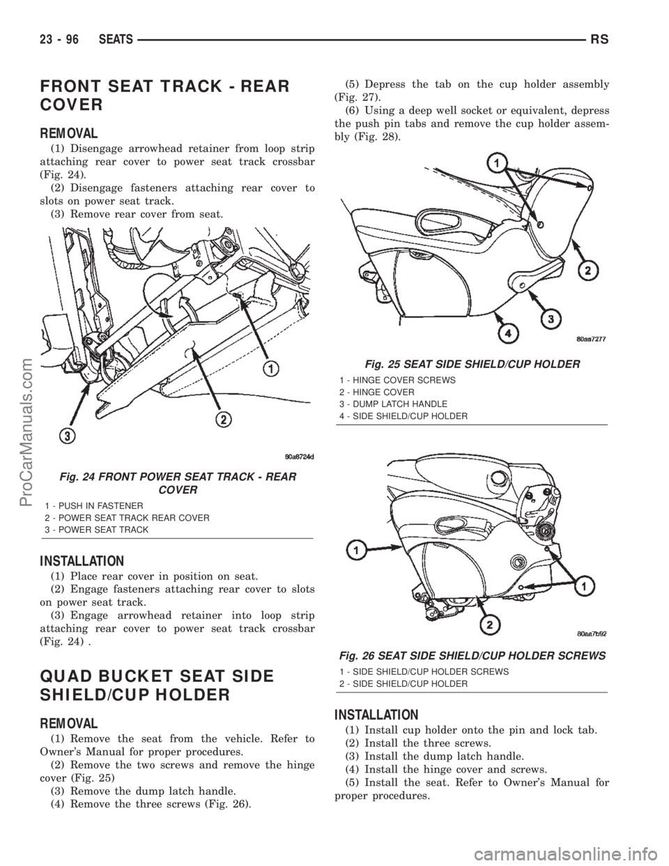
(1) Disengage arrowhead retainer from loop strip
attaching rear cover to power seat track crossbar
(Fig. 24).
(2) Disengage fasteners attaching rear cover to
slots on power seat track.
(3) Remove rear cover from seat.
INSTALLATION
(1) Place rear cover in position on seat.
(2) Engage fasteners attaching rear cover to slots
on power seat track.
(3) Engage arrowhead retainer into loop strip
attaching rear cover to power seat track crossbar
(Fig. 24) .
QUAD BUCKET SEAT SIDE
SHIELD/CUP HOLDER
REMOVAL
(1) Remove the seat from the vehicle. Refer to
Owner's Manual for proper procedures.
(2) Remove the two screws and remove the hinge
cover (Fig. 25)
(3) Remove the dump latch handle.
(4) Remove the three screws (Fig. 26).(5) Depress the tab on the cup holder assembly
(Fig. 27).
(6) Using a deep well socket or equivalent, depress
the push pin tabs and remove the cup holder assem-
bly (Fig. 28).
INSTALLATION
(1) Install cup holder onto the pin and lock tab.
(2) Install the three screws.
(3) Install the dump latch handle.
(4) Install the hinge cover and screws.
(5) Install the seat. Refer to Owner's Manual for
proper procedures.
Fig. 24 FRONT POWER SEAT TRACK - REAR
COVER
1 - PUSH IN FASTENER
2 - POWER SEAT TRACK REAR COVER
3 - POWER SEAT TRACK
Fig. 25 SEAT SIDE SHIELD/CUP HOLDER
1 - HINGE COVER SCREWS
2 - HINGE COVER
3 - DUMP LATCH HANDLE
4 - SIDE SHIELD/CUP HOLDER
Fig. 26 SEAT SIDE SHIELD/CUP HOLDER SCREWS
1 - SIDE SHIELD/CUP HOLDER SCREWS
2 - SIDE SHIELD/CUP HOLDER
23 - 96 SEATSRS
ProCarManuals.com
Page 2087 of 2399
INSTALLATION
(1) Place track in position on seat riser.
(2) Install nuts attaching track to seat riser. (Fig.
41). Tighten nuts to 48 N´m (35 ft. lbs.) torque.
(3) Engage seat track adjuster link wire onto track
being installed.
(4) Install second row seat into vehicle.
PLASTIC GROCERY BAG
RETAINER
REMOVAL
3-PASS BENCH SEAT
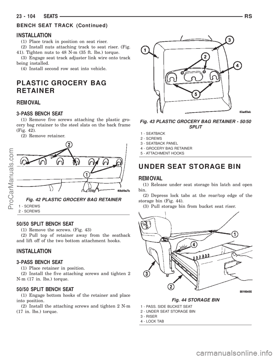
(1) Remove five screws attaching the plastic gro-
cery bag retainer to the steel slats on the back frame
(Fig. 42).
(2) Remove retainer.
50/50 SPLIT BENCH SEAT
(1) Remove the screws. (Fig. 43)
(2) Pull top of retainer away from the seatback
and lift off of the two bottom attachment hooks.
INSTALLATION
3-PASS BENCH SEAT
(1) Place retainer in position.
(2) Install the five attaching screws and tighten 2
N´m (17 in. lbs.) torque.
50/50 SPLIT BENCH SEAT
(1) Engage bottom hooks of the retainer and place
into position.
(2) Install the attaching screws and tighten 2 N´m
(17 in. lbs.) torque.
UNDER SEAT STORAGE BIN
REMOVAL
(1) Release under seat storage bin latch and open
bin.
(2) Depress lock tabs at the rear/top edge of the
storage bin (Fig. 44).
(3) Pull storage bin from bucket seat riser.
Fig. 42 PLASTIC GROCERY BAG RETAINER
1 - SCREWS
2 - SCREWS
Fig. 43 PLASTIC GROCERY BAG RETAINER - 50/50
SPLIT
1 - SEATBACK
2 - SCREWS
3 - SEATBACK PANEL
4 - GROCERY BAG RETAINER
5 - ATTACHMENT HOOKS
Fig. 44 STORAGE BIN
1 - PASS. SIDE BUCKET SEAT
2 - UNDER SEAT STORAGE BIN
3 - RISER
4 - LOCK TAB
23 - 104 SEATSRS
BENCH SEAT TRACK (Continued)
ProCarManuals.com
Page 2088 of 2399
INSTALLATION
(1) Engage storage bin tracks into guides on each
side of seat riser.
(2) Push storage bin inward until lock tabs snap
past retaining ridge on tracks
(3) Verify storage bin latch operation.
UNDER SEAT STORAGE BIN
GUIDE
REMOVAL
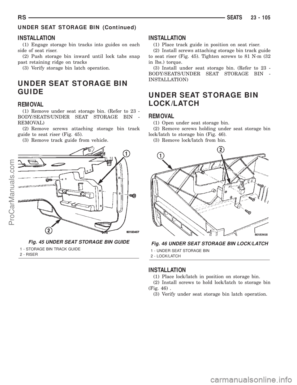
(1) Remove under seat storage bin. (Refer to 23 -
BODY/SEATS/UNDER SEAT STORAGE BIN -
REMOVAL)
(2) Remove screws attaching storage bin track
guide to seat riser (Fig. 45).
(3) Remove track guide from vehicle.
INSTALLATION
(1) Place track guide in position on seat riser.
(2) Install screws attaching storage bin track guide
to seat riser (Fig. 45). Tighten screws to 81 N´m (32
in lbs.) torque.
(3) Install under seat storage bin. (Refer to 23 -
BODY/SEATS/UNDER SEAT STORAGE BIN -
INSTALLATION)
UNDER SEAT STORAGE BIN
LOCK/LATCH
REMOVAL
(1) Open under seat storage bin.
(2) Remove screws holding under seat storage bin
lock/latch to storage bin (Fig. 46).
(3) Remove lock/latch from bin.
INSTALLATION
(1) Place lock/latch in position on storage bin.
(2) Install screws to hold lock/latch to storage bin
(Fig. 46) .
(3) Verify under seat storage bin latch operation.
Fig. 45 UNDER SEAT STORAGE BIN GUIDE
1 - STORAGE BIN TRACK GUIDE
2 - RISER
Fig. 46 UNDER SEAT STORAGE BIN LOCK/LATCH
1 - UNDER SEAT STORAGE BIN
2 - LOCK/LATCH
RSSEATS23 - 105
UNDER SEAT STORAGE BIN (Continued)
ProCarManuals.com
Page 2245 of 2399
FRONT CONTROL PANEL
The front control panel and integral computer is
mounted in the instrument panel.
The instrument panel mounted control and inte-
gral computer contains:
²a power button which allows the system to be
completely turned off.
²rear window defogger on/off switch.
²slide controls for completely independent side-to-
side temperature control of the discharge air. The full
range of temperature that the system can produce in
any mode is available on either side of the vehicle by
independently positioning the slide controls on the
instrument panel.
²air recirculation button. The Recirculate button
contains an LED that illuminates to show when the
function is in operation.
²an air conditioning button that allows the com-
pressor to be turned on/off. The Snowflake button
contains an LED that illuminates to shown when the
function is in operation.
²rotary knobs for front and rear fan speed selec-
tion.
²a rotary knob for mode control.
REAR CONTROL PANEL
A rear control panel centrally mounted on the
headliner has a rotary adjustment for temperature
and fan speed control of the rear unit by intermedi-
ate seat passengers when the front control rear knob
is set to the rear position.
DESCRIPTION - THREE ZONE AUTOMATIC
TEMPERATURE CONTROL
The Three-Zone Automatic Temperature Control
(ATC) allows occupants to select a comfort tempera-
ture, which is the perceived temperature level not
the actual passenger compartment air temperature.
The Three Zone Automatic Temperature Control
system includes a dust and odor air filter. The filter
element is the same size as the air conditioning evap-
orator to ensure ample capacity. A door at the base of
the heater and air conditioning housing below the
glove box provides easy access to the filter element.
The ATC computer utilizes integrated circuitry and
information carried on the Programmable Communi-
cations Interface (PCI) data bus network to monitor
many sensors and switch inputs throughout the vehi-
cle. In response to those inputs, the internal circuitry
and programming of the ATC computer allow it to
control electronic functions and features of the ATC
system. The inputs to the ATC computer are:
²Vehicle Speed/Engine RPM± The ATC com-
puter monitors engine RPM, vehicle speed and Man-
ifold Absolute Pressure information from the PCM.²Coolant Temperature± ATC computer moni-
tors Coolant temperature received from the PCM and
converts it to degrees Fahrenheit.
²Ambient Temperature± ATC computer moni-
tors Ambient temperature from the Compass Mini
Trip Computer (CMTC) and converts it to degrees
Fahrenheit.
²Engine Miscellaneous Sensor Status±ATC
computer monitors A/C disable information from the
PCM.
²Refrigerant Pressure± ATC computer moni-
tors Barometric Pressure, Intake Air Temperature,
High Side Pressure and Methanol Content as broad-
cast by the PCM.
²Door Ajar Status± The ATC computer moni-
tors Driver Front Door, Passenger Front Door, Left
Rear Door, Right Rear Door and Liftgate ajar infor-
mation, as identified by the Body Control Module
(BCM), to determine if all in-car temperatures should
be maintained.
²Dimming± The ATC computer monitors dim-
ming status from the BCM to determine the required
level of brightness and will dim accordingly.
²Vehicle Odometer± The ATC computer moni-
tors the vehicle odometer information from the BCM
to prevent flashing the VF tube icons if the manual
motor calibration or manual cool down tests have
failed. Flashing of the display icons will cease when
the vehicle odometer is greater than 3 miles.
²English Metric± The ATC computer monitors
the English/Metric information broadcast by the
CMTC. The set temp displays for both the front and
rear control heads will be set accordingly.
²Vehicle Identification Number± The ATC
computer monitors the last eight characters of the
VIN broadcast by the PCM and compares it to the
information stored in EEPROM. If it is different, the
new number will be stored over the old one and a
motor calibration shall be initiated.
²A/C System Information± The ATC computer
will send a message for Evaporator Temperature too
Low, Fan Blower Relay status, Evaporator Sensor
Failure, Rear Window Defogger Relay and A/C Select.
FRONT CONTROL PANEL
The front control panel and integral computer is
mounted in the instrument panel.
The instrument panel mounted control and inte-
gral computer contains:
²A power button which allows the system to be
completely turned off. The display is blank when the
system is off.
²Three rocker switches that select comfort tem-
peratures from 15É to 30É C (59É to 85É F), which are
shown in the vacuum-fluorescent digital control dis-
play. If the set temp is 59 and the down button is
24 - 2 HEATING & AIR CONDITIONINGRS
HEATING & AIR CONDITIONING (Continued)
ProCarManuals.com
Page 2254 of 2399
REMOVAL
(1) Disconnect and isolate the battery negative
cable.
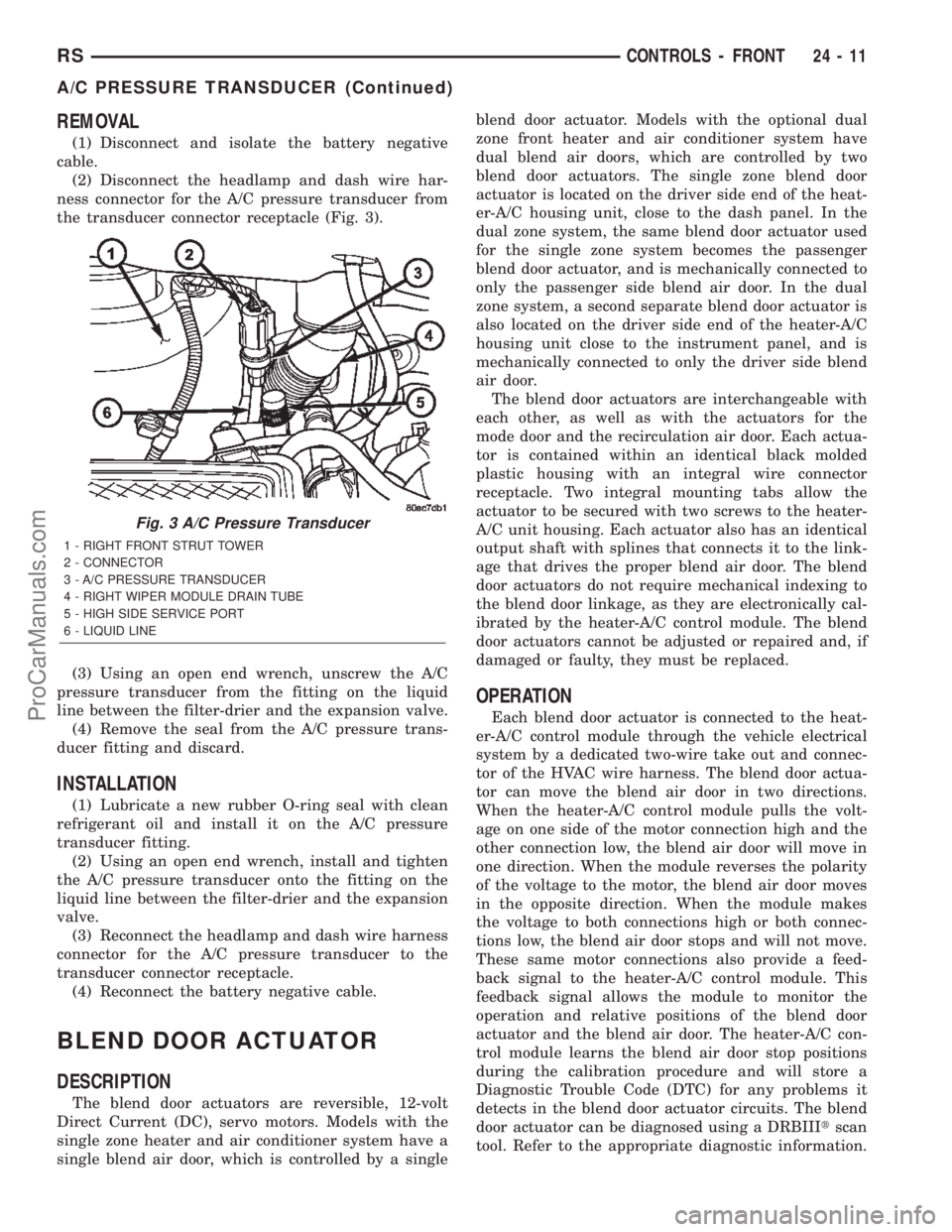
(2) Disconnect the headlamp and dash wire har-
ness connector for the A/C pressure transducer from
the transducer connector receptacle (Fig. 3).
(3) Using an open end wrench, unscrew the A/C
pressure transducer from the fitting on the liquid
line between the filter-drier and the expansion valve.
(4) Remove the seal from the A/C pressure trans-
ducer fitting and discard.
INSTALLATION
(1) Lubricate a new rubber O-ring seal with clean
refrigerant oil and install it on the A/C pressure
transducer fitting.
(2) Using an open end wrench, install and tighten
the A/C pressure transducer onto the fitting on the
liquid line between the filter-drier and the expansion
valve.
(3) Reconnect the headlamp and dash wire harness
connector for the A/C pressure transducer to the
transducer connector receptacle.
(4) Reconnect the battery negative cable.
BLEND DOOR ACTUATOR
DESCRIPTION
The blend door actuators are reversible, 12-volt
Direct Current (DC), servo motors. Models with the
single zone heater and air conditioner system have a
single blend air door, which is controlled by a singleblend door actuator. Models with the optional dual
zone front heater and air conditioner system have
dual blend air doors, which are controlled by two
blend door actuators. The single zone blend door
actuator is located on the driver side end of the heat-
er-A/C housing unit, close to the dash panel. In the
dual zone system, the same blend door actuator used
for the single zone system becomes the passenger
blend door actuator, and is mechanically connected to
only the passenger side blend air door. In the dual
zone system, a second separate blend door actuator is
also located on the driver side end of the heater-A/C
housing unit close to the instrument panel, and is
mechanically connected to only the driver side blend
air door.
The blend door actuators are interchangeable with
each other, as well as with the actuators for the
mode door and the recirculation air door. Each actua-
tor is contained within an identical black molded
plastic housing with an integral wire connector
receptacle. Two integral mounting tabs allow the
actuator to be secured with two screws to the heater-
A/C unit housing. Each actuator also has an identical
output shaft with splines that connects it to the link-
age that drives the proper blend air door. The blend
door actuators do not require mechanical indexing to
the blend door linkage, as they are electronically cal-
ibrated by the heater-A/C control module. The blend
door actuators cannot be adjusted or repaired and, if
damaged or faulty, they must be replaced.
OPERATION
Each blend door actuator is connected to the heat-
er-A/C control module through the vehicle electrical
system by a dedicated two-wire take out and connec-
tor of the HVAC wire harness. The blend door actua-
tor can move the blend air door in two directions.
When the heater-A/C control module pulls the volt-
age on one side of the motor connection high and the
other connection low, the blend air door will move in
one direction. When the module reverses the polarity
of the voltage to the motor, the blend air door moves
in the opposite direction. When the module makes
the voltage to both connections high or both connec-
tions low, the blend air door stops and will not move.
These same motor connections also provide a feed-
back signal to the heater-A/C control module. This
feedback signal allows the module to monitor the
operation and relative positions of the blend door
actuator and the blend air door. The heater-A/C con-
trol module learns the blend air door stop positions
during the calibration procedure and will store a
Diagnostic Trouble Code (DTC) for any problems it
detects in the blend door actuator circuits. The blend
door actuator can be diagnosed using a DRBIIItscan
tool. Refer to the appropriate diagnostic information.
Fig. 3 A/C Pressure Transducer
1 - RIGHT FRONT STRUT TOWER
2 - CONNECTOR
3 - A/C PRESSURE TRANSDUCER
4 - RIGHT WIPER MODULE DRAIN TUBE
5 - HIGH SIDE SERVICE PORT
6 - LIQUID LINE
RSCONTROLS - FRONT24-11
A/C PRESSURE TRANSDUCER (Continued)
ProCarManuals.com
Page 2255 of 2399
REMOVAL
The single zone heating and air conditioning sys-
tem is equipped with a single blend door actuator.
The dual zone system has two blend door actuators,
one for the driver side blend air door and one for the
passenger side blend air door. The same service pro-
cedures can be used for each of these actuators.
WARNING: ON VEHICLES EQUIPPED WITH AIR-
BAGS, DISABLE THE AIRBAG SYSTEM BEFORE
ATTEMPTING ANY STEERING WHEEL, STEERING
COLUMN, OR INSTRUMENT PANEL COMPONENT
DIAGNOSIS OR SERVICE. DISCONNECT AND ISO-
LATE THE BATTERY NEGATIVE (GROUND) CABLE,
THEN WAIT TWO MINUTES FOR THE AIRBAG SYS-
TEM CAPACITOR TO DISCHARGE BEFORE PER-
FORMING FURTHER DIAGNOSIS OR SERVICE. THIS
IS THE ONLY SURE WAY TO DISABLE THE AIRBAG
SYSTEM. FAILURE TO TAKE THE PROPER PRE-
CAUTIONS COULD RESULT IN ACCIDENTAL AIR-
BAG DEPLOYMENT AND POSSIBLE PERSONAL
INJURY.
(1) Disconnect and isolate the battery negative
cable.
(2) Remove the silencer from beneath the driver
side end of the instrument panel. (Refer to 23 -
BODY/INSTRUMENT PANEL/INSTRUMENT
PANEL SILENCER - REMOVAL).
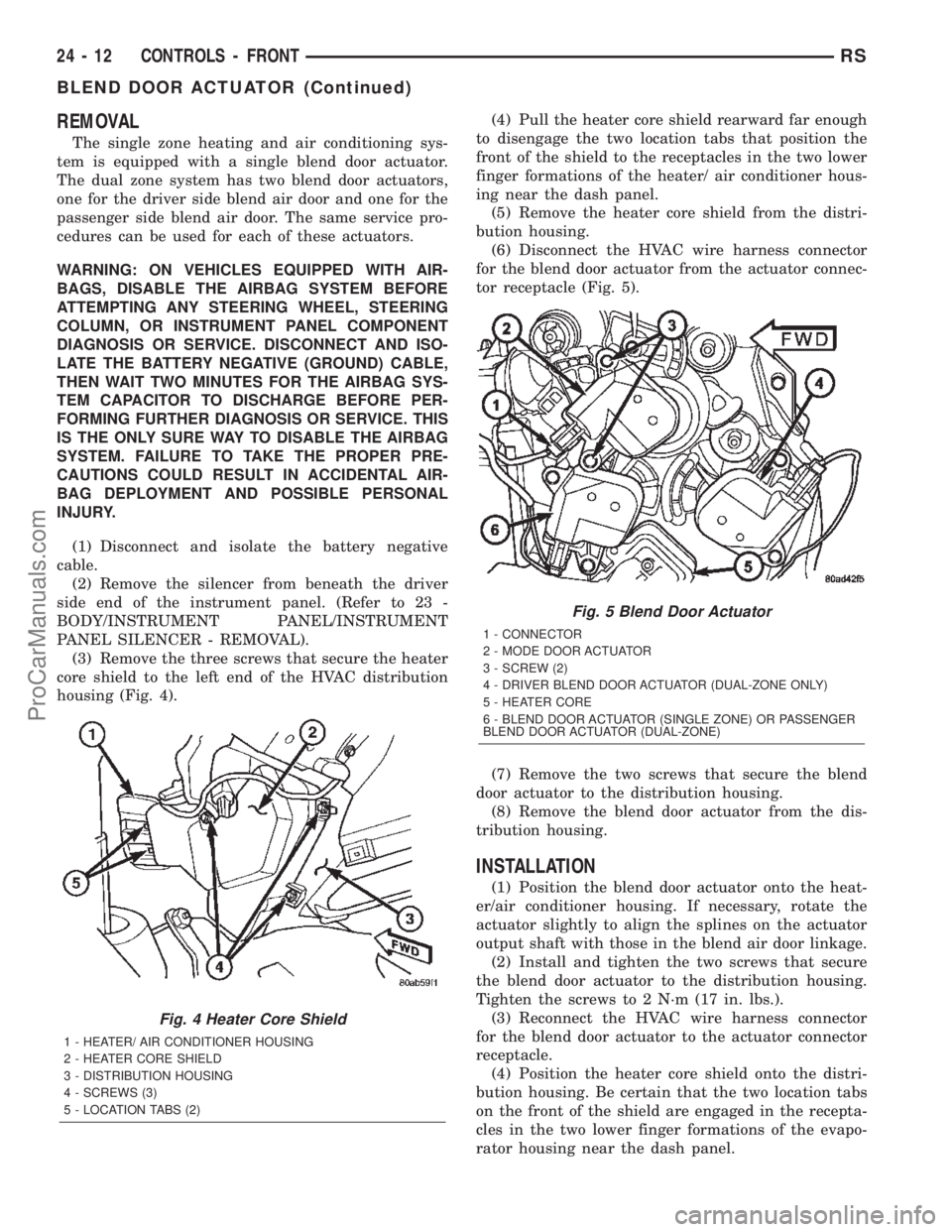
(3) Remove the three screws that secure the heater
core shield to the left end of the HVAC distribution
housing (Fig. 4).(4) Pull the heater core shield rearward far enough
to disengage the two location tabs that position the
front of the shield to the receptacles in the two lower
finger formations of the heater/ air conditioner hous-
ing near the dash panel.
(5) Remove the heater core shield from the distri-
bution housing.
(6) Disconnect the HVAC wire harness connector
for the blend door actuator from the actuator connec-
tor receptacle (Fig. 5).
(7) Remove the two screws that secure the blend
door actuator to the distribution housing.
(8) Remove the blend door actuator from the dis-
tribution housing.
INSTALLATION
(1) Position the blend door actuator onto the heat-
er/air conditioner housing. If necessary, rotate the
actuator slightly to align the splines on the actuator
output shaft with those in the blend air door linkage.
(2) Install and tighten the two screws that secure
the blend door actuator to the distribution housing.
Tighten the screws to 2 N´m (17 in. lbs.).
(3) Reconnect the HVAC wire harness connector
for the blend door actuator to the actuator connector
receptacle.
(4) Position the heater core shield onto the distri-
bution housing. Be certain that the two location tabs
on the front of the shield are engaged in the recepta-
cles in the two lower finger formations of the evapo-
rator housing near the dash panel.
Fig. 4 Heater Core Shield
1 - HEATER/ AIR CONDITIONER HOUSING
2 - HEATER CORE SHIELD
3 - DISTRIBUTION HOUSING
4 - SCREWS (3)
5 - LOCATION TABS (2)
Fig. 5 Blend Door Actuator
1 - CONNECTOR
2 - MODE DOOR ACTUATOR
3 - SCREW (2)
4 - DRIVER BLEND DOOR ACTUATOR (DUAL-ZONE ONLY)
5 - HEATER CORE
6 - BLEND DOOR ACTUATOR (SINGLE ZONE) OR PASSENGER
BLEND DOOR ACTUATOR (DUAL-ZONE)
24 - 12 CONTROLS - FRONTRS
BLEND DOOR ACTUATOR (Continued)
ProCarManuals.com