Page 1694 of 2399
TRANSFER SYSTEM -
TRANSFER SHAFT/GEAR/
BEARING
REMOVAL
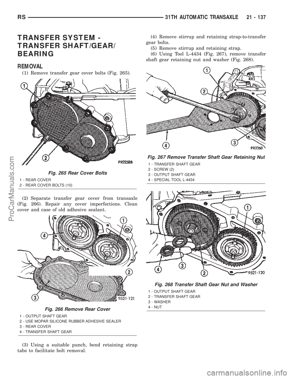
(1) Remove transfer gear cover bolts (Fig. 265).
(2) Separate transfer gear cover from transaxle
(Fig. 266). Repair any cover imperfections. Clean
cover and case of old adhesive sealant.
(3) Using a suitable punch, bend retaining strap
tabs to facilitate bolt removal.(4) Remove stirrup and retaining strap-to-transfer
gear bolts.
(5) Remove stirrup and retaining strap.
(6) Using Tool L-4434 (Fig. 267), remove transfer
shaft gear retaining nut and washer (Fig. 268).
Fig. 265 Rear Cover Bolts
1 - REAR COVER
2 - REAR COVER BOLTS (10)
Fig. 266 Remove Rear Cover
1 - OUTPUT SHAFT GEAR
2 - USE MOPAR SILICONE RUBBER ADHESIVE SEALER
3 - REAR COVER
4 - TRANSFER SHAFT GEAR
Fig. 267 Remove Transfer Shaft Gear Retaining Nut
1 - TRANSFER SHAFT GEAR
2 - SCREW (2)
3 - OUTPUT SHAFT GEAR
4 - SPECIAL TOOL L-4434
Fig. 268 Transfer Shaft Gear Nut and Washer
1 - OUTPUT SHAFT GEAR
2 - TRANSFER SHAFT GEAR
3 - WASHER
4 - NUT
RS31TH AUTOMATIC TRANSAXLE21 - 137
ProCarManuals.com
Page 1701 of 2399
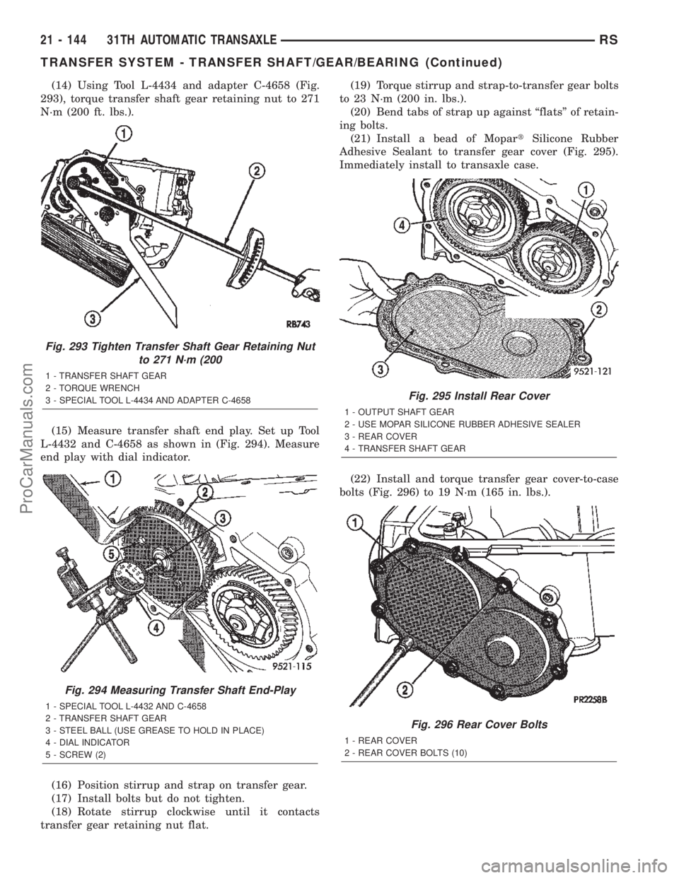
(14) Using Tool L-4434 and adapter C-4658 (Fig.
293), torque transfer shaft gear retaining nut to 271
N´m (200 ft. lbs.).
(15) Measure transfer shaft end play. Set up Tool
L-4432 and C-4658 as shown in (Fig. 294). Measure
end play with dial indicator.
(16) Position stirrup and strap on transfer gear.
(17) Install bolts but do not tighten.
(18) Rotate stirrup clockwise until it contacts
transfer gear retaining nut flat.(19) Torque stirrup and strap-to-transfer gear bolts
to 23 N´m (200 in. lbs.).
(20) Bend tabs of strap up against ªflatsº of retain-
ing bolts.
(21) Install a bead of MopartSilicone Rubber
Adhesive Sealant to transfer gear cover (Fig. 295).
Immediately install to transaxle case.
(22) Install and torque transfer gear cover-to-case
bolts (Fig. 296) to 19 N´m (165 in. lbs.).
Fig. 293 Tighten Transfer Shaft Gear Retaining Nut
to 271 N´m (200
1 - TRANSFER SHAFT GEAR
2 - TORQUE WRENCH
3 - SPECIAL TOOL L-4434 AND ADAPTER C-4658
Fig. 294 Measuring Transfer Shaft End-Play
1 - SPECIAL TOOL L-4432 AND C-4658
2 - TRANSFER SHAFT GEAR
3 - STEEL BALL (USE GREASE TO HOLD IN PLACE)
4 - DIAL INDICATOR
5 - SCREW (2)
Fig. 295 Install Rear Cover
1 - OUTPUT SHAFT GEAR
2 - USE MOPAR SILICONE RUBBER ADHESIVE SEALER
3 - REAR COVER
4 - TRANSFER SHAFT GEAR
Fig. 296 Rear Cover Bolts
1 - REAR COVER
2 - REAR COVER BOLTS (10)
21 - 144 31TH AUTOMATIC TRANSAXLERS
TRANSFER SYSTEM - TRANSFER SHAFT/GEAR/BEARING (Continued)
ProCarManuals.com
Page 1735 of 2399
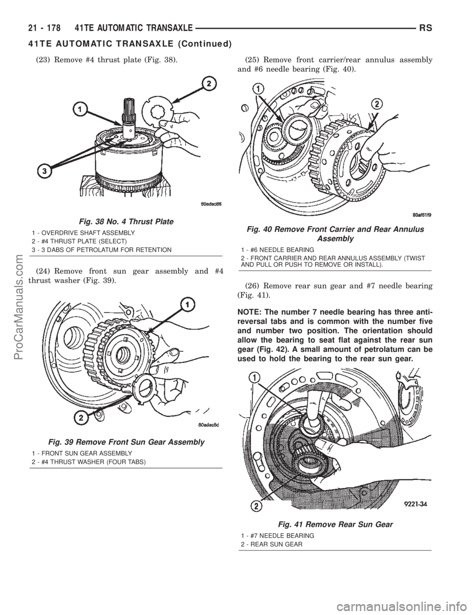
(23) Remove #4 thrust plate (Fig. 38).
(24) Remove front sun gear assembly and #4
thrust washer (Fig. 39).(25) Remove front carrier/rear annulus assembly
and #6 needle bearing (Fig. 40).
(26) Remove rear sun gear and #7 needle bearing
(Fig. 41).
NOTE: The number 7 needle bearing has three anti-
reversal tabs and is common with the number five
and number two position. The orientation should
allow the bearing to seat flat against the rear sun
gear (Fig. 42). A small amount of petrolatum can be
used to hold the bearing to the rear sun gear.
Fig. 38 No. 4 Thrust Plate
1 - OVERDRIVE SHAFT ASSEMBLY
2 - #4 THRUST PLATE (SELECT)
3 - 3 DABS OF PETROLATUM FOR RETENTION
Fig. 39 Remove Front Sun Gear Assembly
1 - FRONT SUN GEAR ASSEMBLY
2 - #4 THRUST WASHER (FOUR TABS)
Fig. 40 Remove Front Carrier and Rear Annulus
Assembly
1 - #6 NEEDLE BEARING
2 - FRONT CARRIER AND REAR ANNULUS ASSEMBLY (TWIST
AND PULL OR PUSH TO REMOVE OR INSTALL).
Fig. 41 Remove Rear Sun Gear
1 - #7 NEEDLE BEARING
2 - REAR SUN GEAR
21 - 178 41TE AUTOMATIC TRANSAXLERS
41TE AUTOMATIC TRANSAXLE (Continued)
ProCarManuals.com
Page 1755 of 2399
(23) Bend tabs on strap up against flats of bolts
(Fig. 112).
(24) Install transfer shaft bearing cone using Tool
6052 (Fig. 113).(25) Install bearing cup and oil baffle to transfer
shaft (Fig. 114).
(26) Using Tool 5049A, install transfer shaft (Fig.
115).
Fig. 112 Bend Tabs On Strap Up Against Flats Of
Bolts
1 - RETAINING STRAP TABS
2 - RETAINING STRAP
3 - STIRRUP
Fig. 113 Install Transfer Shaft Bearing Cone
1 - TOOL 6052
2 - NEW BEARING CONE
3 - TRANSFER SHAFT
4 - ARBOR PRESS RAM
Fig. 114 Install Bearing Cup to Shaft
1 - BEARING CUP
2 - BEARING CONE
3 - TRANSFER SHAFT
4 - OIL BAFFLE
5 - O-RING
Fig. 115 Install Transfer Shaft
1 - SPECIAL TOOL 5049±A
2 - TRANSFER SHAFT
3 - OUTPUT GEAR
21 - 198 41TE AUTOMATIC TRANSAXLERS
41TE AUTOMATIC TRANSAXLE (Continued)
ProCarManuals.com
Page 1763 of 2399
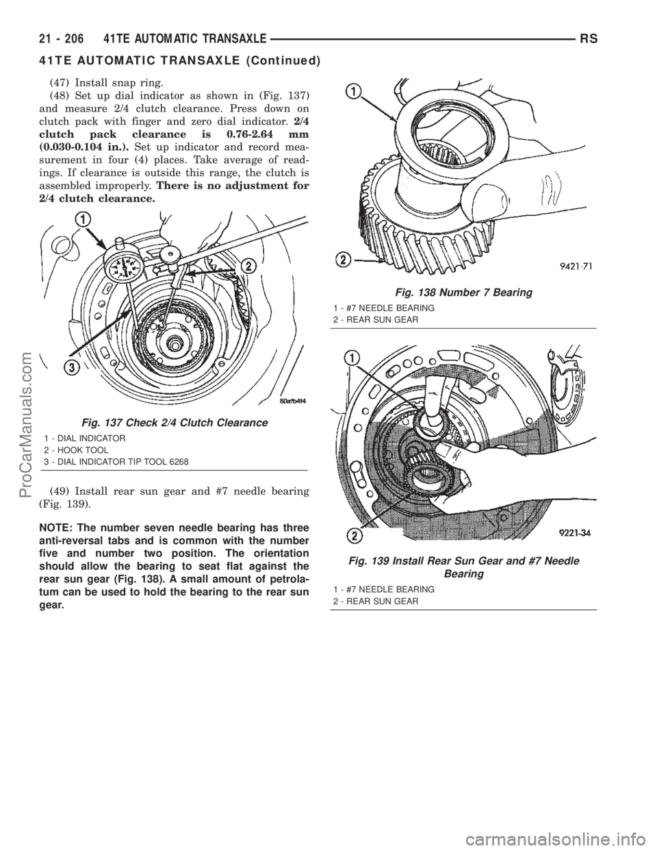
(47) Install snap ring.
(48) Set up dial indicator as shown in (Fig. 137)
and measure 2/4 clutch clearance. Press down on
clutch pack with finger and zero dial indicator.2/4
clutch pack clearance is 0.76-2.64 mm
(0.030-0.104 in.).Set up indicator and record mea-
surement in four (4) places. Take average of read-
ings. If clearance is outside this range, the clutch is
assembled improperly.There is no adjustment for
2/4 clutch clearance.
(49) Install rear sun gear and #7 needle bearing
(Fig. 139).
NOTE: The number seven needle bearing has three
anti-reversal tabs and is common with the number
five and number two position. The orientation
should allow the bearing to seat flat against the
rear sun gear (Fig. 138). A small amount of petrola-
tum can be used to hold the bearing to the rear sun
gear.
Fig. 137 Check 2/4 Clutch Clearance
1 - DIAL INDICATOR
2 - HOOK TOOL
3 - DIAL INDICATOR TIP TOOL 6268
Fig. 138 Number 7 Bearing
1 - #7 NEEDLE BEARING
2 - REAR SUN GEAR
Fig. 139 Install Rear Sun Gear and #7 Needle
Bearing
1 - #7 NEEDLE BEARING
2 - REAR SUN GEAR
21 - 206 41TE AUTOMATIC TRANSAXLERS
41TE AUTOMATIC TRANSAXLE (Continued)
ProCarManuals.com
Page 1764 of 2399
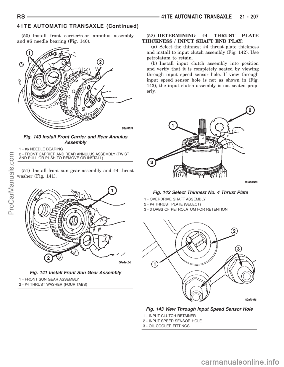
(50) Install front carrier/rear annulus assembly
and #6 needle bearing (Fig. 140).
(51) Install front sun gear assembly and #4 thrust
washer (Fig. 141).(52)DETERMINING #4 THRUST PLATE
THICKNESS / INPUT SHAFT END PLAY:
(a) Select the thinnest #4 thrust plate thickness
and install to input clutch assembly (Fig. 142). Use
petrolatum to retain.
(b) Install input clutch assembly into position
and verify that it is completely seated by viewing
through input speed sensor hole. If view through
input speed sensor hole is not as shown in (Fig.
143), the input clutch assembly is not seated prop-
erly.
Fig. 142 Select Thinnest No. 4 Thrust Plate
1 - OVERDRIVE SHAFT ASSEMBLY
2 - #4 THRUST PLATE (SELECT)
3 - 3 DABS OF PETROLATUM FOR RETENTION
Fig. 143 View Through Input Speed Sensor Hole
1 - INPUT CLUTCH RETAINER
2 - INPUT SPEED SENSOR HOLE
3 - OIL COOLER FITTINGS
Fig. 140 Install Front Carrier and Rear Annulus
Assembly
1 - #6 NEEDLE BEARING
2 - FRONT CARRIER AND REAR ANNULUS ASSEMBLY (TWIST
AND PULL OR PUSH TO REMOVE OR INSTALL).
Fig. 141 Install Front Sun Gear Assembly
1 - FRONT SUN GEAR ASSEMBLY
2 - #4 THRUST WASHER (FOUR TABS)
RS41TE AUTOMATIC TRANSAXLE21 - 207
41TE AUTOMATIC TRANSAXLE (Continued)
ProCarManuals.com
Page 1800 of 2399
ASSEMBLY
NOTE: The differential is serviced as an assembly.
Differential service is limited to bearing cups and
cones. Any other differential component failure
must be remedied by differential assembly and
transfer shaft replacement.
(1) Install side gear thrust washer to differential
case (Fig. 193).
(2) Install side gear to differential case (Fig. 194).(3) Install both pinion gears and washers to case,
while orientating washer tabs to notch in case (Fig.
195).
(4) Install pinion shaft (Fig. 196).
Fig. 193 Thrust Washer Installation
1 - THRUST WASHER
Fig. 194 Side Gear Installation
1 - DIFFERENTIAL SIDE GEAR
Fig. 195 Pinion Gear and Washer Installation
1 - PINION GEAR
2 - TABBED WASHER
3 - LOCATING TAB
4 - NOTCH
Fig. 196 Pinion Shaft Installation
1 - PINION SHAFT
RS41TE AUTOMATIC TRANSAXLE21 - 243
FINAL DRIVE (Continued)
ProCarManuals.com
Page 1815 of 2399
(10) Remove and inspect #3 & #4 thrust washers
(Fig. 236).(11) Remove the underdrive shaft assembly (Fig.
237).
(12) Remove the #2 needle bearing (Fig. 238).
Fig. 235 Overdrive Clutch Pack
1 - OVERDRIVE CLUTCH PLATE
2 - OVERDRIVE SHAFT ASSEMBLY
3 - OVERDRIVE CLUTCH DISC
Fig. 236 #3&4 Thrust Washers
1 - #3 THRUST PLATE (3 TABS)
2 - OD SHAFT ASSEMBLY
3 - #4 THRUST PLATE (3 SLOTS)
Fig. 237 Underdrive Shaft Assembly
1 - #3 THRUST WASHER (5 TABS)
2 - UNDERDRIVE SHAFT ASSEMBLY
Fig. 238 No. 2 Needle Bearing
1 - #2 NEEDLE BEARING (NOTE 3 TABS)
21 - 258 41TE AUTOMATIC TRANSAXLERS
INPUT CLUTCH ASSEMBLY (Continued)
ProCarManuals.com