2002 CHRYSLER CARAVAN check oil
[x] Cancel search: check oilPage 1856 of 2399
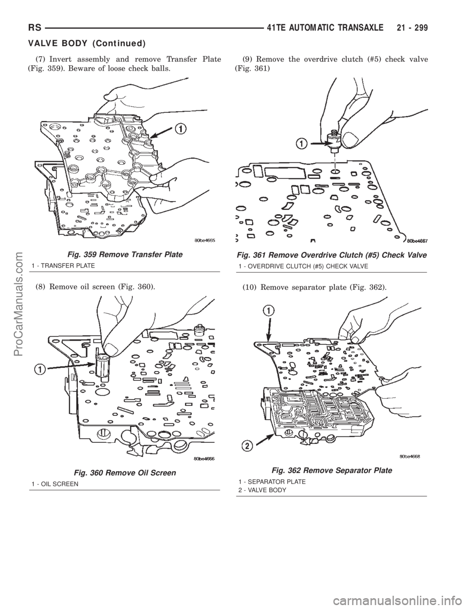
(7) Invert assembly and remove Transfer Plate
(Fig. 359). Beware of loose check balls.
(8) Remove oil screen (Fig. 360).(9) Remove the overdrive clutch (#5) check valve
(Fig. 361)
(10) Remove separator plate (Fig. 362).
Fig. 359 Remove Transfer Plate
1 - TRANSFER PLATE
Fig. 360 Remove Oil Screen
1 - OIL SCREEN
Fig. 361 Remove Overdrive Clutch (#5) Check Valve
1 - OVERDRIVE CLUTCH (#5) CHECK VALVE
Fig. 362 Remove Separator Plate
1 - SEPARATOR PLATE
2 - VALVE BODY
RS41TE AUTOMATIC TRANSAXLE21 - 299
VALVE BODY (Continued)
ProCarManuals.com
Page 1861 of 2399
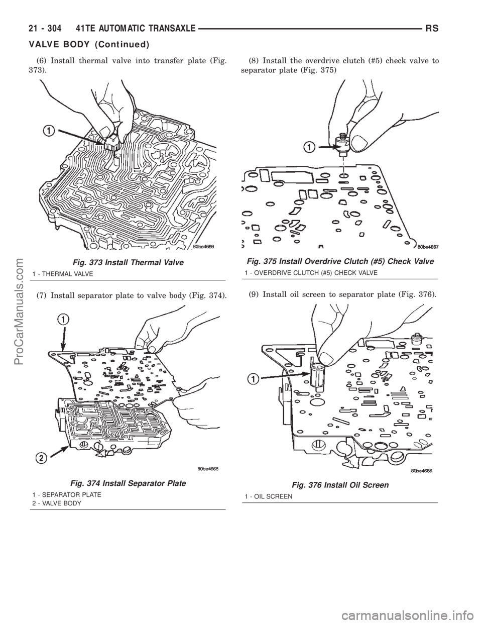
(6) Install thermal valve into transfer plate (Fig.
373).
(7) Install separator plate to valve body (Fig. 374).(8) Install the overdrive clutch (#5) check valve to
separator plate (Fig. 375)
(9) Install oil screen to separator plate (Fig. 376).
Fig. 373 Install Thermal Valve
1 - THERMAL VALVE
Fig. 374 Install Separator Plate
1 - SEPARATOR PLATE
2 - VALVE BODY
Fig. 375 Install Overdrive Clutch (#5) Check Valve
1 - OVERDRIVE CLUTCH (#5) CHECK VALVE
Fig. 376 Install Oil Screen
1 - OIL SCREEN
21 - 304 41TE AUTOMATIC TRANSAXLERS
VALVE BODY (Continued)
ProCarManuals.com
Page 1862 of 2399
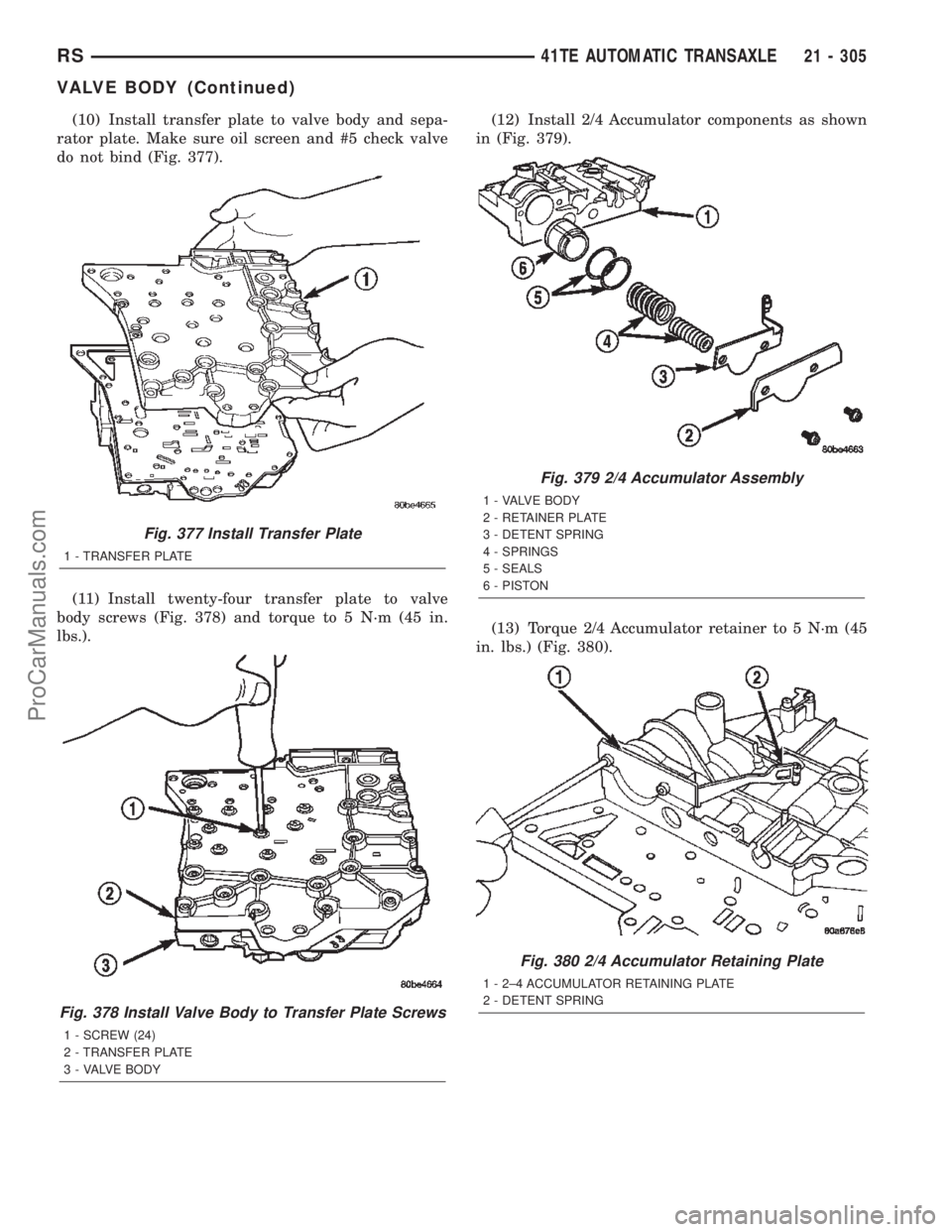
(10) Install transfer plate to valve body and sepa-
rator plate. Make sure oil screen and #5 check valve
do not bind (Fig. 377).
(11) Install twenty-four transfer plate to valve
body screws (Fig. 378) and torque to 5 N´m (45 in.
lbs.).(12) Install 2/4 Accumulator components as shown
in (Fig. 379).
(13) Torque 2/4 Accumulator retainer to 5 N´m (45
in. lbs.) (Fig. 380).
Fig. 377 Install Transfer Plate
1 - TRANSFER PLATE
Fig. 378 Install Valve Body to Transfer Plate Screws
1 - SCREW (24)
2 - TRANSFER PLATE
3 - VALVE BODY
Fig. 379 2/4 Accumulator Assembly
1 - VALVE BODY
2 - RETAINER PLATE
3 - DETENT SPRING
4 - SPRINGS
5 - SEALS
6 - PISTON
Fig. 380 2/4 Accumulator Retaining Plate
1 - 2±4 ACCUMULATOR RETAINING PLATE
2 - DETENT SPRING
RS41TE AUTOMATIC TRANSAXLE21 - 305
VALVE BODY (Continued)
ProCarManuals.com
Page 1875 of 2399
DIAGNOSIS AND TESTING - COMMON
PROBLEM CAUSES
The majority of transaxle malfunctions are a result
of:
²Insufficient lubrication
²Incorrect lubricant
²Misassembled or damaged internal components
²Improper operation
HARD SHIFTING
Hard shifting may be caused by a misadjusted
crossover cable. If hard shifting is accompanied by
gear clash, synchronizer clutch and stop rings or gear
teeth may be worn or damaged.
Hard shifting may also be caused by a binding or
broken shift cover mechanism. Remove shift cover
and verify smooth operation. Replace as necessary.
Misassembled synchronizer components also cause
shifting problems. Incorrectly installed synchronizer
sleeves, keys, balls, or springs can cause shift prob-
lems.
NOISY OPERATION
Transaxle noise is most often a result of worn or
damaged components. Chipped, broken gear or syn-
chronizer teeth, and brinnelled, spalled bearings all
cause noise.
Abnormal wear and damage to the internal compo-
nents is frequently the end result of insufficient
lubricant.
SLIPS OUT OF GEAR
Transaxle disengagement may be caused by mis-
aligned or damaged shift components, or worn teeth
on the drive gears or synchronizer components. Incor-
rect assembly also causes gear disengagement. Check
for missing snap rings.
LOW LUBRICANT LEVEL
Insufficient transaxle lubricant is usually the
result of leaks, or inaccurate fluid level check or refill
method. Leakage is evident by the presence of oil
around the leak point. If leakage is not evident, the
condition is probably the result of an underfill.
If air±powered lubrication equipment is used to fill
a transaxle, be sure the equipment is properly cali-
brated. Equipment out of calibration can lead to an
underfill condition.
CLUTCH PROBLEMS
Worn, damaged, or misaligned clutch components
can cause difficult shifting, gear clash, and noise.
A worn or damaged clutch disc, pressure plate, or
release bearing can cause hard shifting and gear
clash.
REMOVAL
REMOVAL - 2.4L GAS
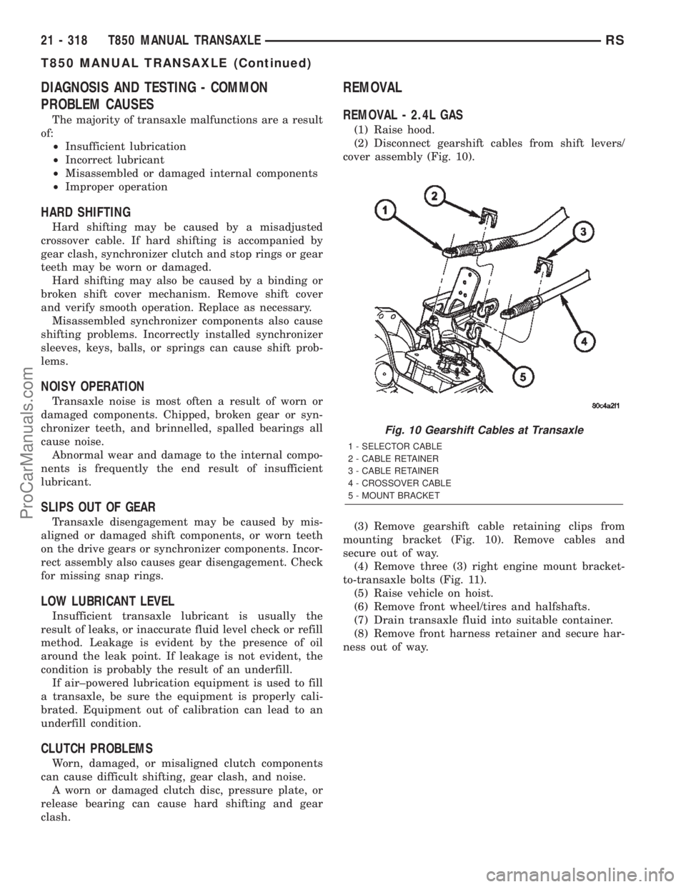
(1) Raise hood.
(2) Disconnect gearshift cables from shift levers/
cover assembly (Fig. 10).
(3) Remove gearshift cable retaining clips from
mounting bracket (Fig. 10). Remove cables and
secure out of way.
(4) Remove three (3) right engine mount bracket-
to-transaxle bolts (Fig. 11).
(5) Raise vehicle on hoist.
(6) Remove front wheel/tires and halfshafts.
(7) Drain transaxle fluid into suitable container.
(8) Remove front harness retainer and secure har-
ness out of way.
Fig. 10 Gearshift Cables at Transaxle
1 - SELECTOR CABLE
2 - CABLE RETAINER
3 - CABLE RETAINER
4 - CROSSOVER CABLE
5 - MOUNT BRACKET
21 - 318 T850 MANUAL TRANSAXLERS
T850 MANUAL TRANSAXLE (Continued)
ProCarManuals.com
Page 1900 of 2399
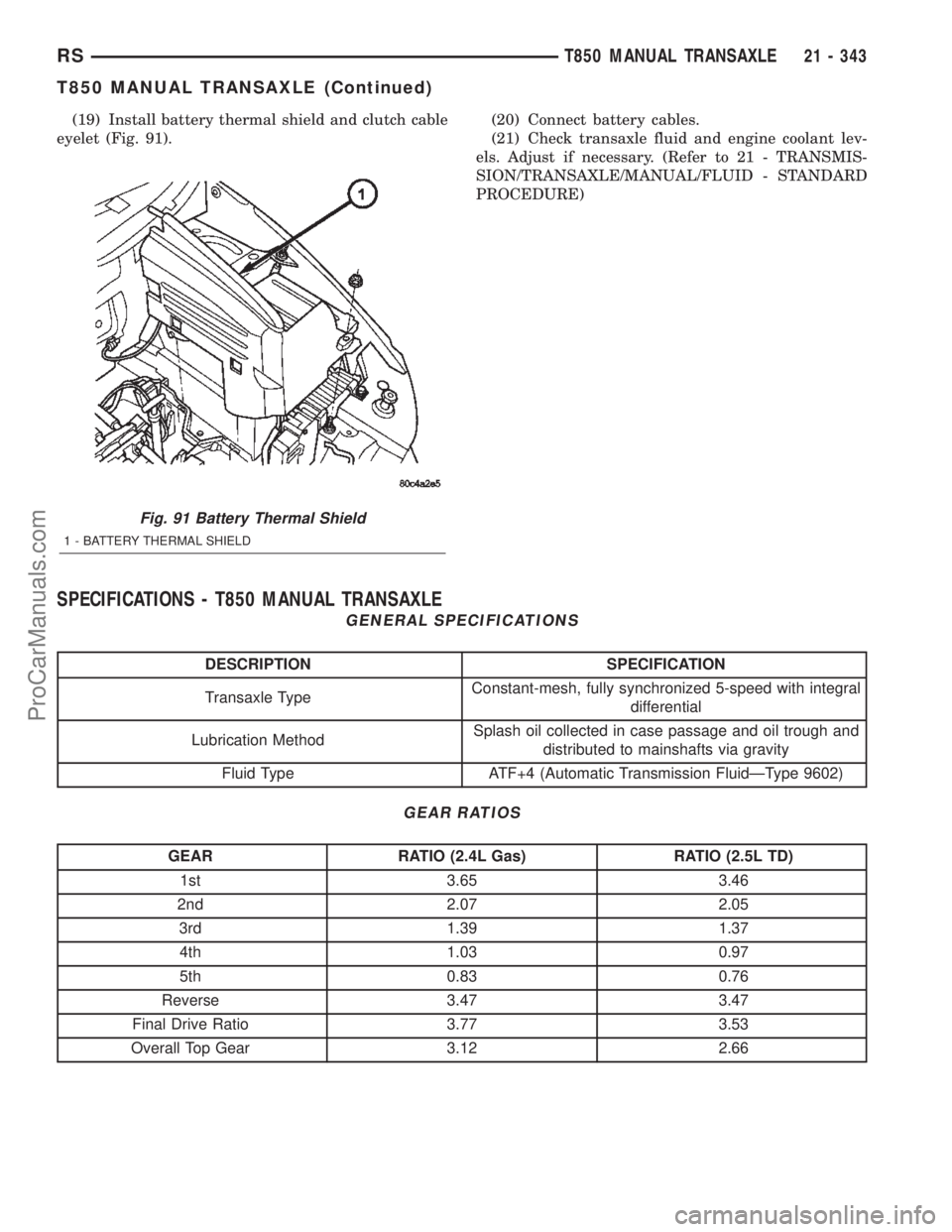
(19) Install battery thermal shield and clutch cable
eyelet (Fig. 91).(20) Connect battery cables.
(21) Check transaxle fluid and engine coolant lev-
els. Adjust if necessary. (Refer to 21 - TRANSMIS-
SION/TRANSAXLE/MANUAL/FLUID - STANDARD
PROCEDURE)
SPECIFICATIONS - T850 MANUAL TRANSAXLE
GENERAL SPECIFICATIONS
DESCRIPTION SPECIFICATION
Transaxle TypeConstant-mesh, fully synchronized 5-speed with integral
differential
Lubrication MethodSplash oil collected in case passage and oil trough and
distributed to mainshafts via gravity
Fluid Type ATF+4 (Automatic Transmission FluidÐType 9602)
GEAR RATIOS
GEAR RATIO (2.4L Gas) RATIO (2.5L TD)
1st 3.65 3.46
2nd 2.07 2.05
3rd 1.39 1.37
4th 1.03 0.97
5th 0.83 0.76
Reverse 3.47 3.47
Final Drive Ratio 3.77 3.53
Overall Top Gear 3.12 2.66
Fig. 91 Battery Thermal Shield
1 - BATTERY THERMAL SHIELD
RST850 MANUAL TRANSAXLE21 - 343
T850 MANUAL TRANSAXLE (Continued)
ProCarManuals.com
Page 1994 of 2399
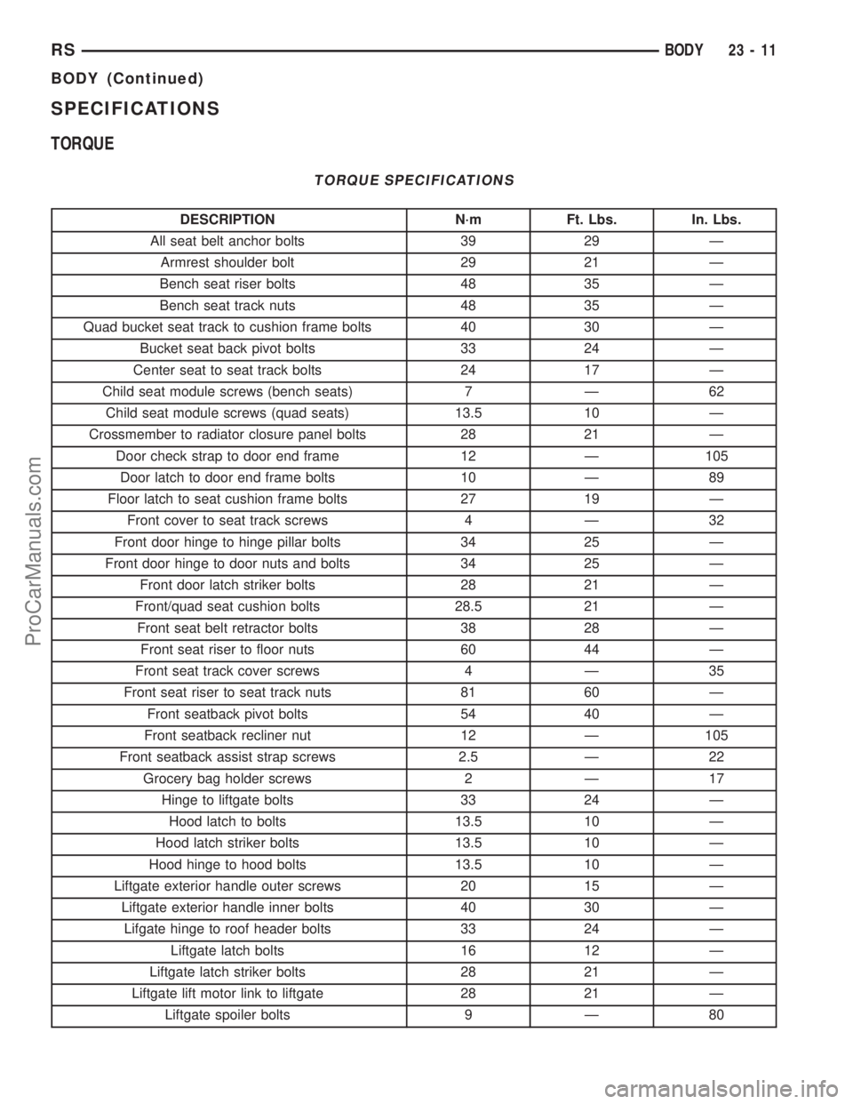
SPECIFICATIONS
TORQUE
TORQUE SPECIFICATIONS
DESCRIPTION N´m Ft. Lbs. In. Lbs.
All seat belt anchor bolts 39 29 Ð
Armrest shoulder bolt 29 21 Ð
Bench seat riser bolts 48 35 Ð
Bench seat track nuts 48 35 Ð
Quad bucket seat track to cushion frame bolts 40 30 Ð
Bucket seat back pivot bolts 33 24 Ð
Center seat to seat track bolts 24 17 Ð
Child seat module screws (bench seats) 7 Ð 62
Child seat module screws (quad seats) 13.5 10 Ð
Crossmember to radiator closure panel bolts 28 21 Ð
Door check strap to door end frame 12 Ð 105
Door latch to door end frame bolts 10 Ð 89
Floor latch to seat cushion frame bolts 27 19 Ð
Front cover to seat track screws 4 Ð 32
Front door hinge to hinge pillar bolts 34 25 Ð
Front door hinge to door nuts and bolts 34 25 Ð
Front door latch striker bolts 28 21 Ð
Front/quad seat cushion bolts 28.5 21 Ð
Front seat belt retractor bolts 38 28 Ð
Front seat riser to floor nuts 60 44 Ð
Front seat track cover screws 4 Ð 35
Front seat riser to seat track nuts 81 60 Ð
Front seatback pivot bolts 54 40 Ð
Front seatback recliner nut 12 Ð 105
Front seatback assist strap screws 2.5 Ð 22
Grocery bag holder screws 2 Ð 17
Hinge to liftgate bolts 33 24 Ð
Hood latch to bolts 13.5 10 Ð
Hood latch striker bolts 13.5 10 Ð
Hood hinge to hood bolts 13.5 10 Ð
Liftgate exterior handle outer screws 20 15 Ð
Liftgate exterior handle inner bolts 40 30 Ð
Lifgate hinge to roof header bolts 33 24 Ð
Liftgate latch bolts 16 12 Ð
Liftgate latch striker bolts 28 21 Ð
Liftgate lift motor link to liftgate 28 21 Ð
Liftgate spoiler bolts 9 Ð 80
RSBODY23-11
BODY (Continued)
ProCarManuals.com
Page 2258 of 2399
BLOWER MOTOR RESISTOR
DESCRIPTION
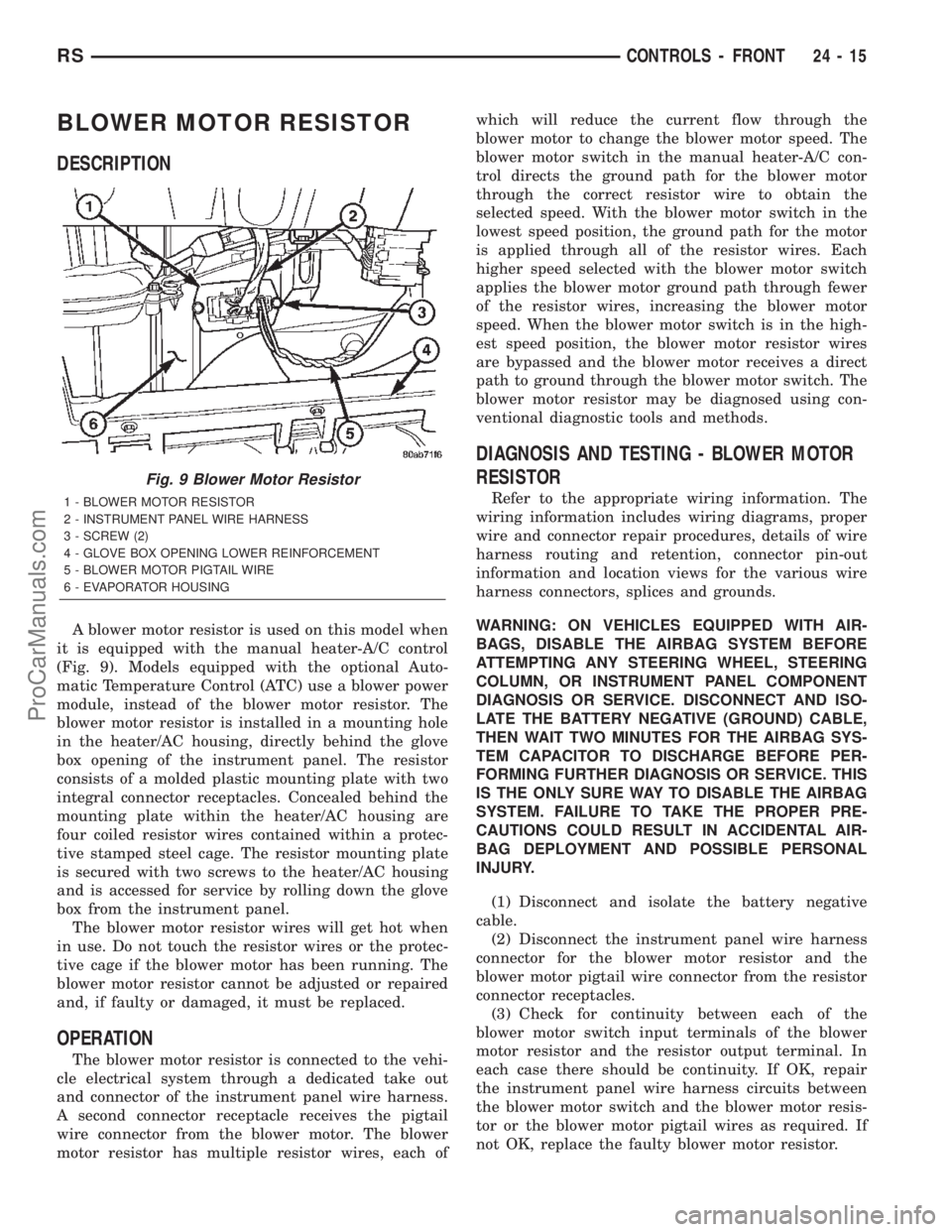
A blower motor resistor is used on this model when
it is equipped with the manual heater-A/C control
(Fig. 9). Models equipped with the optional Auto-
matic Temperature Control (ATC) use a blower power
module, instead of the blower motor resistor. The
blower motor resistor is installed in a mounting hole
in the heater/AC housing, directly behind the glove
box opening of the instrument panel. The resistor
consists of a molded plastic mounting plate with two
integral connector receptacles. Concealed behind the
mounting plate within the heater/AC housing are
four coiled resistor wires contained within a protec-
tive stamped steel cage. The resistor mounting plate
is secured with two screws to the heater/AC housing
and is accessed for service by rolling down the glove
box from the instrument panel.
The blower motor resistor wires will get hot when
in use. Do not touch the resistor wires or the protec-
tive cage if the blower motor has been running. The
blower motor resistor cannot be adjusted or repaired
and, if faulty or damaged, it must be replaced.
OPERATION
The blower motor resistor is connected to the vehi-
cle electrical system through a dedicated take out
and connector of the instrument panel wire harness.
A second connector receptacle receives the pigtail
wire connector from the blower motor. The blower
motor resistor has multiple resistor wires, each ofwhich will reduce the current flow through the
blower motor to change the blower motor speed. The
blower motor switch in the manual heater-A/C con-
trol directs the ground path for the blower motor
through the correct resistor wire to obtain the
selected speed. With the blower motor switch in the
lowest speed position, the ground path for the motor
is applied through all of the resistor wires. Each
higher speed selected with the blower motor switch
applies the blower motor ground path through fewer
of the resistor wires, increasing the blower motor
speed. When the blower motor switch is in the high-
est speed position, the blower motor resistor wires
are bypassed and the blower motor receives a direct
path to ground through the blower motor switch. The
blower motor resistor may be diagnosed using con-
ventional diagnostic tools and methods.
DIAGNOSIS AND TESTING - BLOWER MOTOR
RESISTOR
Refer to the appropriate wiring information. The
wiring information includes wiring diagrams, proper
wire and connector repair procedures, details of wire
harness routing and retention, connector pin-out
information and location views for the various wire
harness connectors, splices and grounds.
WARNING: ON VEHICLES EQUIPPED WITH AIR-
BAGS, DISABLE THE AIRBAG SYSTEM BEFORE
ATTEMPTING ANY STEERING WHEEL, STEERING
COLUMN, OR INSTRUMENT PANEL COMPONENT
DIAGNOSIS OR SERVICE. DISCONNECT AND ISO-
LATE THE BATTERY NEGATIVE (GROUND) CABLE,
THEN WAIT TWO MINUTES FOR THE AIRBAG SYS-
TEM CAPACITOR TO DISCHARGE BEFORE PER-
FORMING FURTHER DIAGNOSIS OR SERVICE. THIS
IS THE ONLY SURE WAY TO DISABLE THE AIRBAG
SYSTEM. FAILURE TO TAKE THE PROPER PRE-
CAUTIONS COULD RESULT IN ACCIDENTAL AIR-
BAG DEPLOYMENT AND POSSIBLE PERSONAL
INJURY.
(1) Disconnect and isolate the battery negative
cable.
(2) Disconnect the instrument panel wire harness
connector for the blower motor resistor and the
blower motor pigtail wire connector from the resistor
connector receptacles.
(3) Check for continuity between each of the
blower motor switch input terminals of the blower
motor resistor and the resistor output terminal. In
each case there should be continuity. If OK, repair
the instrument panel wire harness circuits between
the blower motor switch and the blower motor resis-
tor or the blower motor pigtail wires as required. If
not OK, replace the faulty blower motor resistor.
Fig. 9 Blower Motor Resistor
1 - BLOWER MOTOR RESISTOR
2 - INSTRUMENT PANEL WIRE HARNESS
3 - SCREW (2)
4 - GLOVE BOX OPENING LOWER REINFORCEMENT
5 - BLOWER MOTOR PIGTAIL WIRE
6 - EVAPORATOR HOUSING
RSCONTROLS - FRONT24-15
ProCarManuals.com
Page 2260 of 2399
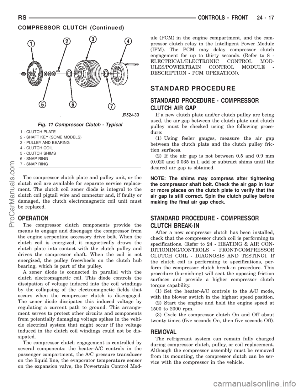
The compressor clutch plate and pulley unit, or the
clutch coil are available for separate service replace-
ment. The clutch coil zener diode is integral to the
clutch coil pigtail wire and connector and, if faulty or
damaged, the clutch electromagnetic coil unit must
be replaced.
OPERATION
The compressor clutch components provide the
means to engage and disengage the compressor from
the engine serpentine accessory drive belt. When the
clutch coil is energized, it magnetically draws the
clutch plate into contact with the clutch pulley and
drives the compressor shaft. When the coil is not
energized, the pulley freewheels on the clutch hub
bearing, which is part of the pulley.
A zener diode is connected in parallel with the
clutch electromagnetic coil. This diode controls the
dissipation of voltage induced into the coil windings
by the collapsing of the electromagnetic fields that
occurs when the compressor clutch is disengaged.
The zener diode dissipates this induced voltage by
regulating a current path to ground. This arrange-
ment serves to protect other circuits and components
from potentially damaging voltage spikes in the vehi-
cle electrical system that might occur if the voltage
induced in the clutch coil windings could not be dis-
sipated.
The compressor clutch engagement is controlled by
several components: the heater-A/C controls in the
passenger compartment, the A/C pressure transducer
on the liquid line, the evaporator temperature sensor
on the expansion valve, the Powertrain Control Mod-ule (PCM) in the engine compartment, and the com-
pressor clutch relay in the Intelligent Power Module
(IPM). The PCM may delay compressor clutch
engagement for up to thirty seconds. (Refer to 8 -
ELECTRICAL/ELECTRONIC CONTROL MOD-
ULES/POWERTRAIN CONTROL MODULE -
DESCRIPTION - PCM OPERATION).
STANDARD PROCEDURE
STANDARD PROCEDURE - COMPRESSOR
CLUTCH AIR GAP
If a new clutch plate and/or clutch pulley are being
used, the air gap between the clutch plate and clutch
pulley must be checked using the following proce-
dure:
(1) Using feeler gauges, measure the air gap
between the clutch plate and the clutch pulley fric-
tion surfaces.
(2) If the air gap is not between 0.5 and 0.9 mm
(0.020 and 0.035 in.), add or subtract shims until the
desired air gap is obtained.
NOTE: The shims may compress after tightening
the compressor shaft bolt. Check the air gap in four
or more places on the clutch plate to verify that the
air gap is still correct. Spin the clutch pulley before
making the final air gap check.
STANDARD PROCEDURE - COMPRESSOR
CLUTCH BREAK-IN
After a new compressor clutch has been installed,
check that the compressor clutch coil is performing to
specifications. (Refer to 24 - HEATING & AIR CON-
DITIONING/CONTROLS - FRONT/COMPRESSOR
CLUTCH COIL - DIAGNOSIS AND TESTING). If
the clutch coil is performing to specifications, per-
form the compressor clutch break-in procedure. This
procedure (burnishing) will seat the opposing friction
surfaces and provide a higher compressor clutch
torque capability.
(1) Set the heater-A/C controls to the A/C mode,
with the blower switch in the highest speed position.
(2) Start the engine and hold the engine speed at
1500 to 2000 rpm.
(3) Cycle the compressor clutch On and Off about
twenty times (five seconds On, then five seconds Off).
REMOVAL
The refrigerant system can remain fully charged
during compressor clutch, pulley, or coil replacement.
Although the compressor assembly must be removed
from its mounting, the compressor clutch can be ser-
vice with the compressor in the vehicle.
Fig. 11 Compressor Clutch - Typical
1 - CLUTCH PLATE
2 - SHAFT KEY (SOME MODELS)
3 - PULLEY AND BEARING
4 - CLUTCH COIL
5 - CLUTCH SHIMS
6 - SNAP RING
7 - SNAP RING
RSCONTROLS - FRONT24-17
COMPRESSOR CLUTCH (Continued)
ProCarManuals.com