2002 CHRYSLER CARAVAN tow
[x] Cancel search: towPage 2045 of 2399
(6) Disengage rubber grommet cable insulator
from hole in dash panel.
(7) Attach a suitable length of mechanic's wire to
latch end of cable to assist cable installation.
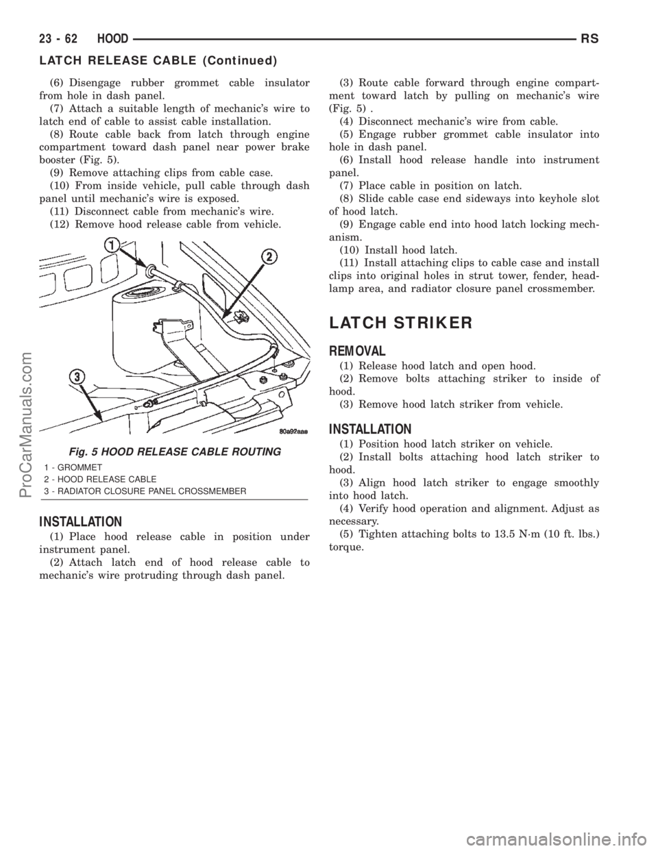
(8) Route cable back from latch through engine
compartment toward dash panel near power brake
booster (Fig. 5).
(9) Remove attaching clips from cable case.
(10) From inside vehicle, pull cable through dash
panel until mechanic's wire is exposed.
(11) Disconnect cable from mechanic's wire.
(12) Remove hood release cable from vehicle.
INSTALLATION
(1) Place hood release cable in position under
instrument panel.
(2) Attach latch end of hood release cable to
mechanic's wire protruding through dash panel.(3) Route cable forward through engine compart-
ment toward latch by pulling on mechanic's wire
(Fig. 5) .
(4) Disconnect mechanic's wire from cable.
(5) Engage rubber grommet cable insulator into
hole in dash panel.
(6) Install hood release handle into instrument
panel.
(7) Place cable in position on latch.
(8) Slide cable case end sideways into keyhole slot
of hood latch.
(9) Engage cable end into hood latch locking mech-
anism.
(10) Install hood latch.
(11) Install attaching clips to cable case and install
clips into original holes in strut tower, fender, head-
lamp area, and radiator closure panel crossmember.
LATCH STRIKER
REMOVAL
(1) Release hood latch and open hood.
(2) Remove bolts attaching striker to inside of
hood.
(3) Remove hood latch striker from vehicle.
INSTALLATION
(1) Position hood latch striker on vehicle.
(2) Install bolts attaching hood latch striker to
hood.
(3) Align hood latch striker to engage smoothly
into hood latch.
(4) Verify hood operation and alignment. Adjust as
necessary.
(5) Tighten attaching bolts to 13.5 N´m (10 ft. lbs.)
torque.Fig. 5 HOOD RELEASE CABLE ROUTING
1 - GROMMET
2 - HOOD RELEASE CABLE
3 - RADIATOR CLOSURE PANEL CROSSMEMBER
23 - 62 HOODRS
LATCH RELEASE CABLE (Continued)
ProCarManuals.com
Page 2050 of 2399
INSTALLATION
(1) With the help of an assistant place the instru-
ment panel into vehicle on roll down bolts. As you
roll the instrument panel up, lift the instrument
panel up so the duct work does not bind or bend and
you can set it down on the HVAC housing to get the
proper seal at the distribution duct. Get one bolt
started in the dash panel.
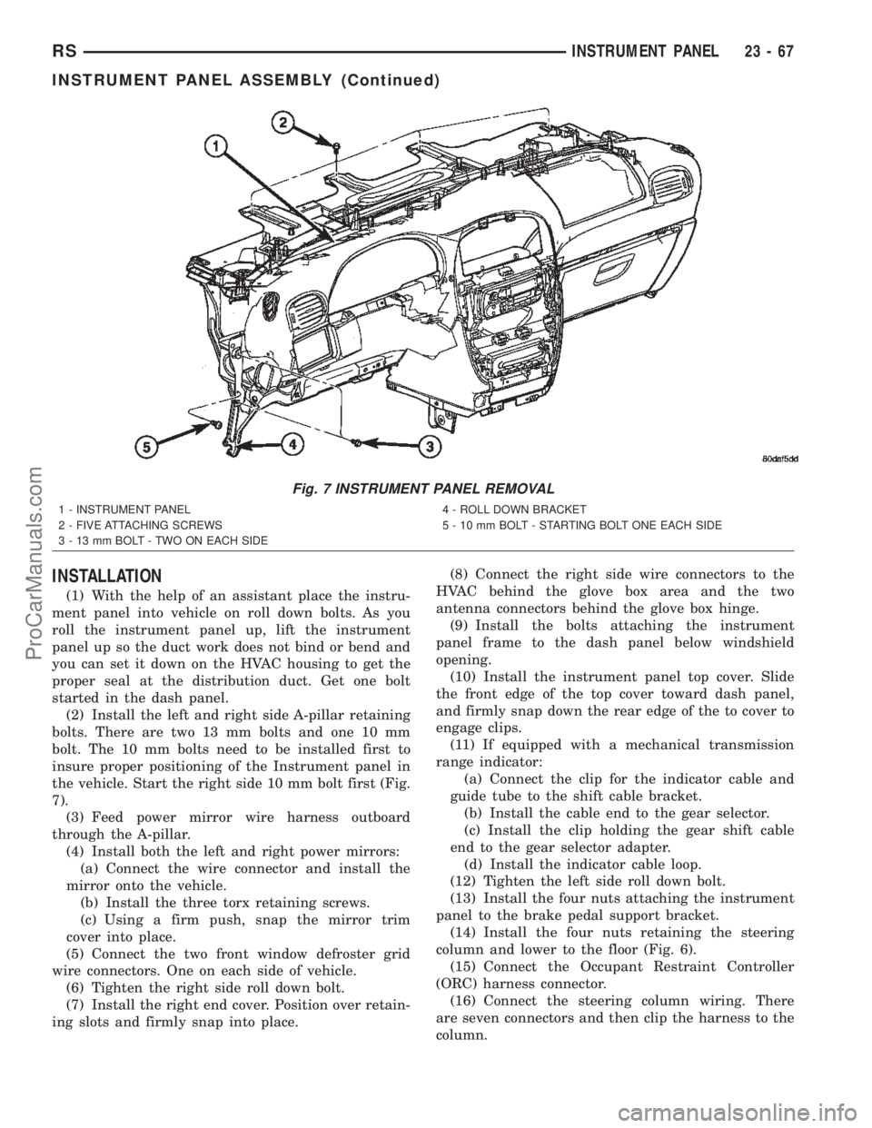
(2) Install the left and right side A-pillar retaining
bolts. There are two 13 mm bolts and one 10 mm
bolt. The 10 mm bolts need to be installed first to
insure proper positioning of the Instrument panel in
the vehicle. Start the right side 10 mm bolt first (Fig.
7).
(3) Feed power mirror wire harness outboard
through the A-pillar.
(4) Install both the left and right power mirrors:
(a) Connect the wire connector and install the
mirror onto the vehicle.
(b) Install the three torx retaining screws.
(c) Using a firm push, snap the mirror trim
cover into place.
(5) Connect the two front window defroster grid
wire connectors. One on each side of vehicle.
(6) Tighten the right side roll down bolt.
(7) Install the right end cover. Position over retain-
ing slots and firmly snap into place.(8) Connect the right side wire connectors to the
HVAC behind the glove box area and the two
antenna connectors behind the glove box hinge.
(9) Install the bolts attaching the instrument
panel frame to the dash panel below windshield
opening.
(10) Install the instrument panel top cover. Slide
the front edge of the top cover toward dash panel,
and firmly snap down the rear edge of the to cover to
engage clips.
(11) If equipped with a mechanical transmission
range indicator:
(a) Connect the clip for the indicator cable and
guide tube to the shift cable bracket.
(b) Install the cable end to the gear selector.
(c) Install the clip holding the gear shift cable
end to the gear selector adapter.
(d) Install the indicator cable loop.
(12) Tighten the left side roll down bolt.
(13) Install the four nuts attaching the instrument
panel to the brake pedal support bracket.
(14) Install the four nuts retaining the steering
column and lower to the floor (Fig. 6).
(15) Connect the Occupant Restraint Controller
(ORC) harness connector.
(16) Connect the steering column wiring. There
are seven connectors and then clip the harness to the
column.
Fig. 7 INSTRUMENT PANEL REMOVAL
1 - INSTRUMENT PANEL
2 - FIVE ATTACHING SCREWS
3 - 13 mm BOLT - TWO ON EACH SIDE4 - ROLL DOWN BRACKET
5 - 10 mm BOLT - STARTING BOLT ONE EACH SIDE
RSINSTRUMENT PANEL23-67
INSTRUMENT PANEL ASSEMBLY (Continued)
ProCarManuals.com
Page 2058 of 2399
(13) Remove push pin fasteners attaching carpet to
floor in front seat and rear area.
(14) Roll carpet from under instrument panel to
center of sliding door.
(15) Roll and fold carpet forward away from rear
door opening.
(16) Extract carpet through sliding door opening
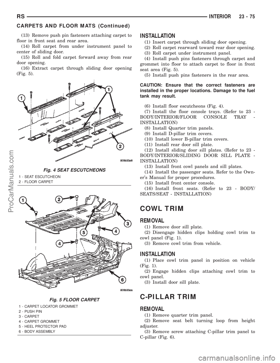
(Fig. 5).INSTALLATION
(1) Insert carpet through sliding door opening.
(2) Roll carpet rearward toward rear door opening.
(3) Roll carpet under instrument panel.
(4) Install push pins fasteners through carpet and
grommet into floor to attach carpet to floor in front
seat area (Fig. 5).
(5) Install push pins fasteners in the rear area.
CAUTION: Ensure that the correct fasteners are
installed in the proper locations. Damage to the fuel
tank may result.
(6) Install floor escutcheons (Fig. 4).
(7) Install the floor console trays. (Refer to 23 -
BODY/INTERIOR/FLOOR CONSOLE TRAY -
INSTALLATION)
(8) Install Quarter trim panels.
(9) Install D-pillar trim covers.
(10) Install lower B-pillar trim covers.
(11) Install rear door sill plate.
(12) Install sliding door sill plates. (Refer to 23 -
BODY/INTERIOR/SLIDING DOOR SILL PLATE -
INSTALLATION)
(13) Install front cowl panels and sill plates.
(14) Install the passenger seats. Refer to the Own-
er's Manual for proper procedures.
(15) Install front center console.
(16) Install front seats. (Refer to 23 - BODY/
SEATS/SEAT - INSTALLATION)
COWL TRIM
REMOVAL
(1) Remove door sill plate.
(2) Disengage hidden clips holding cowl trim to
cowl panel (Fig. 1).
(3) Remove cowl trim from vehicle.
INSTALLATION
(1) Place cowl trim panel in position on vehicle
(Fig. 1).
(2) Engage hidden clips attaching cowl trim to
cowl panel.
(3) Install door sill plate.
C-PILLAR TRIM
REMOVAL
(1) Remove quarter trim panel.
(2) Remove seat belt turning loop from height
adjuster.
(3) Remove screw attaching C-pillar trim panel to
C-pillar (Fig. 6).
Fig. 4 SEAT ESCUTCHEONS
1 - SEAT ESCUTCHEON
2 - FLOOR CARPET
Fig. 5 FLOOR CARPET
1 - CARPET LOCATOR GROMMET
2 - PUSH PIN
3 - CARPET
4 - CARPET GROMMET
5 - HEEL PROTECTOR PAD
6 - BODY ASSEMBLY
RSINTERIOR23-75
CARPETS AND FLOOR MATS (Continued)
ProCarManuals.com
Page 2070 of 2399

INSTALLATION
INSTALLATION
(1) Place child restraint seat module in position on
seat back (Fig. 4).
(2) Position seat back hinge interlock lever over
the top of the outboard child restraint seat hinge
(Fig. 5).
(3) Install screws attaching child restraint seat
module hinges to seat back frame lower rail (Fig. 1).
(4) Install screws attaching top of module to seat
back frame upper rail (Fig. 3). Tighten nuts to 7 N´m
(62 in. lbs.) torque.(5) Install push in fasteners attaching upper bol-
ster to child restraint seat module (Fig. 2).
(6) Return seat back to folded position.
(7) Install seat back cover.
(8) Verify child restraint seat operation.
SYNCHRONIZING CABLE ADJUSTMENT
NOTE:
Bench seats equipped with child restraint seats
have an interlock feature that will not allow the seat
back to fold forward with the child seat open.
If the seat back hinges do not release at the same
time the synchronizing cable must be adjusted.
(1) Remove seat from vehicle. Refer to Owner's
Manual for proper procedures.
(2) Disengage cable from the recline mechanism by
pulling the cable end toward the front of the seat
(Fig. 6).
(3) Pull U-shaped locking tab on self-adjusting
mehcanism to disengage auto-adjust feature.
(4) Reattach self-adjusting mechanism, pulling
against spring load to tighten cable.
(5) Press locking tab onto the adjusting mecha-
nism to lock into place.
Fig. 4 CHILD RESTRAINT SEAT MODULE
1 - 1ST REAR SEAT BACK
2 - CHILD RESTRAINT SEAT MODULE
3 - SEAT BACK HINGE INTERLOCK LEVER
Fig. 5 INTERLOCK LEVER
1 - CHILD RESTRAINT SEAT HINGE
2 - SEAT BACK HINGE INTERLOCK LEVER
3 - 1ST REAR SEAT BACK
4 - SEAT BACK FRAME RAIL
RSSEATS23-87
CHILD SEAT MODULE (Continued)
ProCarManuals.com
Page 2076 of 2399
(4) If equipped, open stowage bin to access front
pan bolts.
(5) Remove bolts attaching seat cushion pan to
seat track.
(6) Disconnect wire connectors, if equipment.
(7) Remove seat cushion from seat.
(8) Disengage J-strap retainers holding seat cover
to cushion.
(9) Remove seat cushion pan from cover and pad.
INSTALLATION
(1) Place seat cushion cover in position on seat
cushion.
(2) Engage J-strap retainers to hold seat cover to
cushion.
(3) Place seat cushion in position on seat.
(4) Connect wire connectors, if equipment.
(5) Install bolts attaching seat cushion to seat
track. Tighten bolts to 28.5 N´m (21 ft. lbs.) torque.
(6) If equipped, close stowage bin.
(7) Install seat track front and rear covers, if
equipped. (Refer to 23 - BODY/SEATS/SEAT TRACK
REAR COVER - INSTALLATION) and (Refer to 23 -
BODY/SEATS/SEAT TRACK FRONT COVER -
INSTALLATION)
(8) Install the quad seat side shield and cup holder
if equipped. (Refer to 23 - BODY/SEATS/QUAD
BUCKET SEAT SIDE SHIELD/CUP HOLDER -
INSTALLATION) and (Refer to 23 - BODY/SEATS/
QUAD BUCKET SEAT SIDE SHIELD - NO CUP
HOLDER - INSTALLATION)
(9) Install seat cushion side covers. (Refer to 23 -
BODY/SEATS/FRONT SEAT CUSHION SIDE
COVER - INSTALLATION)
FRONT SEAT CUSHION SIDE
COVER
REMOVAL
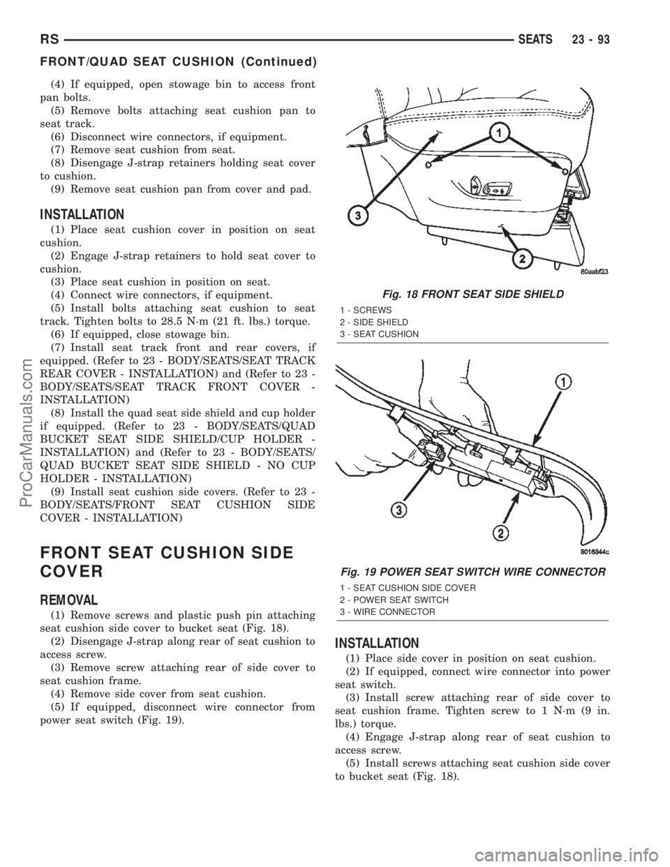
(1) Remove screws and plastic push pin attaching
seat cushion side cover to bucket seat (Fig. 18).
(2) Disengage J-strap along rear of seat cushion to
access screw.
(3) Remove screw attaching rear of side cover to
seat cushion frame.
(4) Remove side cover from seat cushion.
(5) If equipped, disconnect wire connector from
power seat switch (Fig. 19).
INSTALLATION
(1) Place side cover in position on seat cushion.
(2) If equipped, connect wire connector into power
seat switch.
(3) Install screw attaching rear of side cover to
seat cushion frame. Tighten screw to 1 N´m (9 in.
lbs.) torque.
(4) Engage J-strap along rear of seat cushion to
access screw.
(5) Install screws attaching seat cushion side cover
to bucket seat (Fig. 18).
Fig. 18 FRONT SEAT SIDE SHIELD
1 - SCREWS
2 - SIDE SHIELD
3 - SEAT CUSHION
Fig. 19 POWER SEAT SWITCH WIRE CONNECTOR
1 - SEAT CUSHION SIDE COVER
2 - POWER SEAT SWITCH
3 - WIRE CONNECTOR
RSSEATS23-93
FRONT/QUAD SEAT CUSHION (Continued)
ProCarManuals.com
Page 2085 of 2399
(3) Engage synchronizing cable housing into seat
back hinge.
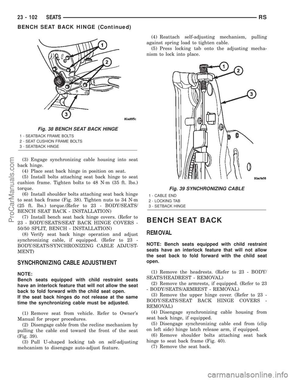
(4) Place seat back hinge in position on seat.
(5) Install bolts attaching seat back hinge to seat
cushion frame. Tighten bolts to 48 N´m (35 ft. lbs.)
torque.
(6) Install shoulder bolts attaching seat back hinge
to seat back frame (Fig. 38). Tighten nuts to 34 N´m
(25 ft. lbs.) torque.(Refer to 23 - BODY/SEATS/
BENCH SEAT BACK - INSTALLATION)
(7) Install bench seat back hinge covers. (Refer to
23 - BODY/SEATS/SEAT BACK HINGE COVERS -
50/50 SPLIT, BENCH - INSTALLATION)
(8) Verify seat back hinge operation and adjust
synchronizing cable, if equipped. (Refer to 23 -
BODY/SEATS/SYNCHRONIZING CABLE ADJUST-
MENT)
SYNCHRONIZING CABLE ADJUSTMENT
NOTE:
Bench seats equipped with child restraint seats
have an interlock feature that will not allow the seat
back to fold forward with the child seat open.
If the seat back hinges do not release at the same
time the synchronizing cable must be adjusted.
(1) Remove seat from vehicle. Refer to Owner's
Manual for proper procedures.
(2) Disengage cable from the recline mechanism by
pulling the cable end toward the front of the seat
(Fig. 39).
(3) Pull U-shaped locking tab on self-adjusting
mehcanism to disengage auto-adjust feature.(4) Reattach self-adjusting mechanism, pulling
against spring load to tighten cable.
(5) Press locking tab onto the adjusting mecha-
nism to lock into place.
BENCH SEAT BACK
REMOVAL
NOTE: Bench seats equipped with child restraint
seats have an interlock feature that will not allow
the seat back to fold forward with the child seat
open.
(1) Remove the headrests. (Refer to 23 - BODY/
SEATS/HEADREST - REMOVAL)
(2) Remove the armrests, if equipped. (Refer to 23
- BODY/SEATS/ARMREST - REMOVAL)
(3) Remove the upper hinge cover. (Refer to 23 -
BODY/SEATS/SEAT BACK HINGE COVERS -
REMOVAL)
(4) Disengage synchronizing cable housing from
seat back hinge, if equipped.
(5) Disengage synchronizing cable end from (clip
on left side) hinge latch release arm, if equipped.
(6) Remove shoulder bolts attaching seat back
hinge to seat back frame (Fig. 40).
(7) Remove the seat back.
Fig. 38 BENCH SEAT BACK HINGE
1 - SEATBACK FRAME BOLTS
2 - SEAT CUSHION FRAME BOLTS
3 - SEATBACK HINGE
Fig. 39 SYNCHRONIZING CABLE
1 - CABLE END
2 - LOCKING TAB
3 - SETBACK HINGE
23 - 102 SEATSRS
BENCH SEAT BACK HINGE (Continued)
ProCarManuals.com
Page 2104 of 2399
SEALER LOCATIONS
SPECIFICATIONS
BODY SEALING LOCATIONS
INDEX
DESCRIPTION FIGURE
METHODS OF APPLYING AUTO BODY SEALANT 5
LOWER WINDSHIELD OPENING - RIGHT AND LEFT SIDES 6
COWL SIDE - LEFT AND RIGHT SIDES 7
SIDE QUARTER WINDSHIELD OPENING - LEFT AND RIGHT SIDES 8
UPPER WINDSHIELD A-PILLAR - LEFT AND RIGHT SIDES 9
ROOF TRACK C-PILLAR - LEFT AND RIGHT SIDES 10
SLIDING DOOR UPPER FLANGE SEAMS - LEFT AND RIGHT SIDES 11
QUARTER PANEL EXTERIOR AREA - LEFT AND RIGHT SIDES 12
LOWER REAR EXTERIOR CORNER PANELS - LEFT AND RIGHT SIDES 13
LOWER SILL LIFT GATE OPENING - LEFT AND RIGHT SIDES 14
C-PILLAR CAN - LEFT AND RIGHT SIDES 15
SHOCK TOWER AREA - LEFT AND RIGHT SIDES 16
OUTER SHOCK TOWER AREA - LEFT AND RIGHT SIDES 17
CROSS MEMBER SUPPORT - LEFT AND RIGHT SIDES 18
A & B PILLAR FLOOR PAN RISERS - LEFT AND RIGHT SIDES 19
REAR WHEEL HOUSE FLOOR PAN - LEFT AND RIGHT SIDES 20
REAR WHEELHOUSE TO FLOOR PAN - LEFT AND RIGHT SIDES 21
UPPER SLIDING DOOR FLANGE - LEFT AND RIGHT SIDES 22
UPPER LIFTGATE HINGE AREA - LEFT AND RIGHT SIDES 23
REAR BRACKET SUPPORT REAR HANGER - LEFT AND RIGHT SIDES 24
LIFTGATE PANEL OPENING - UNDERSIDE 25
D-PILLAR INSIDE SEAM - LEFT AND RIGHT SIDES 26
REAR TAIL LAMP AREA SEAMS - LEFT AND RIGHT SIDES 27
UPPER LIFTGATE PANEL SILL - LEFT AND RIGHT SIDES 28
FRONT WHEELHOUSE & SHOCK TOWER - LEFT AND RIGHT SIDES 29
REAR QUARTER WHEELHOUSE LIP & SEAT ANCHOR BOLT - LEFT AND RIGHT
SIDES30
TAILLAMP CAN - LEFT AND RIGHT SIDES 31
B-PILLAR AND SILL AREAS - LEFT AND RIGHT SIDES 32
FRONT FLOOR PAN & RISER 33
FLOOR PAN SEAMS - LEFT AND RIGHT SIDES 34
FLOOR PAN & REAR WHEELHOUSE AREA - LEFT AND RIGHT SIDES 35
FLOOR PAN SILL & D-PILLAR SEAMS - LEFT AND RIGHT SIDES 36
LEFT SIDE SEAT ANCHOR REINFORCEMENT - SHORT WHEEL BASE ONLY 37
UNDERBODY - LEFT AND RIGHT SIDES 38
RSBODY STRUCTURE23 - 121
ProCarManuals.com
Page 2112 of 2399
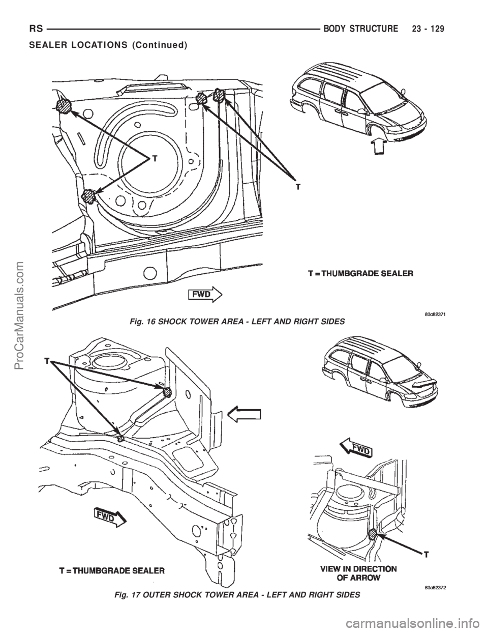
Fig. 16 SHOCK TOWER AREA - LEFT AND RIGHT SIDES
Fig. 17 OUTER SHOCK TOWER AREA - LEFT AND RIGHT SIDES
RSBODY STRUCTURE23 - 129
SEALER LOCATIONS (Continued)
ProCarManuals.com