2002 CHRYSLER CARAVAN cooling
[x] Cancel search: coolingPage 1408 of 2399
OIL PUMP
REMOVAL
REMOVAL
(1) Disconnect negative battery cable.
(2) Remove power steering belt (Refer to 7 -
COOLING/ACCESSORY DRIVE/DRIVE BELTS -
REMOVAL).
(3) Remove accessory drive belt (Refer to 7 -
COOLING/ACCESSORY DRIVE/DRIVE BELTS -
REMOVAL).
(4) Remove timing belt outer cover (Refer to 9 -
ENGINE/VALVE TIMING/TIMING BELT / CHAIN
COVER(S) - REMOVAL).
(5) Remove timing belt (Refer to 9 - ENGINE/
VALVE TIMING/TIMING BELT/CHAIN AND
SPROCKETS - REMOVAL).
(6) Remove timing belt inner cover (Refer to 9 -
ENGINE/VALVE TIMING/TIMING BELT / CHAIN
COVER(S) - REMOVAL).
(7) Remove front engine cover (Refer to 9 -
ENGINE/ENGINE BLOCK/ENGINE COVER -
REMOVAL).
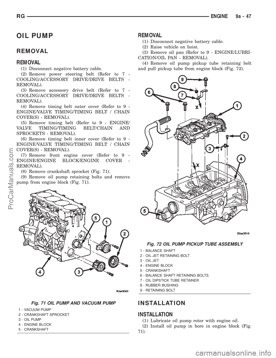
(8) Remove crankshaft sprocket (Fig. 71).
(9) Remove oil pump retaining bolts and remove
pump from engine block (Fig. 71).
REMOVAL
(1) Disconnect negative battery cable.
(2) Raise vehicle on hoist.
(3) Remove oil pan (Refer to 9 - ENGINE/LUBRI-
CATION/OIL PAN - REMOVAL).
(4) Remove oil pump pickup tube retaining bolt
and pull pickup tube from engine block (Fig. 72).
INSTALLATION
INSTALLATION
(1) Lubricate oil pump rotor with engine oil.
(2) Install oil pump in bore in engine block (Fig.
71).
Fig. 71 OIL PUMP AND VACUUM PUMP
1 - VACUUM PUMP
2 - CRANKSHAFT SPROCKET
3 - OIL PUMP
4 - ENGINE BLOCK
5 - CRANKSHAFT
Fig. 72 OIL PUMP PICKUP TUBE ASSEMBLY
1 - BALANCE SHAFT
2 - OIL JET RETAINING BOLT
3 - OIL JET
4 - ENGINE BLOCK
5 - CRANKSHAFT
6 - BALANCE SHAFT RETAINING BOLTS
7 - OIL DIPSTICK TUBE RETAINER
8 - RUBBER BUSHING
9 - RETAINING BOLT
RGENGINE9a-47
ProCarManuals.com
Page 1409 of 2399
(3) Install oil pump retaining bolts (Fig. 71).
Torque bolts to 10.8N´m.
(4) Install crankshaft sprocket (Fig. 71). Torque
bolts to 10.8N´m.
(5) Install front engine cover (Refer to 9 -
ENGINE/ENGINE BLOCK/ENGINE COVER -
INSTALLATION).
(6) Install timing belt inner cover (Refer to 9 -
ENGINE/VALVE TIMING/TIMING BELT / CHAIN
COVER(S) - INSTALLATION).
(7) Install timing belt (Refer to 9 - ENGINE/
VALVE TIMING/TIMING BELT/CHAIN AND
SPROCKETS - INSTALLATION) .
(8) Install timing belt outer cover (Refer to 9 -
ENGINE/VALVE TIMING/TIMING BELT / CHAIN
COVER(S) - INSTALLATION).
(9) Install accessory drive belt (Refer to 7 - COOL-
ING/ACCESSORY DRIVE/DRIVE BELTS - INSTAL-
LATION).
(10) Install power steering belt (Refer to 7 -
COOLING/ACCESSORY DRIVE/DRIVE BELTS -
INSTALLATION).
(11) Connect negative battery cable.
INSTALLATION
(1) Lubricate o-ring on oil pump pickup tube with
engine oil.
(2) Install pickup tube in engine block and install
retaining bolt (Fig. 72). Torque bolt to 32.4N´m.
(3) Install oil pan (Refer to 9 - ENGINE/LUBRI-
CATION/OIL PAN - INSTALLATION).
(4) Refill engine oil to proper level.
(5) Connect negative battery cable.
OIL PRESSURE SENSOR/
SWITCH
DESCRIPTION
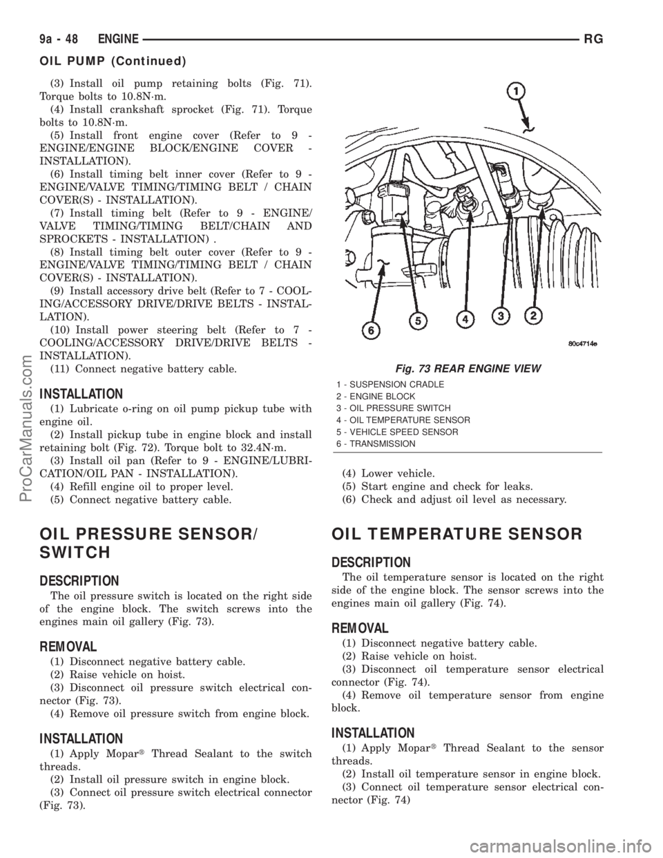
The oil pressure switch is located on the right side
of the engine block. The switch screws into the
engines main oil gallery (Fig. 73).
REMOVAL
(1) Disconnect negative battery cable.
(2) Raise vehicle on hoist.
(3) Disconnect oil pressure switch electrical con-
nector (Fig. 73).
(4) Remove oil pressure switch from engine block.
INSTALLATION
(1) Apply MopartThread Sealant to the switch
threads.
(2) Install oil pressure switch in engine block.
(3) Connect oil pressure switch electrical connector
(Fig. 73).(4) Lower vehicle.
(5) Start engine and check for leaks.
(6) Check and adjust oil level as necessary.
OIL TEMPERATURE SENSOR
DESCRIPTION
The oil temperature sensor is located on the right
side of the engine block. The sensor screws into the
engines main oil gallery (Fig. 74).
REMOVAL
(1) Disconnect negative battery cable.
(2) Raise vehicle on hoist.
(3) Disconnect oil temperature sensor electrical
connector (Fig. 74).
(4) Remove oil temperature sensor from engine
block.
INSTALLATION
(1) Apply MopartThread Sealant to the sensor
threads.
(2) Install oil temperature sensor in engine block.
(3) Connect oil temperature sensor electrical con-
nector (Fig. 74)
Fig. 73 REAR ENGINE VIEW
1 - SUSPENSION CRADLE
2 - ENGINE BLOCK
3 - OIL PRESSURE SWITCH
4 - OIL TEMPERATURE SENSOR
5 - VEHICLE SPEED SENSOR
6 - TRANSMISSION
9a - 48 ENGINERG
OIL PUMP (Continued)
ProCarManuals.com
Page 1411 of 2399
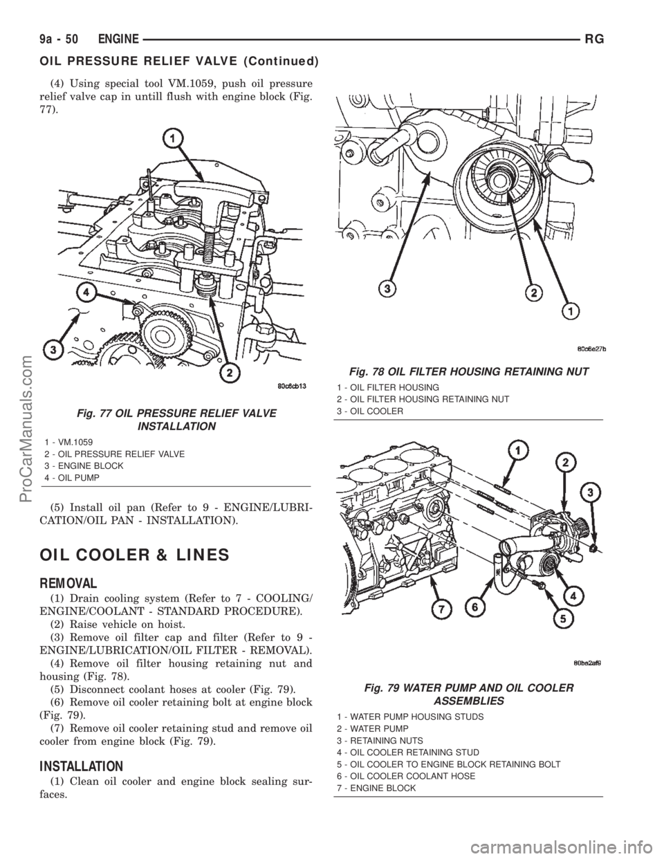
(4) Using special tool VM.1059, push oil pressure
relief valve cap in untill flush with engine block (Fig.
77).
(5) Install oil pan (Refer to 9 - ENGINE/LUBRI-
CATION/OIL PAN - INSTALLATION).
OIL COOLER & LINES
REMOVAL
(1) Drain cooling system (Refer to 7 - COOLING/
ENGINE/COOLANT - STANDARD PROCEDURE).
(2) Raise vehicle on hoist.
(3) Remove oil filter cap and filter (Refer to 9 -
ENGINE/LUBRICATION/OIL FILTER - REMOVAL).
(4) Remove oil filter housing retaining nut and
housing (Fig. 78).
(5) Disconnect coolant hoses at cooler (Fig. 79).
(6) Remove oil cooler retaining bolt at engine block
(Fig. 79).
(7) Remove oil cooler retaining stud and remove oil
cooler from engine block (Fig. 79).
INSTALLATION
(1) Clean oil cooler and engine block sealing sur-
faces.
Fig. 77 OIL PRESSURE RELIEF VALVE
INSTALLATION
1 - VM.1059
2 - OIL PRESSURE RELIEF VALVE
3 - ENGINE BLOCK
4 - OIL PUMP
Fig. 78 OIL FILTER HOUSING RETAINING NUT
1 - OIL FILTER HOUSING
2 - OIL FILTER HOUSING RETAINING NUT
3 - OIL COOLER
Fig. 79 WATER PUMP AND OIL COOLER
ASSEMBLIES
1 - WATER PUMP HOUSING STUDS
2 - WATER PUMP
3 - RETAINING NUTS
4 - OIL COOLER RETAINING STUD
5 - OIL COOLER TO ENGINE BLOCK RETAINING BOLT
6 - OIL COOLER COOLANT HOSE
7 - ENGINE BLOCK
9a - 50 ENGINERG
OIL PRESSURE RELIEF VALVE (Continued)
ProCarManuals.com
Page 1412 of 2399
(2) Install oil cooler, retaining bolt, and stud (Fig.
79). Torque retaining bolt to 47.1N´m and stud to
50N´m.
(3) Connect coolant hoses at cooler (Fig. 79).
(4) Install oil filter housing and retaining nut (Fig.
78). Torque retaining nut to 3.5 Kg.
(5) Install oil filter cartridge and oil filter cap
(Refer to 9 - ENGINE/LUBRICATION/OIL FILTER -
INSTALLATION).
(6) Lower vehicle.
(7) Refill cooling system (Refer to 7 - COOLING/
ENGINE/COOLANT - STANDARD PROCEDURE).
(8) Start engine and check for leaks.
(9) Check and adjust oil level as necessary.
OIL FILTER
DESCRIPTION
The oil filter used on this engine is a cartridge
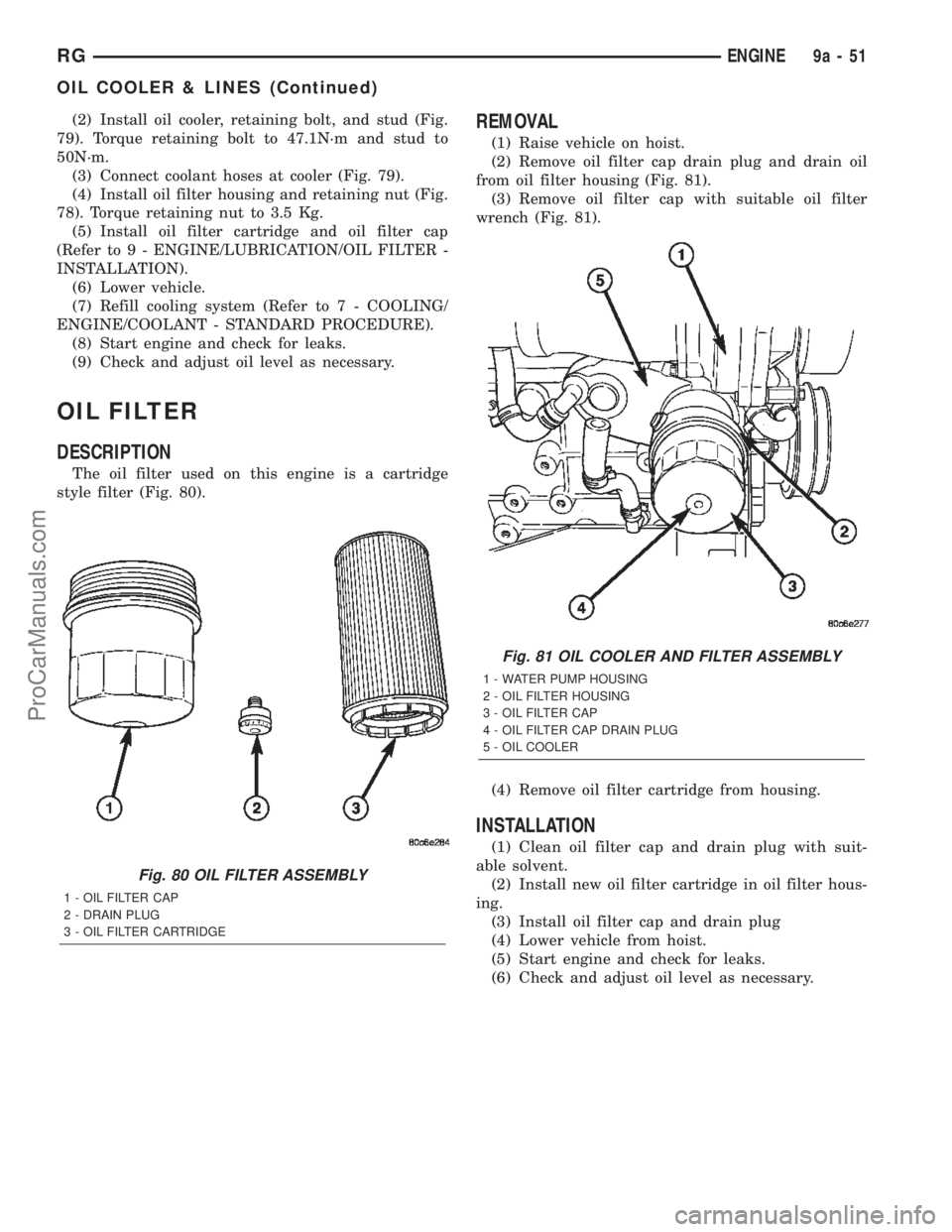
style filter (Fig. 80).
REMOVAL
(1) Raise vehicle on hoist.
(2) Remove oil filter cap drain plug and drain oil
from oil filter housing (Fig. 81).
(3) Remove oil filter cap with suitable oil filter
wrench (Fig. 81).
(4) Remove oil filter cartridge from housing.
INSTALLATION
(1) Clean oil filter cap and drain plug with suit-
able solvent.
(2) Install new oil filter cartridge in oil filter hous-
ing.
(3) Install oil filter cap and drain plug
(4) Lower vehicle from hoist.
(5) Start engine and check for leaks.
(6) Check and adjust oil level as necessary.
Fig. 80 OIL FILTER ASSEMBLY
1 - OIL FILTER CAP
2 - DRAIN PLUG
3 - OIL FILTER CARTRIDGE
Fig. 81 OIL COOLER AND FILTER ASSEMBLY
1 - WATER PUMP HOUSING
2 - OIL FILTER HOUSING
3 - OIL FILTER CAP
4 - OIL FILTER CAP DRAIN PLUG
5 - OIL COOLER
RGENGINE9a-51
OIL COOLER & LINES (Continued)
ProCarManuals.com
Page 1417 of 2399
(3) Install balance shaft assembly and retaining
bolts (Fig. 89). Torque bolts to 32.4N´m.
(4) Install oil pan (Refer to 9 - ENGINE/LUBRI-
CATION/OIL PAN - INSTALLATION).
(5) Refill engine oil to proper level.
(6) Connect negative battery cable.
TIMING BELT / CHAIN
COVER(S)
REMOVAL
REMOVAL - TIMING BELT OUTER COVER
(1) Disconnect negative battery cable.
(2) Remove engine cover (Refer to 9 - ENGINE -
REMOVAL).
(3) Remove air cleaner housing.
(4) Support engine and remove right engine mount
and bracket.
(5) Remove power steering belt (Refer to 7 -
COOLING/ACCESSORY DRIVE/DRIVE BELTS -
REMOVAL).
(6) Remove accessory drive belt (Refer to 7 -
COOLING/ACCESSORY DRIVE/DRIVE BELTS -
REMOVAL).
(7) Remove vibration damper (Refer to 9 -
ENGINE/ENGINE BLOCK/VIBRATION DAMPER -
REMOVAL).
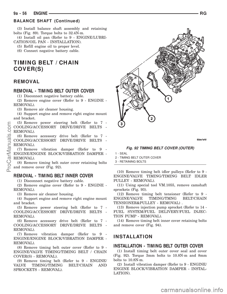
(8) Remove timing belt outer cover retaining bolts
and remove cover (Fig. 92).
REMOVAL - TIMING BELT INNER COVER
(1) Disconnect negative battery cable.
(2) Remove engine cover (Refer to 9 - ENGINE -
REMOVAL).
(3) Remove air cleaner housing.
(4) Support engine and remove right engine mount
and bracket.
(5) Remove power steering belt (Refer to 7 -
COOLING/ACCESSORY DRIVE/DRIVE BELTS -
REMOVAL).
(6) Remove accessory drive belt (Refer to 7 -
COOLING/ACCESSORY DRIVE/DRIVE BELTS -
REMOVAL).
(7) Remove vibration damper (Refer to 9 -
ENGINE/ENGINE BLOCK/VIBRATION DAMPER -
REMOVAL).
(8) Remove timing belt outer cover (Refer to 9 -
ENGINE/VALVE TIMING/TIMING BELT / CHAIN
COVER(S) - REMOVAL).
(9) Remove timing belt (Refer to 9 - ENGINE/
VALVE TIMING/TIMING BELT/CHAIN AND
SPROCKETS - REMOVAL).(10) Remove timing belt idler pulleys (Refer to 9 -
ENGINE/VALVE TIMING/TIMING BELT IDLER
PULLEY - REMOVAL).
(11) Using special tool VM.1055, remove camshaft
sprockets (Fig. 93).
(12) Remove timing belt tensioner (Refer to 9 -
ENGINE/VALVE TIMING/TMNG BELT/CHAIN
TENSIONER&PULLEY - REMOVAL) .
(13) Remove injection pump sprocket (Refer to 14 -
FUEL SYSTEM/FUEL DELIVERY/FUEL INJEC-
TION PUMP - REMOVAL).
(14) Remove timing belt inner cover retaining bolts
and remove cover (Fig. 94).
INSTALLATION
INSTALLATION - TIMING BELT OUTER COVER
(1) Install timing belt outer cover seal and cover
(Fig. 92). Torque 3mm bolts to 10.8N´m and 8mm
bolts to 10.8N´m.
(2) Install vibration damper (Refer to 9 - ENGINE/
ENGINE BLOCK/VIBRATION DAMPER - INSTAL-
LATION).
Fig. 92 TIMING BELT COVER (OUTER)
1 - SEAL
2 - TIMING BELT OUTER COVER
3 - RETAINING BOLTS
9a - 56 ENGINERG
BALANCE SHAFT (Continued)
ProCarManuals.com
Page 1419 of 2399
(9) Install vibration damper (Refer to 9 - ENGINE/
ENGINE BLOCK/VIBRATION DAMPER - INSTAL-
LATION).
(10) Install accessory drive belt (Refer to 7 -
COOLING/ACCESSORY DRIVE/DRIVE BELTS -
INSTALLATION).
(11) Install power steering belt (Refer to 7 - COOL-
ING/ACCESSORY DRIVE/DRIVE BELTS - INSTAL-
LATION).
(12) Install right engine mount assembly.
(13) Install air cleaner housing.
(14) Install engine cover (Refer to 9 - ENGINE -
INSTALLATION).
(15) Connect negative battery cable.
TIMING BELT IDLER PULLEY
REMOVAL
(1) Disconnect negative battery cable.
(2) Remove engine cover (Refer to 9 - ENGINE -
REMOVAL).
(3) Remove air cleaner housing.
(4) Support engine and remove right engine
mount.
(5) Remove power steering belt (Refer to 7 -
COOLING/ACCESSORY DRIVE/DRIVE BELTS -
REMOVAL).
(6) Remove accessory drive belt (Refer to 7 -
COOLING/ACCESSORY DRIVE/DRIVE BELTS -
REMOVAL).
(7) Remove vibration damper (Refer to 9 -
ENGINE/ENGINE BLOCK/VIBRATION DAMPER -
REMOVAL).
(8) Remove timing belt outer cover (Refer to 9 -
ENGINE/VALVE TIMING/TIMING BELT / CHAIN
COVER(S) - REMOVAL).
(9) Remove timing belt (Refer to 9 - ENGINE/
VALVE TIMING/TIMING BELT/CHAIN AND
SPROCKETS - REMOVAL).
NOTE: Idler pulley retaining bolts are LHD thread.
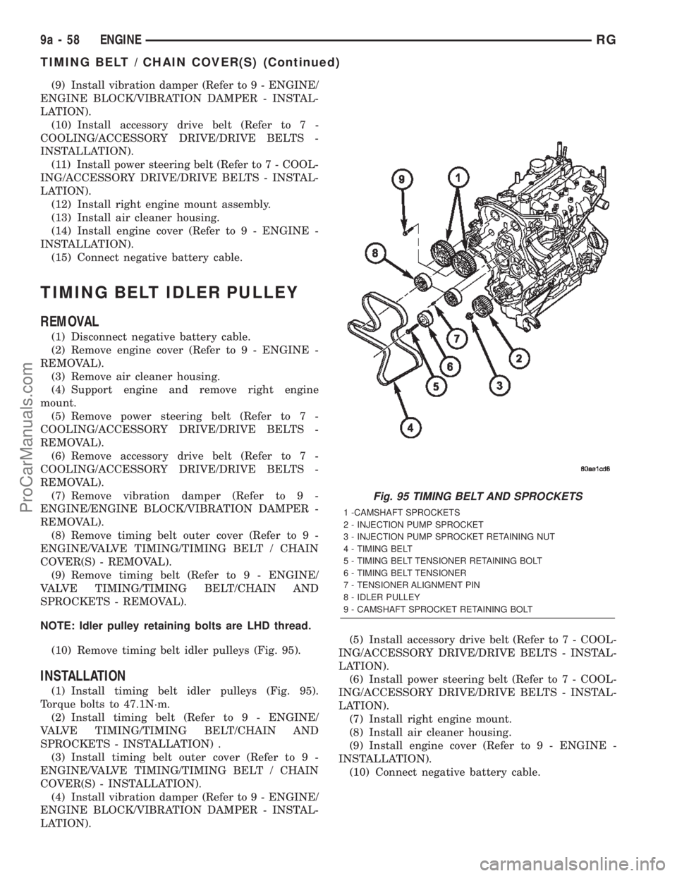
(10) Remove timing belt idler pulleys (Fig. 95).
INSTALLATION
(1) Install timing belt idler pulleys (Fig. 95).
Torque bolts to 47.1N´m.
(2) Install timing belt (Refer to 9 - ENGINE/
VALVE TIMING/TIMING BELT/CHAIN AND
SPROCKETS - INSTALLATION) .
(3) Install timing belt outer cover (Refer to 9 -
ENGINE/VALVE TIMING/TIMING BELT / CHAIN
COVER(S) - INSTALLATION).
(4) Install vibration damper (Refer to 9 - ENGINE/
ENGINE BLOCK/VIBRATION DAMPER - INSTAL-
LATION).(5) Install accessory drive belt (Refer to 7 - COOL-
ING/ACCESSORY DRIVE/DRIVE BELTS - INSTAL-
LATION).
(6) Install power steering belt (Refer to 7 - COOL-
ING/ACCESSORY DRIVE/DRIVE BELTS - INSTAL-
LATION).
(7) Install right engine mount.
(8) Install air cleaner housing.
(9) Install engine cover (Refer to 9 - ENGINE -
INSTALLATION).
(10) Connect negative battery cable.
Fig. 95 TIMING BELT AND SPROCKETS
1 -CAMSHAFT SPROCKETS
2 - INJECTION PUMP SPROCKET
3 - INJECTION PUMP SPROCKET RETAINING NUT
4 - TIMING BELT
5 - TIMING BELT TENSIONER RETAINING BOLT
6 - TIMING BELT TENSIONER
7 - TENSIONER ALIGNMENT PIN
8 - IDLER PULLEY
9 - CAMSHAFT SPROCKET RETAINING BOLT
9a - 58 ENGINERG
TIMING BELT / CHAIN COVER(S) (Continued)
ProCarManuals.com
Page 1420 of 2399
TMNG BELT/CHAIN
TENSIONER
REMOVAL
(1) Disconnect negative battery cable.
(2) Remove engine cover (Refer to 9 - ENGINE -
REMOVAL).
(3) Remove air cleaner housing.
(4) Support engine and remove right engine
mount.
(5) Remove power steering belt (Refer to 7 -
COOLING/ACCESSORY DRIVE/DRIVE BELTS -
REMOVAL).
(6) Remove accessory drive belt (Refer to 7 -
COOLING/ACCESSORY DRIVE/DRIVE BELTS -
REMOVAL).
(7) Remove vibration damper (Refer to 9 -
ENGINE/ENGINE BLOCK/VIBRATION DAMPER -
REMOVAL).
(8) Remove timing belt outer cover (Refer to 9 -
ENGINE/VALVE TIMING/TIMING BELT / CHAIN
COVER(S) - REMOVAL).
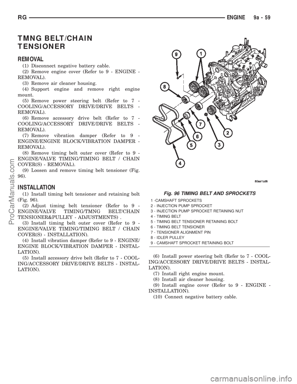
(9) Loosen and remove timing belt tensioner (Fig.
96).
INSTALLATION
(1) Install timing belt tensioner and retaining bolt
(Fig. 96).
(2) Adjust timing belt tensioner (Refer to 9 -
ENGINE/VALVE TIMING/TMNG BELT/CHAIN
TENSIONER&PULLEY - ADJUSTMENTS) .
(3) Install timing belt outer cover (Refer to 9 -
ENGINE/VALVE TIMING/TIMING BELT / CHAIN
COVER(S) - INSTALLATION).
(4) Install vibration damper (Refer to 9 - ENGINE/
ENGINE BLOCK/VIBRATION DAMPER - INSTAL-
LATION).
(5) Install accessory drive belt (Refer to 7 - COOL-
ING/ACCESSORY DRIVE/DRIVE BELTS - INSTAL-
LATION).(6) Install power steering belt (Refer to 7 - COOL-
ING/ACCESSORY DRIVE/DRIVE BELTS - INSTAL-
LATION).
(7) Install right engine mount.
(8) Install air cleaner housing.
(9) Install engine cover (Refer to 9 - ENGINE -
INSTALLATION).
(10) Connect negative battery cable.Fig. 96 TIMING BELT AND SPROCKETS
1 -CAMSHAFT SPROCKETS
2 - INJECTION PUMP SPROCKET
3 - INJECTION PUMP SPROCKET RETAINING NUT
4 - TIMING BELT
5 - TIMING BELT TENSIONER RETAINING BOLT
6 - TIMING BELT TENSIONER
7 - TENSIONER ALIGNMENT PIN
8 - IDLER PULLEY
9 - CAMSHAFT SPROCKET RETAINING BOLT
RGENGINE9a-59
ProCarManuals.com
Page 1421 of 2399
ADJUSTMENTS
ADJUSTMENT - TIMING BELT TENSIONER
(1) With timing belt outer cover removed and tim-
ing belt installed.
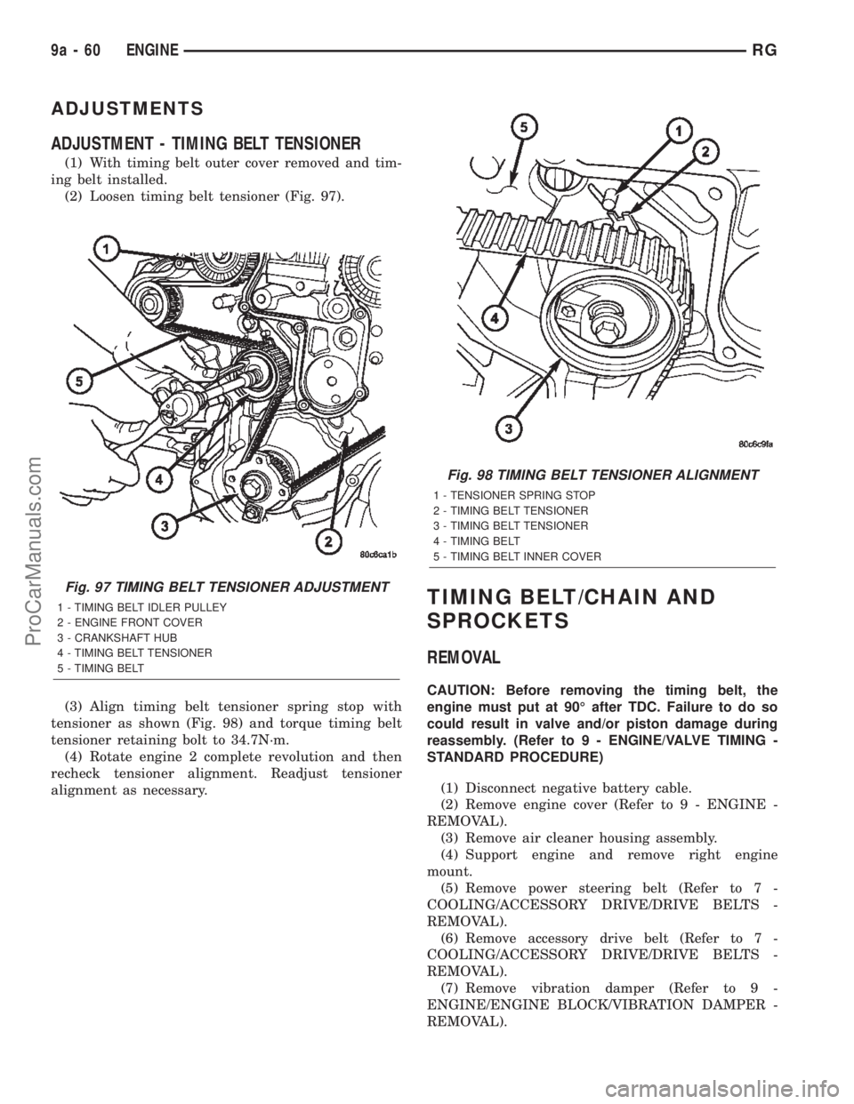
(2) Loosen timing belt tensioner (Fig. 97).
(3) Align timing belt tensioner spring stop with
tensioner as shown (Fig. 98) and torque timing belt
tensioner retaining bolt to 34.7N´m.
(4) Rotate engine 2 complete revolution and then
recheck tensioner alignment. Readjust tensioner
alignment as necessary.
TIMING BELT/CHAIN AND
SPROCKETS
REMOVAL
CAUTION: Before removing the timing belt, the
engine must put at 90É after TDC. Failure to do so
could result in valve and/or piston damage during
reassembly. (Refer to 9 - ENGINE/VALVE TIMING -
STANDARD PROCEDURE)
(1) Disconnect negative battery cable.
(2) Remove engine cover (Refer to 9 - ENGINE -
REMOVAL).
(3) Remove air cleaner housing assembly.
(4) Support engine and remove right engine
mount.
(5) Remove power steering belt (Refer to 7 -
COOLING/ACCESSORY DRIVE/DRIVE BELTS -
REMOVAL).
(6) Remove accessory drive belt (Refer to 7 -
COOLING/ACCESSORY DRIVE/DRIVE BELTS -
REMOVAL).
(7) Remove vibration damper (Refer to 9 -
ENGINE/ENGINE BLOCK/VIBRATION DAMPER -
REMOVAL).
Fig. 97 TIMING BELT TENSIONER ADJUSTMENT
1 - TIMING BELT IDLER PULLEY
2 - ENGINE FRONT COVER
3 - CRANKSHAFT HUB
4 - TIMING BELT TENSIONER
5 - TIMING BELT
Fig. 98 TIMING BELT TENSIONER ALIGNMENT
1 - TENSIONER SPRING STOP
2 - TIMING BELT TENSIONER
3 - TIMING BELT TENSIONER
4 - TIMING BELT
5 - TIMING BELT INNER COVER
9a - 60 ENGINERG
ProCarManuals.com