2002 CHRYSLER CARAVAN cooling
[x] Cancel search: coolingPage 1384 of 2399
CAUTION: Before removing the cylinder head cover/
intake manifold or timing belt the engine must put
at 90É after TDC. Failure to do so could result in
valve and/or piston damage during reassembly.
(Refer to 9 - ENGINE/VALVE TIMING - STANDARD
PROCEDURE)
(10) Remove timing belt outer cover (Refer to 9 -
ENGINE/VALVE TIMING/TIMING BELT / CHAIN
COVER(S) - REMOVAL).
(11) Remove timing belt (Refer to 9 - ENGINE/
VALVE TIMING/TIMING BELT/CHAIN AND
SPROCKETS - REMOVAL).
(12) Remove timing belt inner cover (Refer to 9 -
ENGINE/VALVE TIMING/TIMING BELT / CHAIN
COVER(S) - REMOVAL).
(13) Remove cylinder head cover/intake manifold
(Refer to 9 - ENGINE/CYLINDER HEAD/CYLIN-
DER HEAD COVER(S) - REMOVAL).
(14) With cylinder head cover/intake manifold on
work bench, remove plugs at rear of cylinder head
cover/intake manifold.
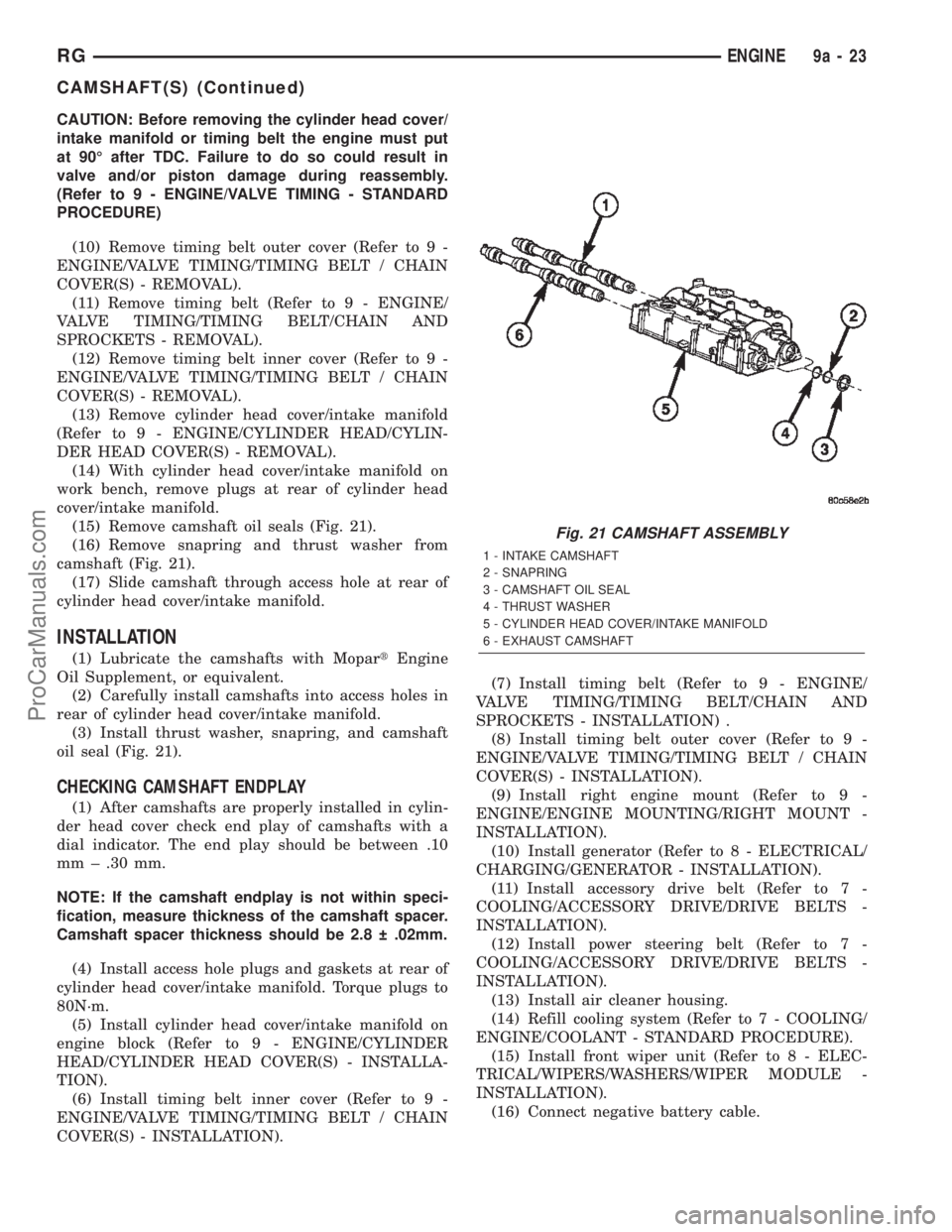
(15) Remove camshaft oil seals (Fig. 21).
(16) Remove snapring and thrust washer from
camshaft (Fig. 21).
(17) Slide camshaft through access hole at rear of
cylinder head cover/intake manifold.
INSTALLATION
(1) Lubricate the camshafts with MopartEngine
Oil Supplement, or equivalent.
(2) Carefully install camshafts into access holes in
rear of cylinder head cover/intake manifold.
(3) Install thrust washer, snapring, and camshaft
oil seal (Fig. 21).
CHECKING CAMSHAFT ENDPLAY
(1) After camshafts are properly installed in cylin-
der head cover check end play of camshafts with a
dial indicator. The end play should be between .10
mm ± .30 mm.
NOTE: If the camshaft endplay is not within speci-
fication, measure thickness of the camshaft spacer.
Camshaft spacer thickness should be 2.8 .02mm.
(4) Install access hole plugs and gaskets at rear of
cylinder head cover/intake manifold. Torque plugs to
80N´m.
(5) Install cylinder head cover/intake manifold on
engine block (Refer to 9 - ENGINE/CYLINDER
HEAD/CYLINDER HEAD COVER(S) - INSTALLA-
TION).
(6) Install timing belt inner cover (Refer to 9 -
ENGINE/VALVE TIMING/TIMING BELT / CHAIN
COVER(S) - INSTALLATION).(7) Install timing belt (Refer to 9 - ENGINE/
VALVE TIMING/TIMING BELT/CHAIN AND
SPROCKETS - INSTALLATION) .
(8) Install timing belt outer cover (Refer to 9 -
ENGINE/VALVE TIMING/TIMING BELT / CHAIN
COVER(S) - INSTALLATION).
(9) Install right engine mount (Refer to 9 -
ENGINE/ENGINE MOUNTING/RIGHT MOUNT -
INSTALLATION).
(10) Install generator (Refer to 8 - ELECTRICAL/
CHARGING/GENERATOR - INSTALLATION).
(11) Install accessory drive belt (Refer to 7 -
COOLING/ACCESSORY DRIVE/DRIVE BELTS -
INSTALLATION).
(12) Install power steering belt (Refer to 7 -
COOLING/ACCESSORY DRIVE/DRIVE BELTS -
INSTALLATION).
(13) Install air cleaner housing.
(14) Refill cooling system (Refer to 7 - COOLING/
ENGINE/COOLANT - STANDARD PROCEDURE).
(15) Install front wiper unit (Refer to 8 - ELEC-
TRICAL/WIPERS/WASHERS/WIPER MODULE -
INSTALLATION).
(16) Connect negative battery cable.
Fig. 21 CAMSHAFT ASSEMBLY
1 - INTAKE CAMSHAFT
2 - SNAPRING
3 - CAMSHAFT OIL SEAL
4 - THRUST WASHER
5 - CYLINDER HEAD COVER/INTAKE MANIFOLD
6 - EXHAUST CAMSHAFT
RGENGINE9a-23
CAMSHAFT(S) (Continued)
ProCarManuals.com
Page 1385 of 2399
CYLINDER HEAD COVER(S)
DESCRIPTION
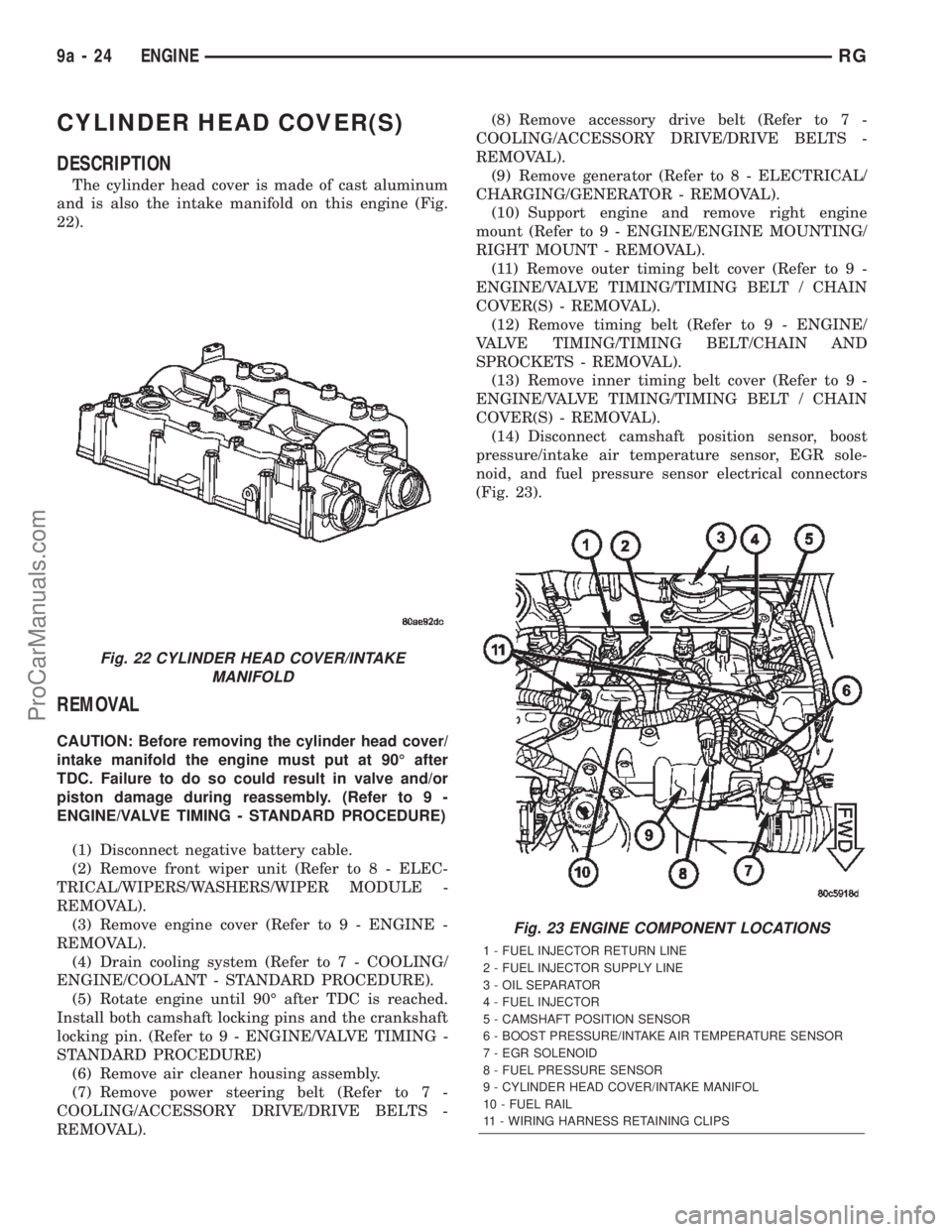
The cylinder head cover is made of cast aluminum
and is also the intake manifold on this engine (Fig.
22).
REMOVAL
CAUTION: Before removing the cylinder head cover/
intake manifold the engine must put at 90É after
TDC. Failure to do so could result in valve and/or
piston damage during reassembly. (Refer to 9 -
ENGINE/VALVE TIMING - STANDARD PROCEDURE)
(1) Disconnect negative battery cable.
(2) Remove front wiper unit (Refer to 8 - ELEC-
TRICAL/WIPERS/WASHERS/WIPER MODULE -
REMOVAL).
(3) Remove engine cover (Refer to 9 - ENGINE -
REMOVAL).
(4) Drain cooling system (Refer to 7 - COOLING/
ENGINE/COOLANT - STANDARD PROCEDURE).
(5) Rotate engine until 90É after TDC is reached.
Install both camshaft locking pins and the crankshaft
locking pin. (Refer to 9 - ENGINE/VALVE TIMING -
STANDARD PROCEDURE)
(6) Remove air cleaner housing assembly.
(7) Remove power steering belt (Refer to 7 -
COOLING/ACCESSORY DRIVE/DRIVE BELTS -
REMOVAL).(8) Remove accessory drive belt (Refer to 7 -
COOLING/ACCESSORY DRIVE/DRIVE BELTS -
REMOVAL).
(9) Remove generator (Refer to 8 - ELECTRICAL/
CHARGING/GENERATOR - REMOVAL).
(10) Support engine and remove right engine
mount (Refer to 9 - ENGINE/ENGINE MOUNTING/
RIGHT MOUNT - REMOVAL).
(11) Remove outer timing belt cover (Refer to 9 -
ENGINE/VALVE TIMING/TIMING BELT / CHAIN
COVER(S) - REMOVAL).
(12) Remove timing belt (Refer to 9 - ENGINE/
VALVE TIMING/TIMING BELT/CHAIN AND
SPROCKETS - REMOVAL).
(13) Remove inner timing belt cover (Refer to 9 -
ENGINE/VALVE TIMING/TIMING BELT / CHAIN
COVER(S) - REMOVAL).
(14) Disconnect camshaft position sensor, boost
pressure/intake air temperature sensor, EGR sole-
noid, and fuel pressure sensor electrical connectors
(Fig. 23).
Fig. 22 CYLINDER HEAD COVER/INTAKE
MANIFOLD
Fig. 23 ENGINE COMPONENT LOCATIONS
1 - FUEL INJECTOR RETURN LINE
2 - FUEL INJECTOR SUPPLY LINE
3 - OIL SEPARATOR
4 - FUEL INJECTOR
5 - CAMSHAFT POSITION SENSOR
6 - BOOST PRESSURE/INTAKE AIR TEMPERATURE SENSOR
7 - EGR SOLENOID
8 - FUEL PRESSURE SENSOR
9 - CYLINDER HEAD COVER/INTAKE MANIFOL
10 - FUEL RAIL
11 - WIRING HARNESS RETAINING CLIPS
9a - 24 ENGINERG
ProCarManuals.com
Page 1388 of 2399
(22) Install right engine mount (Refer to 9 -
ENGINE/ENGINE MOUNTING/RIGHT MOUNT -
INSTALLATION).
(23) Install generator (Refer to 8 - ELECTRICAL/
CHARGING/GENERATOR - INSTALLATION).
(24) Install accessory drive belt (Refer to 7 -
COOLING/ACCESSORY DRIVE/DRIVE BELTS -
INSTALLATION).
(25) Install power steering belt (Refer to 7 -
COOLING/ACCESSORY DRIVE/DRIVE BELTS -
INSTALLATION).
(26) Install air cleaner housing assembly.
(27) Remove crankshaft and both camshaft locking
pins (Refer to 9 - ENGINE/VALVE TIMING - STAN-
DARD PROCEDURE).
(28) Refill cooling system (Refer to 7 - COOLING/
ENGINE/COOLANT - STANDARD PROCEDURE).
(29) Install engine cover (Refer to 9 - ENGINE -
INSTALLATION).
(30) Install front wiper unit (Refer to 8 - ELEC-
TRICAL/WIPERS/WASHERS/WIPER MODULE -
INSTALLATION).
(31) Connect negative battery cable.
CAMSHAFT OIL SEAL(S)
REMOVAL
(1) Disconnect negative battery cable.
(2) Remove air cleaner housing assembly.
(3) Support engine and remove right engine mount
(Refer to 9 - ENGINE/ENGINE MOUNTING/RIGHT
MOUNT - REMOVAL).
(4) Remove outer timing belt cover (Refer to 9 -
ENGINE/VALVE TIMING/TIMING BELT / CHAIN
COVER(S) - REMOVAL).
WARNING: Before removing the timing belt the
engine must put at 90É after TDC. Failure to do so
could result in valve and/or piston damage during
reassembly. (Refer to 9 - ENGINE/VALVE TIMING -
STANDARD PROCEDURE)
(5) Remove timing belt (Refer to 9 - ENGINE/
VALVE TIMING/TIMING BELT/CHAIN AND
SPROCKETS - REMOVAL).
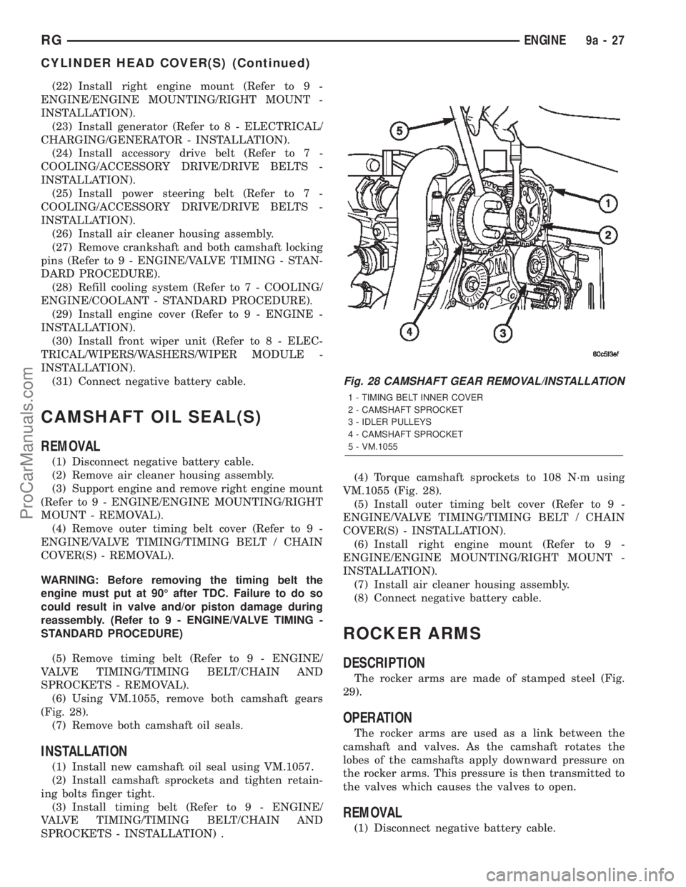
(6) Using VM.1055, remove both camshaft gears
(Fig. 28).
(7) Remove both camshaft oil seals.
INSTALLATION
(1) Install new camshaft oil seal using VM.1057.
(2) Install camshaft sprockets and tighten retain-
ing bolts finger tight.
(3) Install timing belt (Refer to 9 - ENGINE/
VALVE TIMING/TIMING BELT/CHAIN AND
SPROCKETS - INSTALLATION) .(4) Torque camshaft sprockets to 108 N´m using
VM.1055 (Fig. 28).
(5) Install outer timing belt cover (Refer to 9 -
ENGINE/VALVE TIMING/TIMING BELT / CHAIN
COVER(S) - INSTALLATION).
(6) Install right engine mount (Refer to 9 -
ENGINE/ENGINE MOUNTING/RIGHT MOUNT -
INSTALLATION).
(7) Install air cleaner housing assembly.
(8) Connect negative battery cable.
ROCKER ARMS
DESCRIPTION
The rocker arms are made of stamped steel (Fig.
29).
OPERATION
The rocker arms are used as a link between the
camshaft and valves. As the camshaft rotates the
lobes of the camshafts apply downward pressure on
the rocker arms. This pressure is then transmitted to
the valves which causes the valves to open.
REMOVAL
(1) Disconnect negative battery cable.
Fig. 28 CAMSHAFT GEAR REMOVAL/INSTALLATION
1 - TIMING BELT INNER COVER
2 - CAMSHAFT SPROCKET
3 - IDLER PULLEYS
4 - CAMSHAFT SPROCKET
5 - VM.1055
RGENGINE9a-27
CYLINDER HEAD COVER(S) (Continued)
ProCarManuals.com
Page 1396 of 2399
INTERNAL VACUUM PUMP
DESCRIPTION
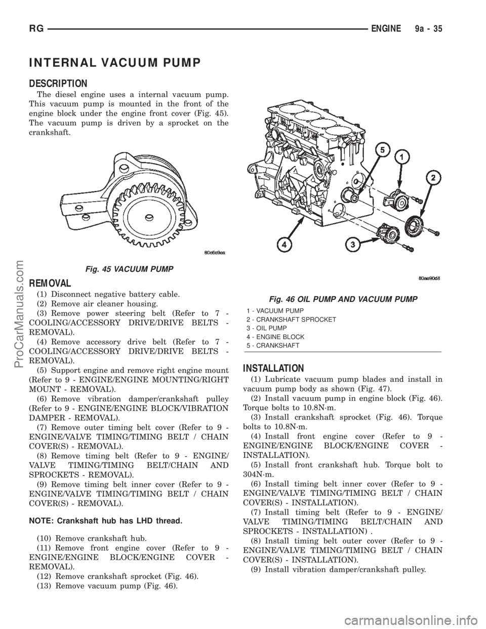
The diesel engine uses a internal vacuum pump.
This vacuum pump is mounted in the front of the
engine block under the engine front cover (Fig. 45).
The vacuum pump is driven by a sprocket on the
crankshaft.
REMOVAL
(1) Disconnect negative battery cable.
(2) Remove air cleaner housing.
(3) Remove power steering belt (Refer to 7 -
COOLING/ACCESSORY DRIVE/DRIVE BELTS -
REMOVAL).
(4) Remove accessory drive belt (Refer to 7 -
COOLING/ACCESSORY DRIVE/DRIVE BELTS -
REMOVAL).
(5) Support engine and remove right engine mount
(Refer to 9 - ENGINE/ENGINE MOUNTING/RIGHT
MOUNT - REMOVAL).
(6) Remove vibration damper/crankshaft pulley
(Refer to 9 - ENGINE/ENGINE BLOCK/VIBRATION
DAMPER - REMOVAL).
(7) Remove outer timing belt cover (Refer to 9 -
ENGINE/VALVE TIMING/TIMING BELT / CHAIN
COVER(S) - REMOVAL).
(8) Remove timing belt (Refer to 9 - ENGINE/
VALVE TIMING/TIMING BELT/CHAIN AND
SPROCKETS - REMOVAL).
(9) Remove timing belt inner cover (Refer to 9 -
ENGINE/VALVE TIMING/TIMING BELT / CHAIN
COVER(S) - REMOVAL).
NOTE: Crankshaft hub has LHD thread.
(10) Remove crankshaft hub.
(11) Remove front engine cover (Refer to 9 -
ENGINE/ENGINE BLOCK/ENGINE COVER -
REMOVAL).
(12) Remove crankshaft sprocket (Fig. 46).
(13) Remove vacuum pump (Fig. 46).
INSTALLATION
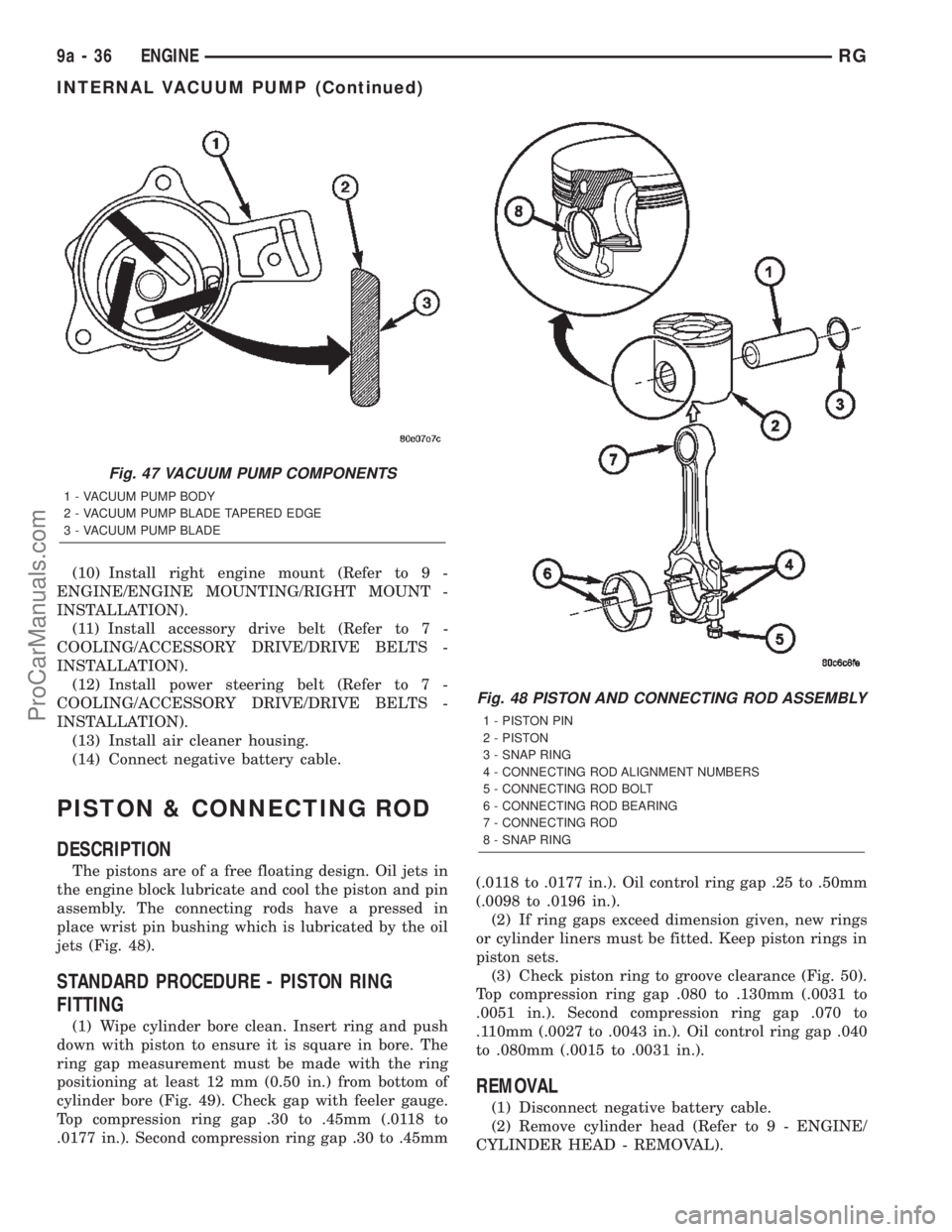
(1) Lubricate vacuum pump blades and install in
vacuum pump body as shown (Fig. 47).
(2) Install vacuum pump in engine block (Fig. 46).
Torque bolts to 10.8N´m.
(3) Install crankshaft sprocket (Fig. 46). Torque
bolts to 10.8N´m.
(4) Install front engine cover (Refer to 9 -
ENGINE/ENGINE BLOCK/ENGINE COVER -
INSTALLATION).
(5) Install front crankshaft hub. Torque bolt to
304N´m.
(6) Install timing belt inner cover (Refer to 9 -
ENGINE/VALVE TIMING/TIMING BELT / CHAIN
COVER(S) - INSTALLATION).
(7) Install timing belt (Refer to 9 - ENGINE/
VALVE TIMING/TIMING BELT/CHAIN AND
SPROCKETS - INSTALLATION) .
(8) Install timing belt outer cover (Refer to 9 -
ENGINE/VALVE TIMING/TIMING BELT / CHAIN
COVER(S) - INSTALLATION).
(9) Install vibration damper/crankshaft pulley.
Fig. 45 VACUUM PUMP
Fig. 46 OIL PUMP AND VACUUM PUMP
1 - VACUUM PUMP
2 - CRANKSHAFT SPROCKET
3 - OIL PUMP
4 - ENGINE BLOCK
5 - CRANKSHAFT
RGENGINE9a-35
ProCarManuals.com
Page 1397 of 2399
(10) Install right engine mount (Refer to 9 -
ENGINE/ENGINE MOUNTING/RIGHT MOUNT -
INSTALLATION).
(11) Install accessory drive belt (Refer to 7 -
COOLING/ACCESSORY DRIVE/DRIVE BELTS -
INSTALLATION).
(12) Install power steering belt (Refer to 7 -
COOLING/ACCESSORY DRIVE/DRIVE BELTS -
INSTALLATION).
(13) Install air cleaner housing.
(14) Connect negative battery cable.
PISTON & CONNECTING ROD
DESCRIPTION
The pistons are of a free floating design. Oil jets in
the engine block lubricate and cool the piston and pin
assembly. The connecting rods have a pressed in
place wrist pin bushing which is lubricated by the oil
jets (Fig. 48).
STANDARD PROCEDURE - PISTON RING
FITTING
(1) Wipe cylinder bore clean. Insert ring and push
down with piston to ensure it is square in bore. The
ring gap measurement must be made with the ring
positioning at least 12 mm (0.50 in.) from bottom of
cylinder bore (Fig. 49). Check gap with feeler gauge.
Top compression ring gap .30 to .45mm (.0118 to
.0177 in.). Second compression ring gap .30 to .45mm(.0118 to .0177 in.). Oil control ring gap .25 to .50mm
(.0098 to .0196 in.).
(2) If ring gaps exceed dimension given, new rings
or cylinder liners must be fitted. Keep piston rings in
piston sets.
(3) Check piston ring to groove clearance (Fig. 50).
Top compression ring gap .080 to .130mm (.0031 to
.0051 in.). Second compression ring gap .070 to
.110mm (.0027 to .0043 in.). Oil control ring gap .040
to .080mm (.0015 to .0031 in.).
REMOVAL
(1) Disconnect negative battery cable.
(2) Remove cylinder head (Refer to 9 - ENGINE/
CYLINDER HEAD - REMOVAL).
Fig. 47 VACUUM PUMP COMPONENTS
1 - VACUUM PUMP BODY
2 - VACUUM PUMP BLADE TAPERED EDGE
3 - VACUUM PUMP BLADE
Fig. 48 PISTON AND CONNECTING ROD ASSEMBLY
1 - PISTON PIN
2 - PISTON
3 - SNAP RING
4 - CONNECTING ROD ALIGNMENT NUMBERS
5 - CONNECTING ROD BOLT
6 - CONNECTING ROD BEARING
7 - CONNECTING ROD
8 - SNAP RING
9a - 36 ENGINERG
INTERNAL VACUUM PUMP (Continued)
ProCarManuals.com
Page 1402 of 2399
CRANKSHAFT OIL SEAL -
FRONT
REMOVAL
(1) Disconnect negative battery cable.
(2) Remove air cleaner housing.
(3) Support engine and remove right engine mount
(Refer to 9 - ENGINE/ENGINE MOUNTING/RIGHT
MOUNT - REMOVAL).
(4) Remove power steering belt (Refer to 7 -
COOLING/ACCESSORY DRIVE/DRIVE BELTS -
REMOVAL).
(5) Remove accessory drive belt (Refer to 7 -
COOLING/ACCESSORY DRIVE/DRIVE BELTS -
REMOVAL).
(6) Remove vibration damper/crankshaft pulley
(Refer to 9 - ENGINE/ENGINE BLOCK/VIBRATION
DAMPER - REMOVAL).
(7) Remove outer timing belt cover (Refer to 9 -
ENGINE/VALVE TIMING/TIMING BELT / CHAIN
COVER(S) - REMOVAL).
(8) Remove timing belt (Refer to 9 - ENGINE/
VALVE TIMING/TIMING BELT/CHAIN AND
SPROCKETS - REMOVAL).
(9) Remove timing belt inner cover (Refer to 9 -
ENGINE/VALVE TIMING/TIMING BELT / CHAIN
COVER(S) - REMOVAL).
NOTE: Crankshaft hub retaining bolt has LHD
thread.
(10) Remove crankshaft hub.
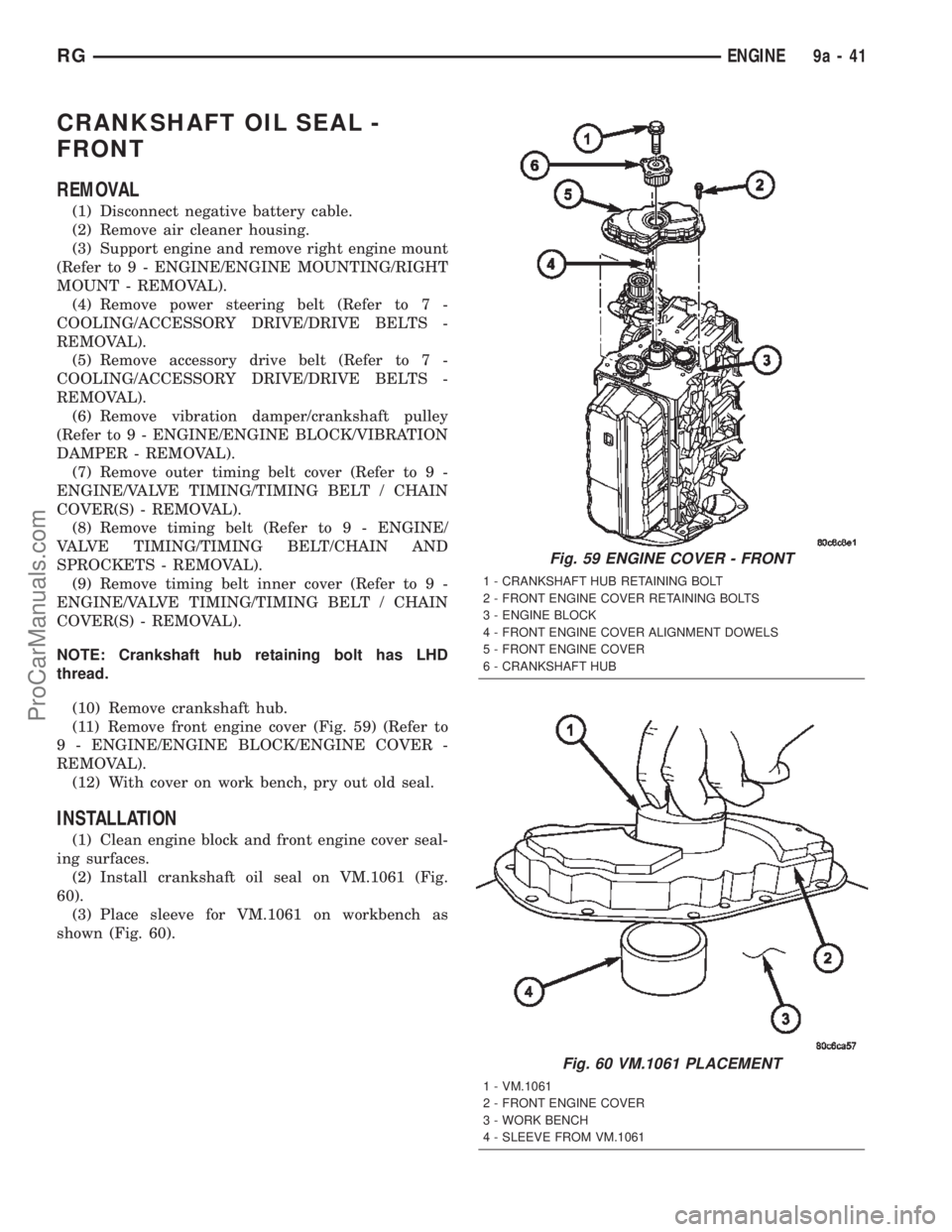
(11) Remove front engine cover (Fig. 59) (Refer to
9 - ENGINE/ENGINE BLOCK/ENGINE COVER -
REMOVAL).
(12) With cover on work bench, pry out old seal.
INSTALLATION
(1) Clean engine block and front engine cover seal-
ing surfaces.
(2) Install crankshaft oil seal on VM.1061 (Fig.
60).
(3) Place sleeve for VM.1061 on workbench as
shown (Fig. 60).
Fig. 59 ENGINE COVER - FRONT
1 - CRANKSHAFT HUB RETAINING BOLT
2 - FRONT ENGINE COVER RETAINING BOLTS
3 - ENGINE BLOCK
4 - FRONT ENGINE COVER ALIGNMENT DOWELS
5 - FRONT ENGINE COVER
6 - CRANKSHAFT HUB
Fig. 60 VM.1061 PLACEMENT
1 - VM.1061
2 - FRONT ENGINE COVER
3 - WORK BENCH
4 - SLEEVE FROM VM.1061
RGENGINE9a-41
ProCarManuals.com
Page 1403 of 2399
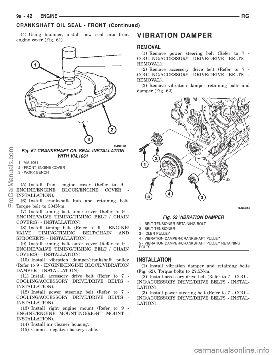
(4) Using hammer, install new seal into front
engine cover (Fig. 61).
(5) Install front engine cover (Refer to 9 -
ENGINE/ENGINE BLOCK/ENGINE COVER -
INSTALLATION).
(6) Install crankshaft hub and retaining bolt.
Torque bolt to 304N´m.
(7) Install timing belt inner cover (Refer to 9 -
ENGINE/VALVE TIMING/TIMING BELT / CHAIN
COVER(S) - INSTALLATION).
(8) Install timing belt (Refer to 9 - ENGINE/
VALVE TIMING/TIMING BELT/CHAIN AND
SPROCKETS - INSTALLATION) .
(9) Install timing belt outer cover (Refer to 9 -
ENGINE/VALVE TIMING/TIMING BELT / CHAIN
COVER(S) - INSTALLATION).
(10) Install vibration damper/crankshaft pulley
(Refer to 9 - ENGINE/ENGINE BLOCK/VIBRATION
DAMPER - INSTALLATION).
(11) Install accessory drive belt (Refer to 7 -
COOLING/ACCESSORY DRIVE/DRIVE BELTS -
INSTALLATION).
(12) Install power steering belt (Refer to 7 -
COOLING/ACCESSORY DRIVE/DRIVE BELTS -
INSTALLATION).
(13) Install right engine mount (Refer to 9 -
ENGINE/ENGINE MOUNTING/RIGHT MOUNT -
INSTALLATION).
(14) Install air cleaner housing.
(15) Connect negative battery cable.VIBRATION DAMPER
REMOVAL
(1) Remove power steering belt (Refer to 7 -
COOLING/ACCESSORY DRIVE/DRIVE BELTS -
REMOVAL).
(2) Remove accessory drive belt (Refer to 7 -
COOLING/ACCESSORY DRIVE/DRIVE BELTS -
REMOVAL).
(3) Remove vibration damper retaining bolts and
damper (Fig. 62).
INSTALLATION
(1) Install vibration damper and retaining bolts
(Fig. 62). Torque bolts to 27.5N´m.
(2) Install accessory drive belt (Refer to 7 - COOL-
ING/ACCESSORY DRIVE/DRIVE BELTS - INSTAL-
LATION).
(3) Install power steering belt (Refer to 7 - COOL-
ING/ACCESSORY DRIVE/DRIVE BELTS - INSTAL-
LATION).
Fig. 61 CRANKSHAFT OIL SEAL INSTALLATION
WITH VM.1061
1 - VM.1061
2 - FRONT ENGINE COVER
3 - WORK BENCH
Fig. 62 VIBRATION DAMPER
1 - BELT TENSIONER RETAINING BOLT
2 - BELT TENSIONER
3 - IDLER PULLEY
4 - VIBRATION DAMPER/CRANKSHAFT PULLEY
5 - VIBRATION DAMPER/CRANKSHAFT PULLEY RETAINING
BOLTS
9a - 42 ENGINERG
CRANKSHAFT OIL SEAL - FRONT (Continued)
ProCarManuals.com
Page 1404 of 2399
ENGINE COVER - FRONT
DESCRIPTION
The front engine cover on this engine is a stamped
steel cover which covers the oil pump and vacuum
pump.
REMOVAL
(1) Disconnect negative battery cable.
(2) Remove air cleaner housing.
(3) Support engine and remove right engine mount
(Refer to 9 - ENGINE/ENGINE MOUNTING/RIGHT
MOUNT - REMOVAL).
(4) Remove power steering belt (Refer to 7 -
COOLING/ACCESSORY DRIVE/DRIVE BELTS -
REMOVAL).
(5) Remove accessory drive belt (Refer to 7 -
COOLING/ACCESSORY DRIVE/DRIVE BELTS -
REMOVAL).
(6) Remove vibration damper (Refer to 9 -
ENGINE/ENGINE BLOCK/VIBRATION DAMPER -
REMOVAL).
(7) Remove timing belt outer cover (Refer to 9 -
ENGINE/VALVE TIMING/TIMING BELT / CHAIN
COVER(S) - REMOVAL).
CAUTION: Before removing the cylinder head cover/
intake manifold or timing belt the engine must put
at 90É after TDC. Failure to do so could result in
valve and/or piston damage during reassembly.
(Refer to 9 - ENGINE/VALVE TIMING - STANDARD
PROCEDURE)
(8) Remove timing belt (Refer to 9 - ENGINE/
VALVE TIMING/TIMING BELT/CHAIN AND
SPROCKETS - REMOVAL).
(9) Remove timing belt inner cover (Refer to 9 -
ENGINE/VALVE TIMING/TIMING BELT / CHAIN
COVER(S) - REMOVAL).
NOTE: Crankshaft hub has LHD thread.
(10) Remove crankshaft hub.
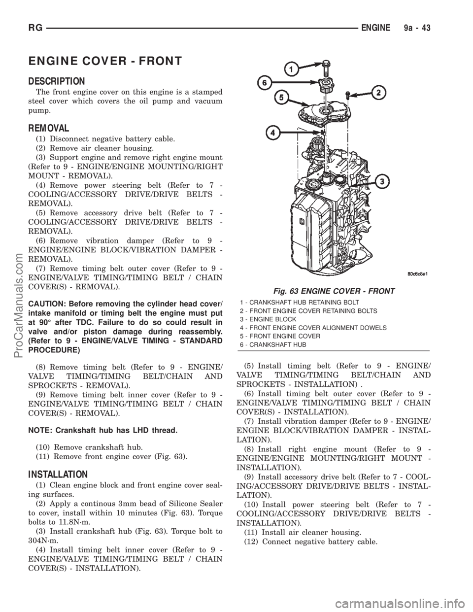
(11) Remove front engine cover (Fig. 63).
INSTALLATION
(1) Clean engine block and front engine cover seal-
ing surfaces.
(2) Apply a continous 3mm bead of Silicone Sealer
to cover, install within 10 minutes (Fig. 63). Torque
bolts to 11.8N´m.
(3) Install crankshaft hub (Fig. 63). Torque bolt to
304N´m.
(4) Install timing belt inner cover (Refer to 9 -
ENGINE/VALVE TIMING/TIMING BELT / CHAIN
COVER(S) - INSTALLATION).(5) Install timing belt (Refer to 9 - ENGINE/
VALVE TIMING/TIMING BELT/CHAIN AND
SPROCKETS - INSTALLATION) .
(6) Install timing belt outer cover (Refer to 9 -
ENGINE/VALVE TIMING/TIMING BELT / CHAIN
COVER(S) - INSTALLATION).
(7) Install vibration damper (Refer to 9 - ENGINE/
ENGINE BLOCK/VIBRATION DAMPER - INSTAL-
LATION).
(8) Install right engine mount (Refer to 9 -
ENGINE/ENGINE MOUNTING/RIGHT MOUNT -
INSTALLATION).
(9) Install accessory drive belt (Refer to 7 - COOL-
ING/ACCESSORY DRIVE/DRIVE BELTS - INSTAL-
LATION).
(10) Install power steering belt (Refer to 7 -
COOLING/ACCESSORY DRIVE/DRIVE BELTS -
INSTALLATION).
(11) Install air cleaner housing.
(12) Connect negative battery cable.
Fig. 63 ENGINE COVER - FRONT
1 - CRANKSHAFT HUB RETAINING BOLT
2 - FRONT ENGINE COVER RETAINING BOLTS
3 - ENGINE BLOCK
4 - FRONT ENGINE COVER ALIGNMENT DOWELS
5 - FRONT ENGINE COVER
6 - CRANKSHAFT HUB
RGENGINE9a-43
ProCarManuals.com