2002 CHRYSLER CARAVAN automatic transmission
[x] Cancel search: automatic transmissionPage 1849 of 2399
OPERATION
The Transmission Range Sensor (TRS) (Fig. 337)
communicates shift lever position (SLP) to the TCM
as a combination of open and closed switches. Each
shift lever position has an assigned combination of
switch states (open/closed) that the TCM receives
from four sense circuits. The TCM interprets this
information and determines the appropriate trans-
axle gear position and shift schedule.
Since there are four switches, there are 16 possible
combinations of open and closed switches (codes).
Seven of these codes are related to gear position and
three are recognized as ªbetween gearº codes. This
results in six codes which should never occur. These
are called ªinvalidº codes. An invalid code will result
in a DTC, and the TCM will then determine the shift
lever position based on pressure switch data. This
allows reasonably normal transmission operation
with a TRS failure.
TRS SWITCH STATES
SLP T42 T41 T3 T1
PCL CL CL OP
RCL OP OP OP
NCL CL OP CL
ODOP OP OP CL
3OP OP CL OP
LCL OP CL CL
TRANSMISSION TEMPERATURE SENSOR
The TRS has an integrated thermistor (Fig. 338)
that the TCM uses to monitor the transmission's
sump temperature. Since fluid temperature can
affect transmission shift quality and convertor lock
up, the TCM requires this information to determine
which shift schedule to operate in. The PCM also
monitors this temperature data so it can energize the
vehicle cooling fan(s) when a transmission ªoverheatº
condition exists. If the thermistor circuit fails, the
TCM will revert to calculated oil temperature usage.
CALCULATED TEMPERATURE
A failure in the temperature sensor or circuit will
result in calculated temperature being substituted for
actual temperature. Calculated temperature is a pre-
dicted fluid temperature which is calculated from a
combination of inputs:
²Battery (ambient) temperature
²Engine coolant temperature
²In-gear run time since start-up
REMOVAL
(1) Remove valve body assembly from transaxle.
(Refer to 21 - TRANSMISSION/TRANSAXLE/AUTO-
MATIC - 41TE/VALVE BODY - REMOVAL)
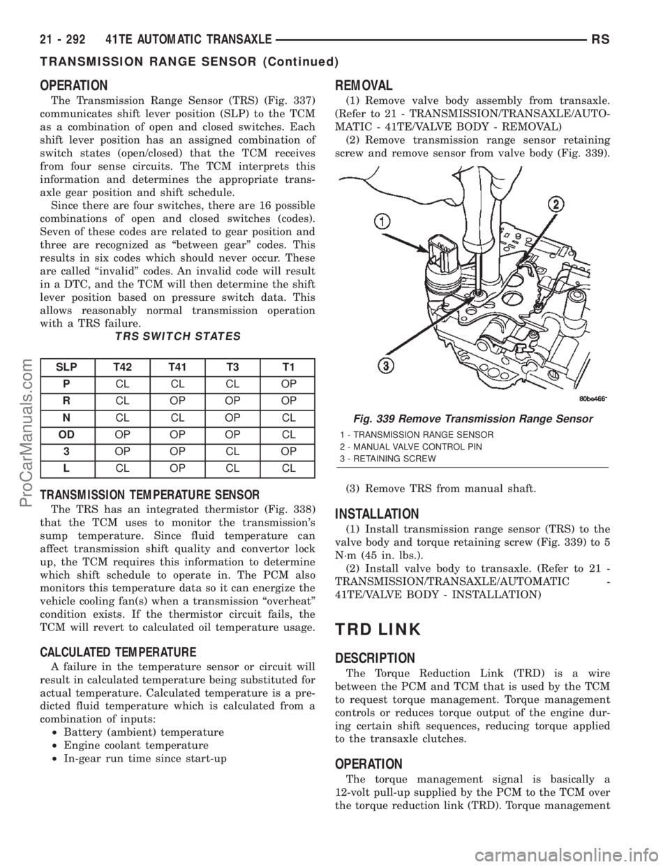
(2) Remove transmission range sensor retaining
screw and remove sensor from valve body (Fig. 339).
(3) Remove TRS from manual shaft.
INSTALLATION
(1) Install transmission range sensor (TRS) to the
valve body and torque retaining screw (Fig. 339) to 5
N´m (45 in. lbs.).
(2) Install valve body to transaxle. (Refer to 21 -
TRANSMISSION/TRANSAXLE/AUTOMATIC -
41TE/VALVE BODY - INSTALLATION)
TRD LINK
DESCRIPTION
The Torque Reduction Link (TRD) is a wire
between the PCM and TCM that is used by the TCM
to request torque management. Torque management
controls or reduces torque output of the engine dur-
ing certain shift sequences, reducing torque applied
to the transaxle clutches.
OPERATION
The torque management signal is basically a
12-volt pull-up supplied by the PCM to the TCM over
the torque reduction link (TRD). Torque management
Fig. 339 Remove Transmission Range Sensor
1 - TRANSMISSION RANGE SENSOR
2 - MANUAL VALVE CONTROL PIN
3 - RETAINING SCREW
21 - 292 41TE AUTOMATIC TRANSAXLERS
TRANSMISSION RANGE SENSOR (Continued)
ProCarManuals.com
Page 1850 of 2399
is requested when the TCM pulses this signal to
ground. The PCM recognizes this request and
responds by retarding ignition timing, killing fuel
injectors, etc. The PCM sends a confirmation of the
request to the TCM via the communication bus.
Torque reduction is not noticable by the driver, and
usually lasts for a very short period of time.
If the confirmation signal is not received by the
TCM after two sequential request messages, a diag-
nostic trouble code will be set.
VALVE BODY
DESCRIPTION
The valve body assembly consists of a cast alumi-
num valve body, a separator plate, and transfer
plate. The valve body contains valves and check balls
that control fluid delivery to the torque converter
clutch, solenoid/pressure switch assembly, and fric-
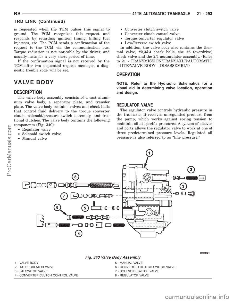
tional clutches. The valve body contains the following
components (Fig. 340):
²Regulator valve
²Solenoid switch valve
²Manual valve²Converter clutch switch valve
²Converter clutch control valve
²Torque converter regulator valve
²Low/Reverse switch valve
In addition, the valve body also contains the ther-
mal valve, #2,3&4 check balls, the #5 (overdrive)
check valve and the 2/4 accumulator assembly. (Refer
to 21 - TRANSMISSION/TRANSAXLE/AUTOMATIC
- 41TE/VALVE BODY - DISASSEMBLY)
OPERATION
NOTE: Refer to the Hydraulic Schematics for a
visual aid in determining valve location, operation
and design.
REGULATOR VALVE
The regulator valve controls hydraulic pressure in
the transaxle. It receives unregulated pressure from
the pump, which works against spring tension to
maintain oil at specific pressures. A system of sleeves
and ports allows the regulator valve to work at one of
three predetermined pressure levels. Regulated oil
pressure is also referred to as ªline pressure.º
Fig. 340 Valve Body Assembly
1 - VALVE BODY 5 - MANUAL VALVE
2 - T/C REGULATOR VALVE 6 - CONVERTER CLUTCH SWITCH VALVE
3 - L/R SWITCH VALVE 7 - SOLENOID SWITCH VALVE
4 - CONVERTER CLUTCH CONTROL VALVE 8 - REGULATOR VALVE
RS41TE AUTOMATIC TRANSAXLE21 - 293
TRD LINK (Continued)
ProCarManuals.com
Page 1851 of 2399
SOLENOID SWITCH VALVE
The solenoid switch valve controls line pressure
from the LR/CC solenoid. In one position, it allows
the low/reverse clutch to be pressurized. In the other,
it directs line pressure to the converter control and
converter clutch valves.
MANUAL VALVE
The manual valve is operated by the mechanical
shift linkage. Its primary responsibility is to send
line pressure to the appropriate hydraulic circuits
and solenoids. The valve has three operating ranges
or positions.
CONVERTER CLUTCH SWITCH VALVE
The main responsibility of the converter clutch switch
valve is to control hydraulic pressure applied to the front
(off) side of the converter clutch piston. Line pressure
from the regulator valve is fed to the torque converter
regulator valve, where it passes through the valve, and is
slightly regulated. The pressure is then directed to the
converter clutch switch valve and to the front side of the
converter clutch piston. This pressure pushes the piston
back and disengages the converter clutch.
CONVERTER CLUTCH CONTROL VALVE
The converter clutch control valve controls the
back (on) side of the torque converter clutch. When
the TCM energizes or modulates the LR/CC solenoid
to apply the converter clutch piston, both the con-
verter clutch control valve and the converter control
valve move, allowing pressure to be applied to the
back side of the clutch.
T/C REGULATOR VALVE
The torque converter regulator valve slightly regu-
lates the flow of fluid to the torque converter.
LOW/REVERSE SWITCH VALVE
The low/reverse clutch is applied from different
sources, depending on whether low (1st) gear or
reverse is selected. The low/reverse switch valve
alternates positions depending on from which direc-
tion fluid pressure is applied. By design, when the
valve is shifted by fluid pressure from one channel,
the opposing channel is blocked. The switch valve
alienates the possibility of a sticking ball check, thus
providing consistent application of the low/reverse
clutch under all operating conditions.
REMOVAL
REMOVAL
NOTE: If valve body is replaced or reconditioned,
the TCM Quick Learn Procedure must be per-formed. (Refer to 8 - ELECTRICAL/ELECTRONIC
CONTROL MODULES/TRANSMISSION CONTROL
MODULE - STANDARD PROCEDURE)
(1) Disconnect battery negative cable.
(2) Disconnect gearshift cable from manual valve
lever.
(3) Remove manual valve lever from manual shaft.
(4) Raise vehicle on hoist.
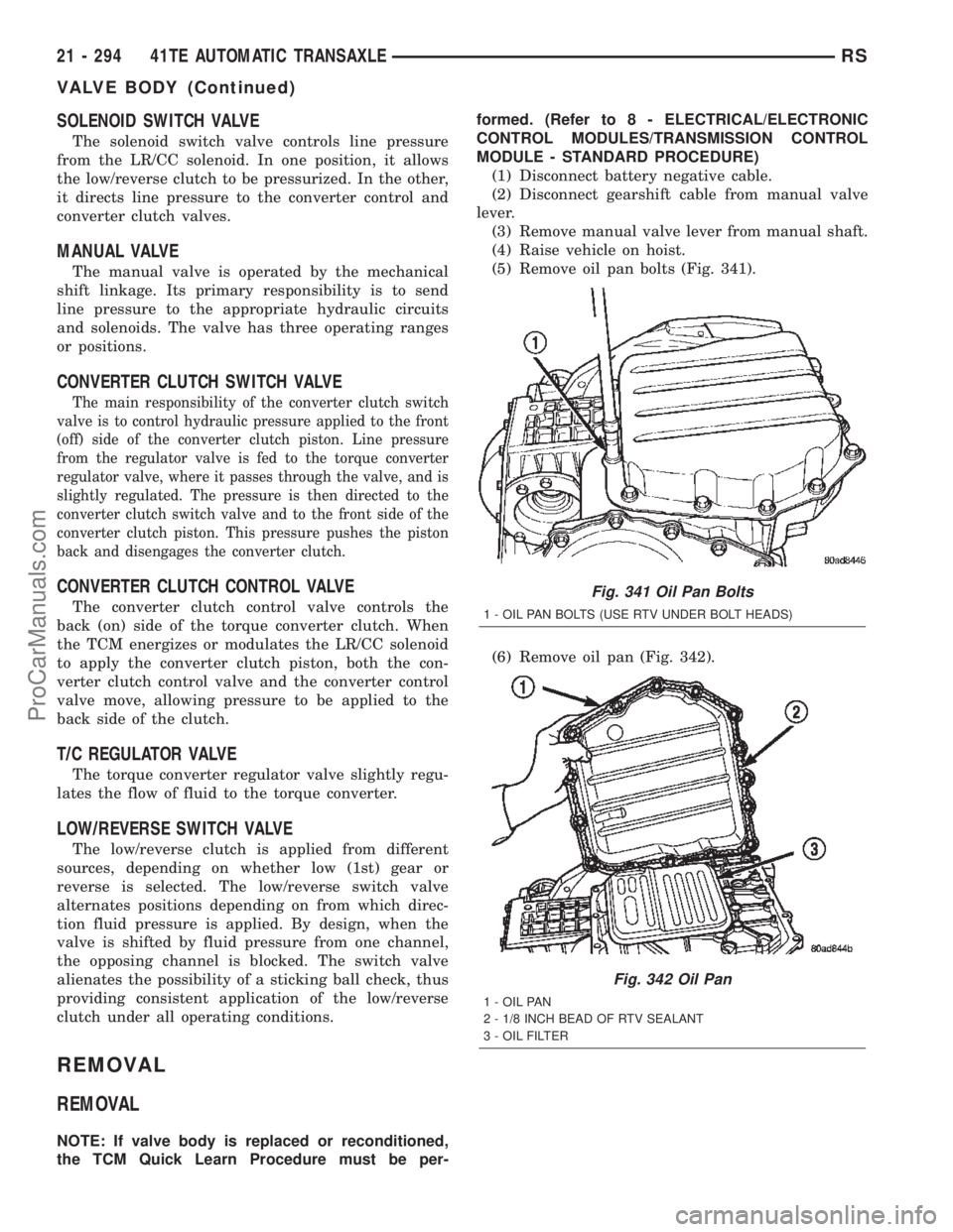
(5) Remove oil pan bolts (Fig. 341).
(6) Remove oil pan (Fig. 342).
Fig. 341 Oil Pan Bolts
1 - OIL PAN BOLTS (USE RTV UNDER BOLT HEADS)
Fig. 342 Oil Pan
1 - OIL PAN
2 - 1/8 INCH BEAD OF RTV SEALANT
3 - OIL FILTER
21 - 294 41TE AUTOMATIC TRANSAXLERS
VALVE BODY (Continued)
ProCarManuals.com
Page 1853 of 2399
REMOVAL
NOTE: If valve body is replaced or reconditioned,
the TCM Quick Learn Procedure must be per-
formed. (Refer to 8 - ELECTRICAL/ELECTRONIC
CONTROL MODULES/TRANSMISSION CONTROL
MODULE - STANDARD PROCEDURE)
(1) Disconnect battery negative cable.
(2) Disconnect gearshift cable from manual valve
lever.
(3) Remove manual valve lever from manual shaft.
(4) Raise vehicle on hoist.
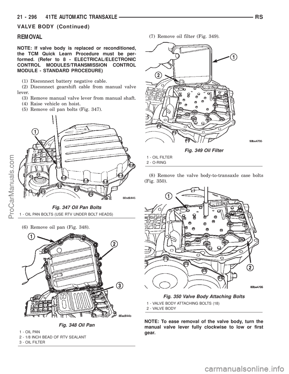
(5) Remove oil pan bolts (Fig. 347).
(6) Remove oil pan (Fig. 348).(7) Remove oil filter (Fig. 349).
(8) Remove the valve body-to-transaxle case bolts
(Fig. 350).
NOTE: To ease removal of the valve body, turn the
manual valve lever fully clockwise to low or first
gear.
Fig. 347 Oil Pan Bolts
1 - OIL PAN BOLTS (USE RTV UNDER BOLT HEADS)
Fig. 348 Oil Pan
1 - OIL PAN
2 - 1/8 INCH BEAD OF RTV SEALANT
3 - OIL FILTER
Fig. 349 Oil Filter
1 - OIL FILTER
2 - O-RING
Fig. 350 Valve Body Attaching Bolts
1 - VALVE BODY ATTACHING BOLTS (18)
2 - VALVE BODY
21 - 296 41TE AUTOMATIC TRANSAXLERS
VALVE BODY (Continued)
ProCarManuals.com
Page 1854 of 2399

(9) Remove park rod rollers from guide bracket
and remove valve body from transaxle (Fig. 351) (Fig.
352).
CAUTION: The valve body manual shaft pilot may
distort and bind the manual valve if the valve body
is mishandled or dropped.
DISASSEMBLY
NOTE: If valve body assembly is being recondi-
tioned, the TCM Quick Learn Procedure must be
performed. (Refer to 8 - ELECTRICAL/ELECTRONIC
CONTROL MODULES/TRANSMISSION CONTROL
MODULE - STANDARD PROCEDURE)(1) Remove manual shaft seal (Fig. 353).
(2) Remove Transmission Range Sensor retaining
screw (Fig. 354).
Fig. 351 Push Park Rod Rollers from Guide Bracket
1 - PARK SPRAG ROLLERS
2 - SCREWDRIVER
3 - PARK SPRAG GUIDE BRACKET
Fig. 352 Valve Body Removal/Installation
1 - VALVE BODY
Fig. 353 Manual Shaft Seal
1 - SEAL
2 - MANUAL SHAFT
Fig. 354 Remove Transmission Range Sensor
1 - TRANSMISSION RANGE SENSOR
2 - MANUAL VALVE CONTROL PIN
3 - RETAINING SCREW
RS41TE AUTOMATIC TRANSAXLE21 - 297
VALVE BODY (Continued)
ProCarManuals.com
Page 1855 of 2399
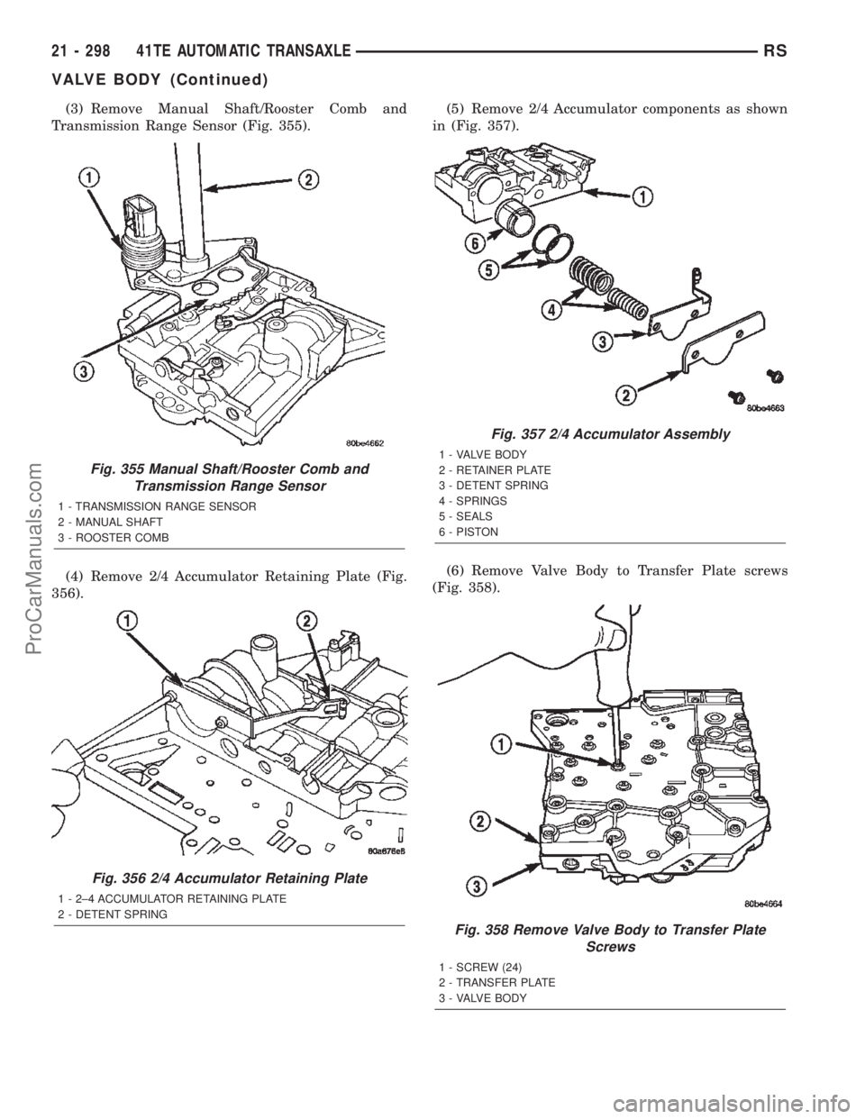
(3) Remove Manual Shaft/Rooster Comb and
Transmission Range Sensor (Fig. 355).
(4) Remove 2/4 Accumulator Retaining Plate (Fig.
356).(5) Remove 2/4 Accumulator components as shown
in (Fig. 357).
(6) Remove Valve Body to Transfer Plate screws
(Fig. 358).
Fig. 355 Manual Shaft/Rooster Comb and
Transmission Range Sensor
1 - TRANSMISSION RANGE SENSOR
2 - MANUAL SHAFT
3 - ROOSTER COMB
Fig. 356 2/4 Accumulator Retaining Plate
1 - 2±4 ACCUMULATOR RETAINING PLATE
2 - DETENT SPRING
Fig. 357 2/4 Accumulator Assembly
1 - VALVE BODY
2 - RETAINER PLATE
3 - DETENT SPRING
4 - SPRINGS
5 - SEALS
6 - PISTON
Fig. 358 Remove Valve Body to Transfer Plate
Screws
1 - SCREW (24)
2 - TRANSFER PLATE
3 - VALVE BODY
21 - 298 41TE AUTOMATIC TRANSAXLERS
VALVE BODY (Continued)
ProCarManuals.com
Page 1858 of 2399
NOTE: Tag all valve/spring assemblies for reassem-
bly identification.
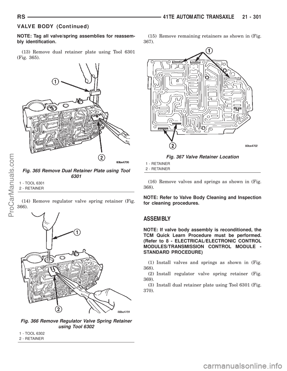
(13) Remove dual retainer plate using Tool 6301
(Fig. 365).
(14) Remove regulator valve spring retainer (Fig.
366).(15) Remove remaining retainers as shown in (Fig.
367).
(16) Remove valves and springs as shown in (Fig.
368).
NOTE: Refer to Valve Body Cleaning and Inspection
for cleaning procedures.
ASSEMBLY
NOTE: If valve body assembly is reconditioned, the
TCM Quick Learn Procedure must be performed.
(Refer to 8 - ELECTRICAL/ELECTRONIC CONTROL
MODULES/TRANSMISSION CONTROL MODULE -
STANDARD PROCEDURE)
(1) Install valves and springs as shown in (Fig.
368).
(2) Install regulator valve spring retainer (Fig.
369).
(3) Install dual retainer plate using Tool 6301 (Fig.
370).
Fig. 365 Remove Dual Retainer Plate using Tool
6301
1 - TOOL 6301
2 - RETAINER
Fig. 366 Remove Regulator Valve Spring Retainer
using Tool 6302
1 - TOOL 6302
2 - RETAINER
Fig. 367 Valve Retainer Location
1 - RETAINER
2 - RETAINER
RS41TE AUTOMATIC TRANSAXLE21 - 301
VALVE BODY (Continued)
ProCarManuals.com
Page 1860 of 2399
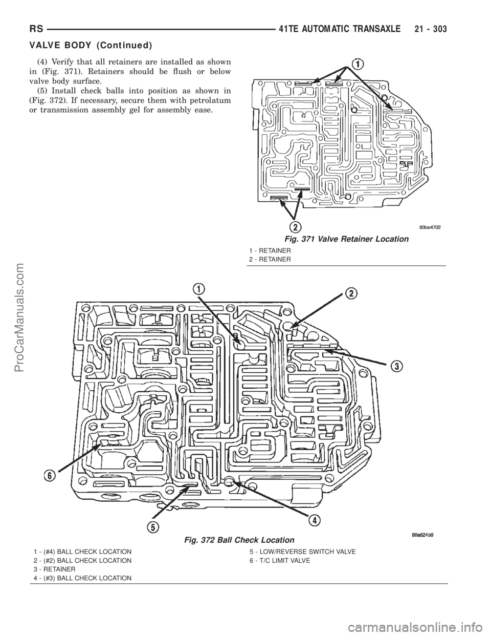
(4) Verify that all retainers are installed as shown
in (Fig. 371). Retainers should be flush or below
valve body surface.
(5) Install check balls into position as shown in
(Fig. 372). If necessary, secure them with petrolatum
or transmission assembly gel for assembly ease.
Fig. 372 Ball Check Location
1 - (#4) BALL CHECK LOCATION
2 - (#2) BALL CHECK LOCATION
3 - RETAINER
4 - (#3) BALL CHECK LOCATION5 - LOW/REVERSE SWITCH VALVE
6 - T/C LIMIT VALVE
Fig. 371 Valve Retainer Location
1 - RETAINER
2 - RETAINER
RS41TE AUTOMATIC TRANSAXLE21 - 303
VALVE BODY (Continued)
ProCarManuals.com