2002 CHRYSLER CARAVAN tow
[x] Cancel search: towPage 1300 of 2399
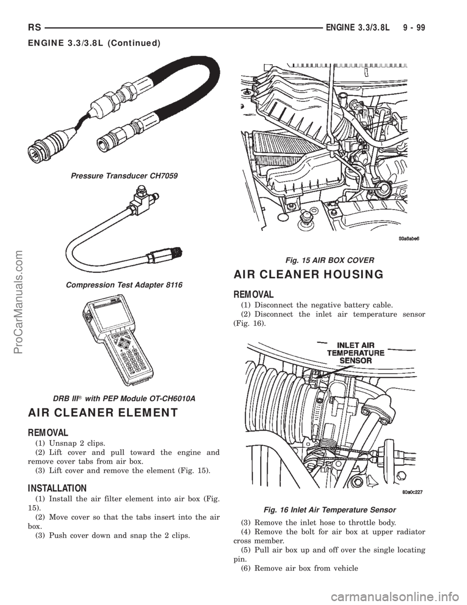
AIR CLEANER ELEMENT
REMOVAL
(1) Unsnap 2 clips.
(2) Lift cover and pull toward the engine and
remove cover tabs from air box.
(3) Lift cover and remove the element (Fig. 15).
INSTALLATION
(1) Install the air filter element into air box (Fig.
15).
(2) Move cover so that the tabs insert into the air
box.
(3) Push cover down and snap the 2 clips.
AIR CLEANER HOUSING
REMOVAL
(1) Disconnect the negative battery cable.
(2) Disconnect the inlet air temperature sensor
(Fig. 16).
(3) Remove the inlet hose to throttle body.
(4) Remove the bolt for air box at upper radiator
cross member.
(5) Pull air box up and off over the single locating
pin.
(6) Remove air box from vehicle
Pressure Transducer CH7059
Compression Test Adapter 8116
DRB IIITwith PEP Module OT-CH6010A
Fig. 15 AIR BOX COVER
Fig. 16 Inlet Air Temperature Sensor
RSENGINE 3.3/3.8L9-99
ENGINE 3.3/3.8L (Continued)
ProCarManuals.com
Page 1313 of 2399
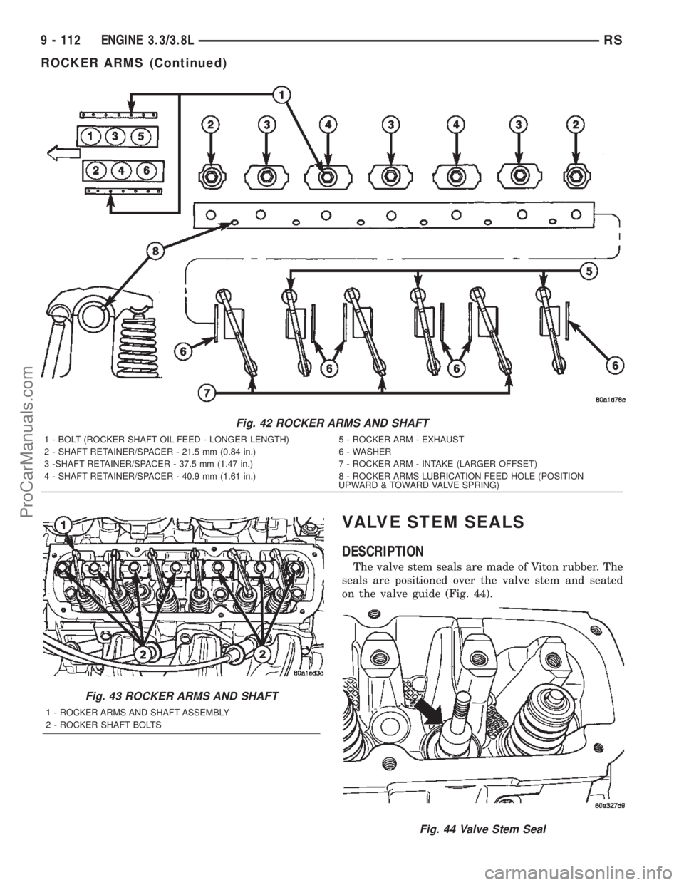
VALVE STEM SEALS
DESCRIPTION
The valve stem seals are made of Viton rubber. The
seals are positioned over the valve stem and seated
on the valve guide (Fig. 44).
Fig. 42 ROCKER ARMS AND SHAFT
1 - BOLT (ROCKER SHAFT OIL FEED - LONGER LENGTH) 5 - ROCKER ARM - EXHAUST
2 - SHAFT RETAINER/SPACER - 21.5 mm (0.84 in.) 6 - WASHER
3 -SHAFT RETAINER/SPACER - 37.5 mm (1.47 in.) 7 - ROCKER ARM - INTAKE (LARGER OFFSET)
4 - SHAFT RETAINER/SPACER - 40.9 mm (1.61 in.) 8 - ROCKER ARMS LUBRICATION FEED HOLE (POSITION
UPWARD & TOWARD VALVE SPRING)
Fig. 43 ROCKER ARMS AND SHAFT
1 - ROCKER ARMS AND SHAFT ASSEMBLY
2 - ROCKER SHAFT BOLTS
Fig. 44 Valve Stem Seal
9 - 112 ENGINE 3.3/3.8LRS
ROCKER ARMS (Continued)
ProCarManuals.com
Page 1327 of 2399
the plunger and the lifter body causing the plunger
to stick in the down position. This heavy click will be
accompanied by excessive clearance between the
valve stem and rocker arm as valve closes. In either
case, lifter assembly should be removed for inspec-
tion.
REMOVAL
(1) Remove the cylinder head(s). (Refer to 9 -
ENGINE/CYLINDER HEAD - REMOVAL)
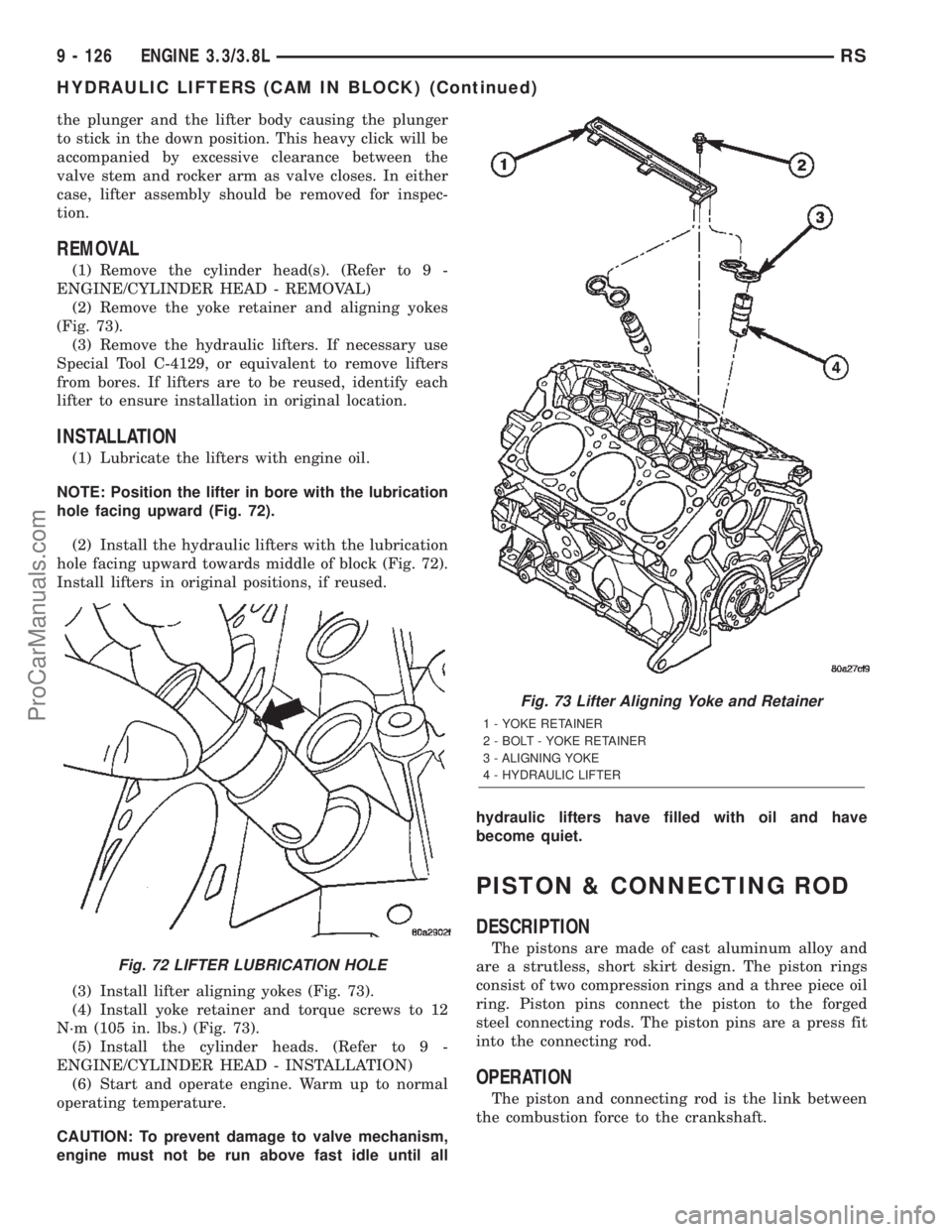
(2) Remove the yoke retainer and aligning yokes
(Fig. 73).
(3) Remove the hydraulic lifters. If necessary use
Special Tool C-4129, or equivalent to remove lifters
from bores. If lifters are to be reused, identify each
lifter to ensure installation in original location.
INSTALLATION
(1) Lubricate the lifters with engine oil.
NOTE: Position the lifter in bore with the lubrication
hole facing upward (Fig. 72).
(2) Install the hydraulic lifters with the lubrication
hole facing upward towards middle of block (Fig. 72).
Install lifters in original positions, if reused.
(3) Install lifter aligning yokes (Fig. 73).
(4) Install yoke retainer and torque screws to 12
N´m (105 in. lbs.) (Fig. 73).
(5) Install the cylinder heads. (Refer to 9 -
ENGINE/CYLINDER HEAD - INSTALLATION)
(6) Start and operate engine. Warm up to normal
operating temperature.
CAUTION: To prevent damage to valve mechanism,
engine must not be run above fast idle until allhydraulic lifters have filled with oil and have
become quiet.
PISTON & CONNECTING ROD
DESCRIPTION
The pistons are made of cast aluminum alloy and
are a strutless, short skirt design. The piston rings
consist of two compression rings and a three piece oil
ring. Piston pins connect the piston to the forged
steel connecting rods. The piston pins are a press fit
into the connecting rod.
OPERATION
The piston and connecting rod is the link between
the combustion force to the crankshaft.
Fig. 72 LIFTER LUBRICATION HOLE
Fig. 73 Lifter Aligning Yoke and Retainer
1 - YOKE RETAINER
2 - BOLT - YOKE RETAINER
3 - ALIGNING YOKE
4 - HYDRAULIC LIFTER
9 - 126 ENGINE 3.3/3.8LRS
HYDRAULIC LIFTERS (CAM IN BLOCK) (Continued)
ProCarManuals.com
Page 1339 of 2399

OIL
STANDARD PROCEDURE
STANDARD PROCEDURE - ENGINE OIL AND
FILTER CHANGE
Change engine oil at mileage and time intervals
described in the Maintenance Schedule. (Refer to
LUBRICATION & MAINTENANCE/MAINTE-
NANCE SCHEDULES - DESCRIPTION)
WARNING: NEW OR USED ENGINE OIL CAN BE
IRRITATING TO THE SKIN. AVOID PROLONGED OR
REPEATED SKIN CONTACT WITH ENGINE OIL.
CONTAMINANTS IN USED ENGINE OIL, CAUSED BY
INTERNAL COMBUSTION, CAN BE HAZARDOUS TO
YOUR HEALTH. THOROUGHLY WASH EXPOSED
SKIN WITH SOAP AND WATER. DO NOT WASH
SKIN WITH GASOLINE, DIESEL FUEL, THINNER, OR
SOLVENTS, HEALTH PROBLEMS CAN RESULT. DO
NOT POLLUTE, DISPOSE OF USED ENGINE OIL
PROPERLY. CONTACT YOUR DEALER OR GOVERN-MENT AGENCY FOR LOCATION OF COLLECTION
CENTER IN YOUR AREA.
Run engine until achieving normal operating tem-
perature.
(1) Position the vehicle on a level surface and turn
engine off.
(2) Open hood, remove oil fill cap.
(3) Hoist and support vehicle on safety stands.
Refer to Hoisting and Jacking Recommendations.
(Refer to LUBRICATION & MAINTENANCE/HOIST-
ING - STANDARD PROCEDURE)
(4) Place a suitable drain pan under crankcase
drain (Fig. 101).
(5) Remove drain plug from crankcase (Fig. 101)
and allow oil to drain into pan. Inspect drain plug
threads for stretching or other damage. Replace
drain plug and gasket if damaged.
(6) Remove oil filter. (Refer to 9 - ENGINE/LUBRI-
CATION/OIL FILTER - REMOVAL)
(7) Install and tighten drain plug in crankcase.
(8) Install new oil filter. (Refer to 9 - ENGINE/LU-
BRICATION/OIL FILTER - INSTALLATION)
Fig. 100 Engine Oiling System
1 - OIL SUPPLY FOR BALL SOCKET THROUGH PUSH ROD 7 - OUTER ROTOR
2 - OIL SUPPLY PASSAGE FROM SHAFT TO ROCKER ARM 8 - INNER ROTOR
3 - ROCKER SHAFT 9 - RELIEF VALVE
4 - OIL FLOWS TO ONLY ONE PEDASTAL ON EACH HEAD; THIRD
FROM REAR ON RIGHT HEAD, THIRD FROM FRONT ON LEFT
HEAD10 - OIL PAN
5 - ROCKER SHAFT TOWER 11 - OIL SCREEN
6 - CRANKSHAFT 12 - OIL PUMP CASE
9 - 138 ENGINE 3.3/3.8LRS
LUBRICATION (Continued)
ProCarManuals.com
Page 1393 of 2399

(11) Remove rear main bearing support by thread-
ing two retaining bolts in holes provided. Tighten
bolts equally to push main bearing support out of
block (Fig. 37).
(12) Remove front engine cover (Refer to 9 -
ENGINE/ENGINE BLOCK/ENGINE COVER -
REMOVAL).
(13) Remove crankshaft sprocket.
(14) Remove oil pan (Refer to 9 - ENGINE/LUBRI-
CATION/OIL PAN - REMOVAL).
(15) Remove oil pump pickup tube (Refer to 9 -
ENGINE/LUBRICATION/OIL PUMP - REMOVAL).
(16) Remove balance shaft assembly (Refer to 9 -
ENGINE/VALVE TIMING/BALANCE SHAFT -
REMOVAL).
(17) Remove oil jets (Refer to 9 - ENGINE/LUBRI-
CATION/OIL JET - REMOVAL).
(18) Remove piston and connecting rod assemblies
(Refer to 9 - ENGINE/ENGINE BLOCK/PISTON &
CONNECTING ROD - REMOVAL).
(19) Slide special tool VM.1069 on crankshaft (Fig.
38).
(20) Using special tool VM.1054, remove crank-
shaft support retainers (Fig. 39).
(21) Slide crankshaft out rear of engine block.
INSTALLATION
NOTE: Before installing crankshaft in engine block,
be sure the notches in the crankshaft supports are
facing towards the front of the engine.(1) Install crankshaft in engine block.Be sure to
align oil holes in crankshaft supports and
engine block.
(2) Install crankshaft support retainers (Fig. 39).
(3) Remove special tool VM.1069 from crankshaft
(Fig. 38).
(4) Install crankshaft sprocket.
Fig. 37 REAR MAIN BEARING SUPPORT REMOVAL
1 - BOLTS
2 - REAR MAIN BEARING SUPPORT
3 - CRANKSHAFT
Fig. 38 CRANKSHAFT SLEEVE VM.1069
1 - CRANKSHAFT SLEEVE VM.1069
2 - ENGINE BLOCK
Fig. 39 CRANKSHAFT SUPPORT RETAINERS/
BALANCE SHAFT OIL FEED
1 - CRANKSHAFT SUPPORT RETAINERS/BALANCE SHAFT OIL
FEED
2 - ENGINE BLOCK
9a - 32 ENGINERG
CRANKSHAFT (Continued)
ProCarManuals.com
Page 1399 of 2399
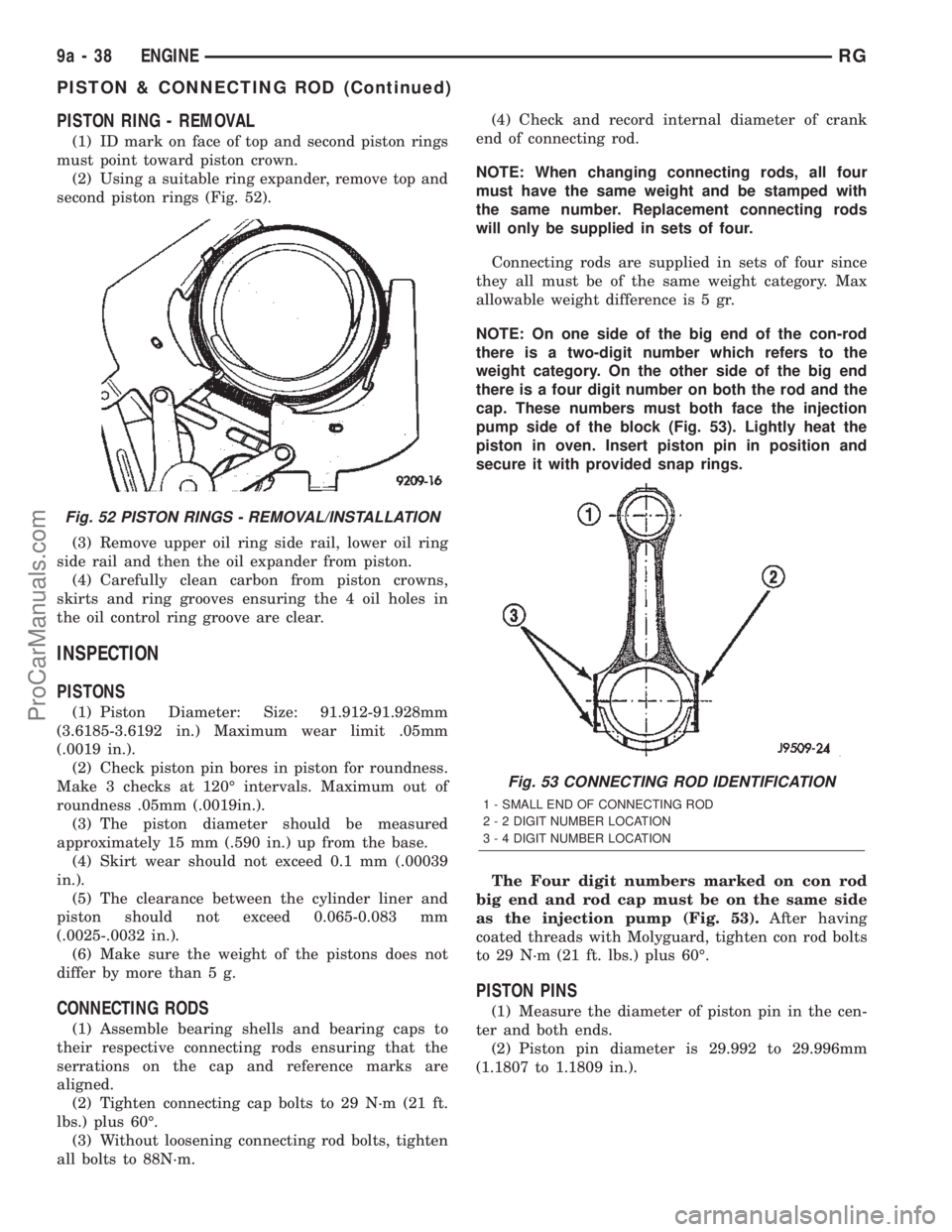
PISTON RING - REMOVAL
(1) ID mark on face of top and second piston rings
must point toward piston crown.
(2) Using a suitable ring expander, remove top and
second piston rings (Fig. 52).
(3) Remove upper oil ring side rail, lower oil ring
side rail and then the oil expander from piston.
(4) Carefully clean carbon from piston crowns,
skirts and ring grooves ensuring the 4 oil holes in
the oil control ring groove are clear.
INSPECTION
PISTONS
(1) Piston Diameter: Size: 91.912-91.928mm
(3.6185-3.6192 in.) Maximum wear limit .05mm
(.0019 in.).
(2) Check piston pin bores in piston for roundness.
Make 3 checks at 120É intervals. Maximum out of
roundness .05mm (.0019in.).
(3) The piston diameter should be measured
approximately 15 mm (.590 in.) up from the base.
(4) Skirt wear should not exceed 0.1 mm (.00039
in.).
(5) The clearance between the cylinder liner and
piston should not exceed 0.065-0.083 mm
(.0025-.0032 in.).
(6) Make sure the weight of the pistons does not
differ by more than 5 g.
CONNECTING RODS
(1) Assemble bearing shells and bearing caps to
their respective connecting rods ensuring that the
serrations on the cap and reference marks are
aligned.
(2) Tighten connecting cap bolts to 29 N´m (21 ft.
lbs.) plus 60É.
(3) Without loosening connecting rod bolts, tighten
all bolts to 88N´m.(4) Check and record internal diameter of crank
end of connecting rod.
NOTE: When changing connecting rods, all four
must have the same weight and be stamped with
the same number. Replacement connecting rods
will only be supplied in sets of four.
Connecting rods are supplied in sets of four since
they all must be of the same weight category. Max
allowable weight difference is 5 gr.
NOTE: On one side of the big end of the con-rod
there is a two-digit number which refers to the
weight category. On the other side of the big end
there is a four digit number on both the rod and the
cap. These numbers must both face the injection
pump side of the block (Fig. 53). Lightly heat the
piston in oven. Insert piston pin in position and
secure it with provided snap rings.
The Four digit numbers marked on con rod
big end and rod cap must be on the same side
as the injection pump (Fig. 53).After having
coated threads with Molyguard, tighten con rod bolts
to 29 N´m (21 ft. lbs.) plus 60É.
PISTON PINS
(1) Measure the diameter of piston pin in the cen-
ter and both ends.
(2) Piston pin diameter is 29.992 to 29.996mm
(1.1807 to 1.1809 in.).
Fig. 52 PISTON RINGS - REMOVAL/INSTALLATION
Fig. 53 CONNECTING ROD IDENTIFICATION
1 - SMALL END OF CONNECTING ROD
2 - 2 DIGIT NUMBER LOCATION
3 - 4 DIGIT NUMBER LOCATION
9a - 38 ENGINERG
PISTON & CONNECTING ROD (Continued)
ProCarManuals.com
Page 1401 of 2399
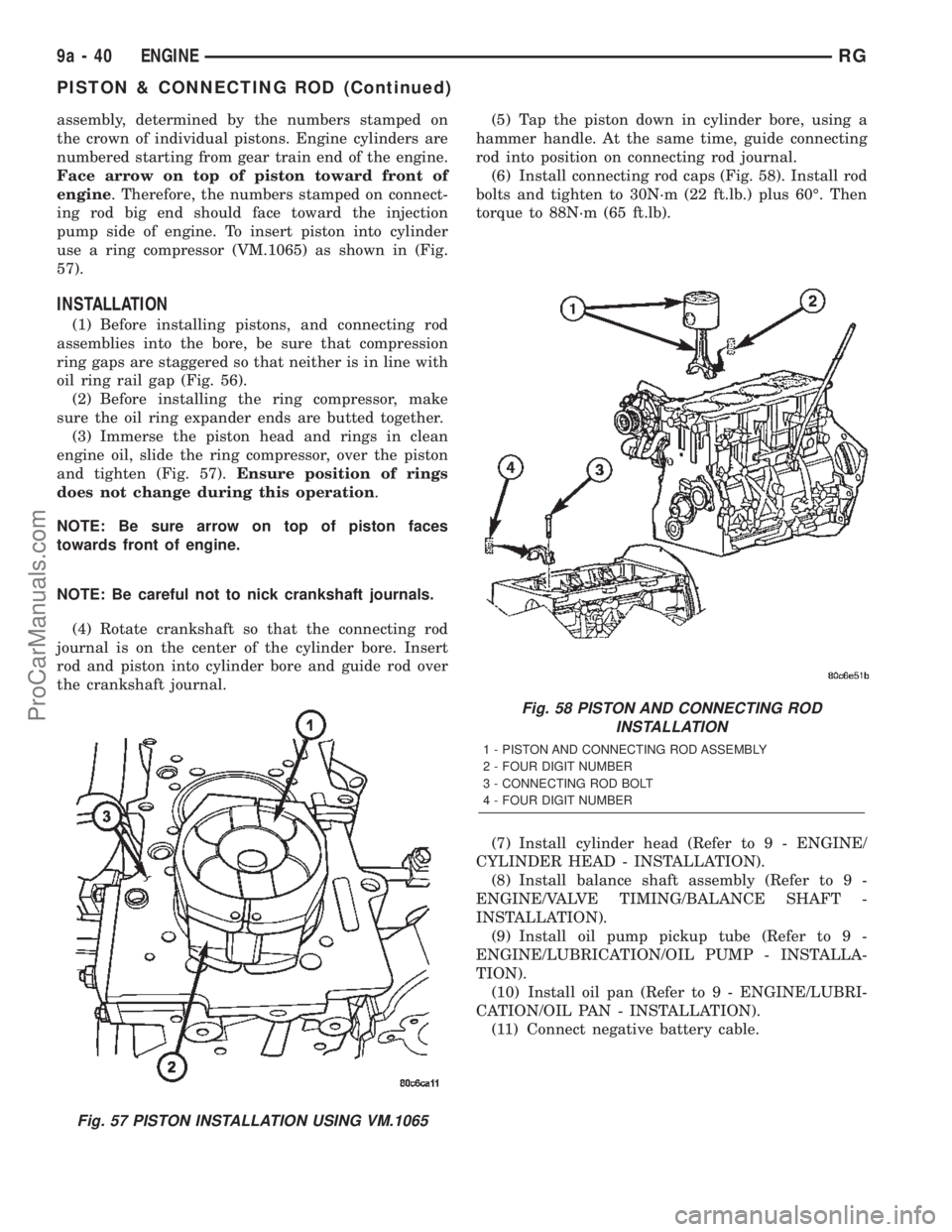
assembly, determined by the numbers stamped on
the crown of individual pistons. Engine cylinders are
numbered starting from gear train end of the engine.
Face arrow on top of piston toward front of
engine. Therefore, the numbers stamped on connect-
ing rod big end should face toward the injection
pump side of engine. To insert piston into cylinder
use a ring compressor (VM.1065) as shown in (Fig.
57).
INSTALLATION
(1) Before installing pistons, and connecting rod
assemblies into the bore, be sure that compression
ring gaps are staggered so that neither is in line with
oil ring rail gap (Fig. 56).
(2) Before installing the ring compressor, make
sure the oil ring expander ends are butted together.
(3) Immerse the piston head and rings in clean
engine oil, slide the ring compressor, over the piston
and tighten (Fig. 57).Ensure position of rings
does not change during this operation.
NOTE: Be sure arrow on top of piston faces
towards front of engine.
NOTE: Be careful not to nick crankshaft journals.
(4) Rotate crankshaft so that the connecting rod
journal is on the center of the cylinder bore. Insert
rod and piston into cylinder bore and guide rod over
the crankshaft journal.(5) Tap the piston down in cylinder bore, using a
hammer handle. At the same time, guide connecting
rod into position on connecting rod journal.
(6) Install connecting rod caps (Fig. 58). Install rod
bolts and tighten to 30N´m (22 ft.lb.) plus 60É. Then
torque to 88N´m (65 ft.lb).
(7) Install cylinder head (Refer to 9 - ENGINE/
CYLINDER HEAD - INSTALLATION).
(8) Install balance shaft assembly (Refer to 9 -
ENGINE/VALVE TIMING/BALANCE SHAFT -
INSTALLATION).
(9) Install oil pump pickup tube (Refer to 9 -
ENGINE/LUBRICATION/OIL PUMP - INSTALLA-
TION).
(10) Install oil pan (Refer to 9 - ENGINE/LUBRI-
CATION/OIL PAN - INSTALLATION).
(11) Connect negative battery cable.
Fig. 57 PISTON INSTALLATION USING VM.1065
Fig. 58 PISTON AND CONNECTING ROD
INSTALLATION
1 - PISTON AND CONNECTING ROD ASSEMBLY
2 - FOUR DIGIT NUMBER
3 - CONNECTING ROD BOLT
4 - FOUR DIGIT NUMBER
9a - 40 ENGINERG
PISTON & CONNECTING ROD (Continued)
ProCarManuals.com
Page 1460 of 2399

WARNING: THE FUEL RESERVOIR OF THE FUEL
PUMP MODULE DOES NOT EMPTY OUT WHEN THE
TANK IS DRAINED. THE FUEL IN THE RESERVOIR
MAY SPILL OUT WHEN THE MODULE IS REMOVED.
(7) Remove fuel pump module and O-ring from
tank (Fig. 12). Discard O-ring.
INSTALLATION
(1) Wipe seal area of tank clean and place a new
O-ring seal in position on pump.
(2) Position fuel pump module in tank.
(3) Tighten locknut using a brass punch and ham-
mer to install the locknut (Fig. 11).
(4) Install fuel tank, refer to the Fuel Tank instal-
lation section.
(5) Lower vehicle.
(6) Connect negative cable battery.
(7) Fill fuel tank. Check for leaks.
(8) Install fuel filler cap.
FUEL RAIL
REMOVAL
REMOVAL - 2.4L
(1) Perform fuel system pressure release procedure
before servicing or starting repairs.Refer to
Fuel System Pressure Release Procedure in this sec-
tion.
(2) Disconnect negative cable from battery.
(3) Disconnect the wiring connectors for fuel injec-
tors harness (Fig. 13).
(4) Remove wiring harness from brackets.(5) Disconnect the connectors from the fuel injec-
tors.
(6) Remove harness from vehicle.
(7) Remove fuel hose quick connect fitting from the
chassis tube.Refer to Fuel Hoses, Clamps and
Quick Connect Fittings in this Section.Place a
shop towel under the connections to absorb any fuel
spilled from the fitting.
WARNING: WRAP A SHOP TOWEL AROUND HOSES
TO CATCH ANY GASOLINE SPILLAGE.
(8) Remove fuel rail attaching bolts.
(9) Remove fuel rail. Be careful not to damage the
injector O-rings upon removal from their ports.
REMOVAL - 3.3/3.8L
(1) Perform fuel system pressure release procedure
before servicing or starting repairs.Refer to
Fuel System Pressure Release Procedure in this sec-
tion.
(2) Disconnect negative cable from battery.
(3) Remove upper intake manifold, refer to the
Engine/Manifolds/Upper Intake for more informa-
tion..
(4) Cover intake manifold with suitable cover
when servicing.
(5) Remove the fuel hose quick connect fitting from
the chassis tube.Refer to Fuel Hoses, Clamps
and Quick Connect Fittings in this Section.
WARNING: WRAP A SHOP TOWEL AROUND HOSES
TO CATCH ANY GASOLINE SPILLAGE.
(6) Remove the fuel rail attaching bolts (Fig. 14).
(7) Remove fuel rail. Be careful not to damage the
injector O-rings upon removal from their ports.
Fig. 12 Fuel Pump Module Removal
1 - FUEL PUMP MODULE
2 - O-RING
Fig. 13 FUEL RAIL AND INJECTORS 2.4L
1 - Fuel Injectors
2 - Fuel Rail
RSFUEL DELIVERY14-9
FUEL PUMP MODULE (Continued)
ProCarManuals.com