2002 CHRYSLER CARAVAN oil pressure
[x] Cancel search: oil pressurePage 1288 of 2399
REMOVAL - ENGINE ASSEMBLY
(1) Perform fuel pressure release procedure (Refer
to 14 - FUEL SYSTEM/FUEL DELIVERY - STAN-
DARD PROCEDURE).
(2) Disconnect negative battery cable.
(3) Remove air cleaner and hoses.
(4) Disconnect the fuel line from fuel rail (Refer to
14 - FUEL SYSTEM/FUEL DELIVERY/QUICK
CONNECT FITTING - STANDARD PROCEDURE).
(5) Remove the wiper module (Refer to 8 - ELEC-
TRICAL/WIPERS/WASHERS/WIPER MODULE -
REMOVAL).
(6) Block off heater hoses to the rear heater sys-
tem using pinch-off pliers (if equipped).
(7) Drain the cooling system (Refer to 7 - COOL-
ING - STANDARD PROCEDURE).
(8) Disconnect the heater hoses.
(9) Remove the radiator upper support crossmem-
ber (Refer to 23 - BODY/EXTERIOR/GRILLE OPEN-
ING REINFORCEMENT - REMOVAL).
(10) Remove the radiator fans (Refer to 7 - COOL-
ING/ENGINE/RADIATOR FAN - REMOVAL).
(11) Disconnect the throttle cables from the throt-
tle body.
(12) Disconnect the MAP, IAC, and TPS electrical
connectors.
(13) Disconnect the EGR transducer electrical con-
nector (if equipped).
(14) Disconnect the vacuum hoses from throttle
body.
(15) Disconnect the brake booster and speed con-
trol vacuum hoses.
(16) Disengage wire harness clip from the right
side engine mount.
(17) Remove the power steering reservoir from
mounting position and set aside.Do notdisconnect
hose.
(18) Disconnect ground strap from rear of cylinder
head.
(19) Disconnect engine coolant temperature (ECT)
sensor and ignition coil electrical connectors.
(20) Disconnect the fuel injector electrical harness
connector and disengage clip from support bracket.
(21) Disconnect camshaft and crankshaft position
sensor electrical connectors.
(22) Evacuate air conditioning system. Refer to 24
- HEATING & AIR CONDITIONING.
(23) Disconnect A/C compressor electrical connec-
tor.(24) Disconnect the A/C lines from compressor.
Cover and seal all openings of hoses and compressor.
(25) Remove the radiator upper hose.
(26) Disengage electrical harness clip at transaxle
dipstick tube.
(27) Remove transaxle dipstick tube. Seal opening
using a suitable plug.
NOTE: When the transaxle cooler lines are removed
from the rolled-groove type fittings at the transaxle,
damage to the inner wall of the hose will occur. To
prevent prevent potential leakage, the cooler hoses
must be cut off flush at the transaxle fitting, and a
service cooler hose splice kit must be installed
upon reassembly.
(28) Using a blade or suitable hose cutter, cut
transaxle oil cooler lines off flush with fittings. Plug
cooler lines and fittings to prevent debris from enter-
ing transaxle or cooler circuit. A service splice kit will
be installed upon reassembly.
(29) Disconnect transaxle shift linkage and electri-
cal connectors.
(30) Raise vehicle on hoist and drain the engine
oil.
(31) Remove the axle shafts. (Refer to 3 - DIFFER-
ENTIAL & DRIVELINE/HALF SHAFT - REMOVAL)
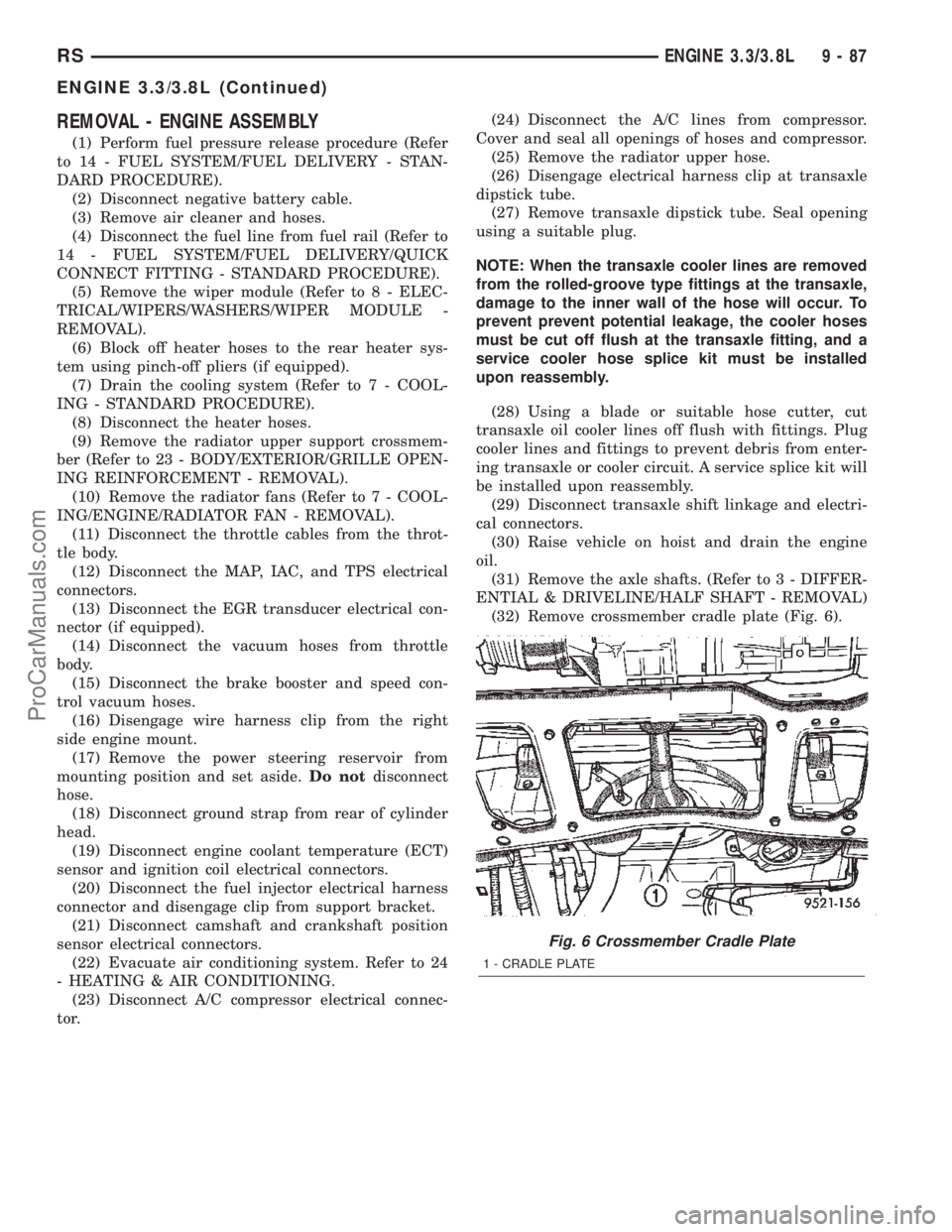
(32) Remove crossmember cradle plate (Fig. 6).
Fig. 6 Crossmember Cradle Plate
1 - CRADLE PLATE
RSENGINE 3.3/3.8L9-87
ENGINE 3.3/3.8L (Continued)
ProCarManuals.com
Page 1290 of 2399

(48) Remove the water pump pulley attaching
bolts and position pulley between pump hub and
housing.
(49) Disconnect the oil pressure switch electrical
connector.
(50) Disconnect wiring harness support clip from
engine oil dipstick tube.
(51) Install Special Tools 6912 and 8444 Adapters
on the right side (rear) of engine block (Fig. 9).
(52) Lower the vehicle.
(53) Remove the power steering pump and set
aside.
(54) Raise vehicle enough to allow engine dolly
Special Tool 6135 and cradle Special Tool 6710 with
post Special Tool 6848 and adaptor Special Tool 6909
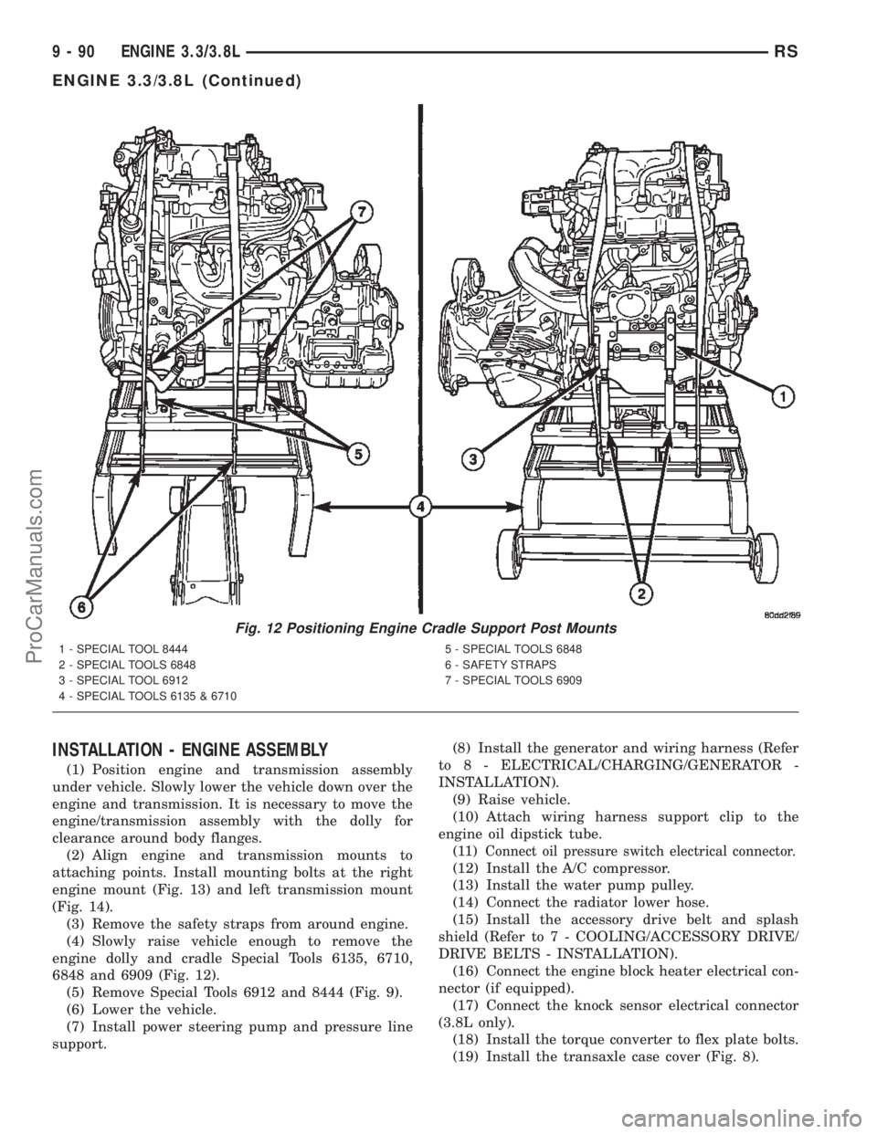
to be installed under vehicle (Fig. 12).
(55) Loosen cradle/post mounts to allow movement
for positioning posts into locating holes on the engine
(Fig. 10) and (Fig. 11). Slowly lower vehicle and posi-
tion cradle/post mounts until the engine is resting on
posts. Tighten all cradle/post mounts to cradle frame.
This will keep mounts from moving when removing
or installing engine and transmission.(56) Lower vehicle so the weight ofONLY THE
ENGINE AND TRANSMISSIONis on the cradle.
(57) Install and secure the safety straps to the cra-
dle fixture and around the engine (Fig. 12).
(58) Remove the engine right side mount to engine
attaching bolts (Fig. 13).
(59) Remove the left mount through bolt (Fig. 14).
(60) Raise vehicle slowly. It is necessary to move
the engine/transmission assembly with the dolly to
allow for removal around body flanges.
Fig. 9 ADAPTER TOOLS MOUNTED ON BLOCK
1 - SPECIAL TOOL 6912
2 - SPECIAL TOOL 8444
Fig. 10 Positioning Special Tool 6848 for use with
Adapters 8444 & 6912
1 - SLOTS
2 - SPECIAL TOOLS 6848
Fig. 11 Special Tools 6848 with Adapters 6909
1 - OIL FILTER
2 - SPECIAL TOOLS 6909
3 - OIL PAN
4 - SPECIAL TOOLS 6848
RSENGINE 3.3/3.8L9-89
ENGINE 3.3/3.8L (Continued)
ProCarManuals.com
Page 1291 of 2399
INSTALLATION - ENGINE ASSEMBLY
(1) Position engine and transmission assembly
under vehicle. Slowly lower the vehicle down over the
engine and transmission. It is necessary to move the
engine/transmission assembly with the dolly for
clearance around body flanges.
(2) Align engine and transmission mounts to
attaching points. Install mounting bolts at the right
engine mount (Fig. 13) and left transmission mount
(Fig. 14).
(3) Remove the safety straps from around engine.
(4) Slowly raise vehicle enough to remove the
engine dolly and cradle Special Tools 6135, 6710,
6848 and 6909 (Fig. 12).
(5) Remove Special Tools 6912 and 8444 (Fig. 9).
(6) Lower the vehicle.
(7) Install power steering pump and pressure line
support.(8) Install the generator and wiring harness (Refer
to 8 - ELECTRICAL/CHARGING/GENERATOR -
INSTALLATION).
(9) Raise vehicle.
(10) Attach wiring harness support clip to the
engine oil dipstick tube.
(11)
Connect oil pressure switch electrical connector.
(12) Install the A/C compressor.
(13) Install the water pump pulley.
(14) Connect the radiator lower hose.
(15) Install the accessory drive belt and splash
shield (Refer to 7 - COOLING/ACCESSORY DRIVE/
DRIVE BELTS - INSTALLATION).
(16) Connect the engine block heater electrical con-
nector (if equipped).
(17) Connect the knock sensor electrical connector
(3.8L only).
(18) Install the torque converter to flex plate bolts.
(19) Install the transaxle case cover (Fig. 8).
Fig. 12 Positioning Engine Cradle Support Post Mounts
1 - SPECIAL TOOL 8444
2 - SPECIAL TOOLS 6848
3 - SPECIAL TOOL 6912
4 - SPECIAL TOOLS 6135 & 67105 - SPECIAL TOOLS 6848
6 - SAFETY STRAPS
7 - SPECIAL TOOLS 6909
9 - 90 ENGINE 3.3/3.8LRS
ENGINE 3.3/3.8L (Continued)
ProCarManuals.com
Page 1296 of 2399
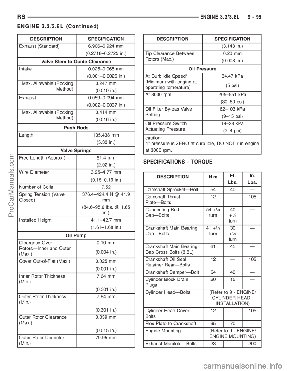
DESCRIPTION SPECIFICATION
Exhaust (Standard) 6.906±6.924 mm
(0.2718±0.2725 in.)
Valve Stem to Guide Clearance
Intake 0.025±0.065 mm
(0.001±0.0025 in.)
Max. Allowable (Rocking
Method)0.247 mm
(0.010 in.)
Exhaust 0.059±0.094 mm
(0.002±0.0037 in.)
Max. Allowable (Rocking
Method)0.414 mm
(0.016 in.)
Push Rods
Length 135.438 mm
(5.33 in.)
Valve Springs
Free Length (Approx.) 51.4 mm
(2.02 in.)
Wire Diameter 3.95±4.77 mm
(0.15±0.19 in.)
Number of Coils 7.52
Spring Tension (Valve
Closed)376.4±424.4 N @ 41.9
mm
(84.6±95.6 lbs. @ 1.65
in.)
Installed Height 41.1±42.7 mm
(1.61±1.68 in.)
Oil Pump
Clearance Over
RotorsÐInner and Outer
(Max.)0.10 mm
(0.004 in.)
Cover Out-of-Flat (Max.) 0.025 mm
(0.001 in.)
Inner Rotor Thickness
(Min.)7.64 mm
(0.301 in.)
Outer Rotor Thickness
(Min.)7.64 mm
(0.301 in.)
Outer Rotor Clearance
(Max.)0.039 mm
(0.015 in.)
Outer Rotor Diameter
(Min.)79.95 mmDESCRIPTION SPECIFICATION
(3.148 in.)
Tip Clearance Between
Rotors (Max.)0.20 mm
(0.008 in.)
Oil Pressure
At Curb Idle Speed*
(Minimum with engine at
operating temerature)34.47 kPa
(5 psi)
At 3000 rpm 205±551 kPa
(30±80 psi)
Oil Filter By-pas Valve
Setting62±103 kPa
(9±15 psi)
Oil Pressure Switch
Actuating Pressure14±28 kPa
(2±4 psi)
caution:
*If pressure is ZERO at curb idle, DO NOT run engine
at 3000 rpm.
SPECIFICATIONS - TORQUE
DESCRIPTION N´mFt.
Lbs.In.
Lbs.
Camshaft SprocketÐBolt 54 40 Ð
Camshaft Thrust
PlateÐBolts12 Ð 105
Connecting Rod
CapÐBolts54 +
1¤4
turn40
+1¤4
turnÐ
Crankshaft Main Bearing
CapÐBolts41 +
1¤4
turn30
+1¤4
turnÐ
Crankshaft Main Bearing
Cap Cross Bolts (3.8L)61 45 Ð
Crankshaft Oil Seal
Retainer RearÐBolts12 Ð 105
Crankshaft DamperÐBolt 54 40 Ð
Cylinder Block Drain
Plugs20 15 Ð
Cylinder HeadÐBolts (Refer to 9 - ENGINE/
CYLINDER HEAD -
INSTALLATION)
Cylinder Head CoverÐ
Bolts12 Ð 105
Flex Plate to Crankshaft 95 70 Ð
Engine Mounting (Refer to 9 - ENGINE/
ENGINE MOUNTING)
Exhaust ManifoldÐBolts 23 Ð 200
RSENGINE 3.3/3.8L9-95
ENGINE 3.3/3.8L (Continued)
ProCarManuals.com
Page 1297 of 2399
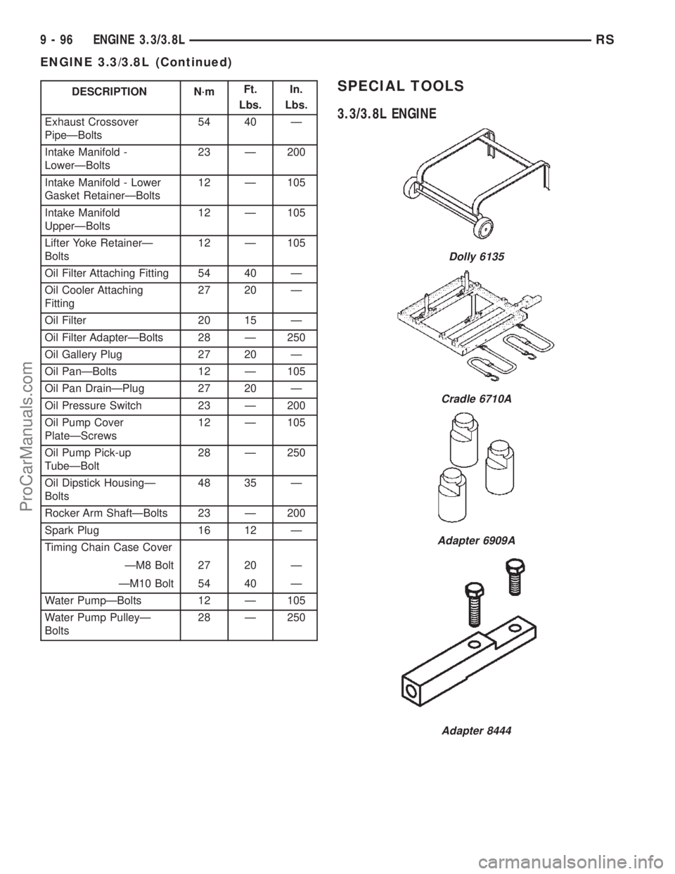
DESCRIPTION N´mFt.
Lbs.In.
Lbs.
Exhaust Crossover
PipeÐBolts54 40 Ð
Intake Manifold -
LowerÐBolts23 Ð 200
Intake Manifold - Lower
Gasket RetainerÐBolts12 Ð 105
Intake Manifold
UpperÐBolts12 Ð 105
Lifter Yoke RetainerÐ
Bolts12 Ð 105
Oil Filter Attaching Fitting 54 40 Ð
Oil Cooler Attaching
Fitting27 20 Ð
Oil Filter 20 15 Ð
Oil Filter AdapterÐBolts 28 Ð 250
Oil Gallery Plug 27 20 Ð
Oil PanÐBolts 12 Ð 105
Oil Pan DrainÐPlug 27 20 Ð
Oil Pressure Switch 23 Ð 200
Oil Pump Cover
PlateÐScrews12 Ð 105
Oil Pump Pick-up
TubeÐBolt28 Ð 250
Oil Dipstick HousingÐ
Bolts48 35 Ð
Rocker Arm ShaftÐBolts 23 Ð 200
Spark Plug 16 12 Ð
Timing Chain Case Cover
ÐM8 Bolt 27 20 Ð
ÐM10 Bolt 54 40 Ð
Water PumpÐBolts 12 Ð 105
Water Pump PulleyÐ
Bolts28 Ð 250SPECIAL TOOLS
3.3/3.8L ENGINE
Dolly 6135
Cradle 6710A
Adapter 6909A
Adapter 8444
9 - 96 ENGINE 3.3/3.8LRS
ENGINE 3.3/3.8L (Continued)
ProCarManuals.com
Page 1299 of 2399

Adapter, Valve Spring Compressor Off-vehicle 8464
Remover, Valve Tappet C-4129-A
Remover, Crankshaft Front Seal 6341A
Installer, Crankshaft Front Seal C-4992
Remover and Installer, Crankshaft Main Bearing
C-3059
Rear Crankshaft Oil Seal Installer 6926
Oil Pressure Gauge C-3292
Adapter 8406
Cooling System Tester 7700
Combustion Leak Tester C-3685-A
9 - 98 ENGINE 3.3/3.8LRS
ENGINE 3.3/3.8L (Continued)
ProCarManuals.com
Page 1311 of 2399
(2) Follow the same procedure on the remaining 5
cylinders using the firing sequence 1-2-3-4-5-6.Make
sure piston in cylinder is at TDC on the valve
spring that is being covered.
(3) Remove spark plug adapter tool.
(4) Install rocker arms and shaft assembly. (Refer
to 9 - ENGINE/CYLINDER HEAD/ROCKER ARMS -
INSTALLATION)
(5) Install cylinder head covers. (Refer to 9 -
ENGINE/CYLINDER HEAD/CYLINDER HEAD
COVER(S) - INSTALLATION)
(6) Install spark plugs and connect wires.
(7) Connect negative cable to battery.
ROCKER ARMS
DESCRIPTION
DESCRIPTION - ROCKER ARMS
The rocker arms are installed on the rocker arm
shaft. The rocker arms and shaft assembly is
attached to the cylinder head with seven bolts and
retainers. The rocker arms are made of stamped
steel.
DESCRIPTION - PUSHRODS
The pushrods are made of steel and are a hollow
design. The pushrods are positioned between the
hydraulic lifter and the rocker arm.
OPERATION
OPERATION - ROCKER ARMS
The rocker arm pivots on the rocker shaft. Rocker
arms are used to translate up and down motions pro-
vided by the camshaft, hydraulic lifter, and pushrod
on one end, into a down and up motions on the valve
stem on the opposing end.
OPERATION - PUSHRODS
The pushrod is a solid link between the hydraulic
lifter and the rocker arm. Also, the pushrod supplies
engine oil from the hydraulic lifter to the rocker arm.
REMOVAL - ROCKER ARMS AND SHAFT
(1) Remove the cylinder head cover(s). (Refer to 9 -
ENGINE/CYLINDER HEAD/CYLINDER HEAD
COVER(S) - REMOVAL)
NOTE: Rocker arm shaft bolts are captured to the
shaft.
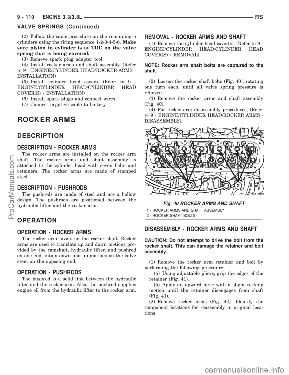
(2) Loosen the rocker shaft bolts (Fig. 40), rotating
one turn each, until all valve spring pressure is
relieved.
(3) Remove the rocker arms and shaft assembly
(Fig. 40).
(4) For rocker arm disassembly procedures, (Refer
to 9 - ENGINE/CYLINDER HEAD/ROCKER ARMS -
DISASSEMBLY).
DISASSEMBLY - ROCKER ARMS AND SHAFT
CAUTION: Do not attempt to drive the bolt from the
rocker shaft. This can damage the retainer and bolt
assembly.
(1) Remove the rocker arm retainer and bolt by
performing the following procedure:
(a) Using adjustable pliers, grip the edges of the
retainer (Fig. 41).
(b) Apply an upward force with a slight rocking
motion until the retainer disengages from shaft
(Fig. 41).
(2) Remove rocker arms (Fig. 42). Identify the
component locations for reassembly in original loca-
tions.
Fig. 40 ROCKER ARMS AND SHAFT
1 - ROCKER ARMS AND SHAFT ASSEMBLY
2 - ROCKER SHAFT BOLTS
9 - 110 ENGINE 3.3/3.8LRS
VALVE SPRINGS (Continued)
ProCarManuals.com
Page 1326 of 2399
(3) Install flex plate bolts (Fig. 70). Tighten bolts
to 95 N´m (70 ft. lbs.).
(4) Install the transaxle (Refer to 21 - TRANSMIS-
SION/TRANSAXLE/AUTOMATIC - 41TE - INSTAL-
LATION).
HYDRAULIC LIFTERS (CAM IN
BLOCK)
DESCRIPTION
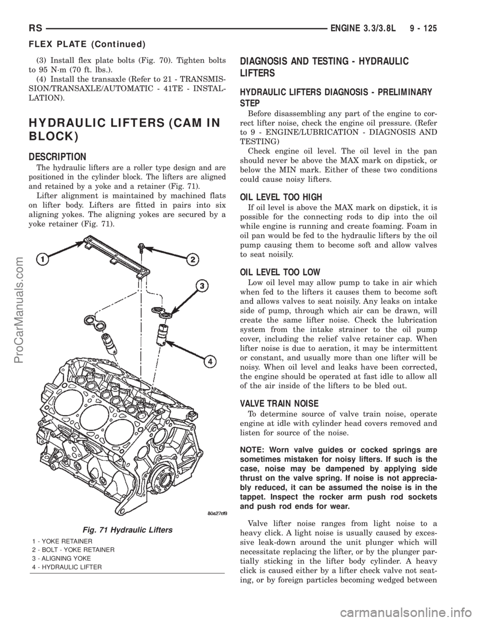
The hydraulic lifters are a roller type design and are
positioned in the cylinder block. The lifters are aligned
and retained by a yoke and a retainer (Fig. 71).
Lifter alignment is maintained by machined flats
on lifter body. Lifters are fitted in pairs into six
aligning yokes. The aligning yokes are secured by a
yoke retainer (Fig. 71).
DIAGNOSIS AND TESTING - HYDRAULIC
LIFTERS
HYDRAULIC LIFTERS DIAGNOSIS - PRELIMINARY
STEP
Before disassembling any part of the engine to cor-
rect lifter noise, check the engine oil pressure. (Refer
to 9 - ENGINE/LUBRICATION - DIAGNOSIS AND
TESTING)
Check engine oil level. The oil level in the pan
should never be above the MAX mark on dipstick, or
below the MIN mark. Either of these two conditions
could cause noisy lifters.
OIL LEVEL TOO HIGH
If oil level is above the MAX mark on dipstick, it is
possible for the connecting rods to dip into the oil
while engine is running and create foaming. Foam in
oil pan would be fed to the hydraulic lifters by the oil
pump causing them to become soft and allow valves
to seat noisily.
OIL LEVEL TOO LOW
Low oil level may allow pump to take in air which
when fed to the lifters it causes them to become soft
and allows valves to seat noisily. Any leaks on intake
side of pump, through which air can be drawn, will
create the same lifter noise. Check the lubrication
system from the intake strainer to the oil pump
cover, including the relief valve retainer cap. When
lifter noise is due to aeration, it may be intermittent
or constant, and usually more than one lifter will be
noisy. When oil level and leaks have been corrected,
the engine should be operated at fast idle to allow all
of the air inside of the lifters to be bled out.
VALVE TRAIN NOISE
To determine source of valve train noise, operate
engine at idle with cylinder head covers removed and
listen for source of the noise.
NOTE: Worn valve guides or cocked springs are
sometimes mistaken for noisy lifters. If such is the
case, noise may be dampened by applying side
thrust on the valve spring. If noise is not apprecia-
bly reduced, it can be assumed the noise is in the
tappet. Inspect the rocker arm push rod sockets
and push rod ends for wear.
Valve lifter noise ranges from light noise to a
heavy click. A light noise is usually caused by exces-
sive leak-down around the unit plunger which will
necessitate replacing the lifter, or by the plunger par-
tially sticking in the lifter body cylinder. A heavy
click is caused either by a lifter check valve not seat-
ing, or by foreign particles becoming wedged between
Fig. 71 Hydraulic Lifters
1 - YOKE RETAINER
2 - BOLT - YOKE RETAINER
3 - ALIGNING YOKE
4 - HYDRAULIC LIFTER
RSENGINE 3.3/3.8L9 - 125
FLEX PLATE (Continued)
ProCarManuals.com