Page 319 of 497
4-91 Trailer Wiring Harness
Your vehicle is equipped with one of the following
wiring harnesses for towing a trailer or hauling a
slide
-in camper.
Basic Trailer Wiring Package
All regular, extended cab crew cab pickups have a
six
-wire trailer towing harness.
The six-wire harness is located at the rear of the vehicle
and is tied to the vehicle's frame. The harness requires
the installation of a trailer
-wiring harness connector,
which is available through your dealer.
The six
-wire harness contains the following
trailer circuits:
�Yellow: Left Stop/Turn Signal
�Dark Green: Right Stop/Turn Signal
�Brown: Taillamps
�White: Ground
�Light Green: Back
-up Lamps
�Light Blue: Center High
-Mounted
Stoplamp (CHMSL)
If you need to upgrade your vehicle to heavy
-duty
trailering, a brake controller harness and an underbody
harness with a seven
-pin universal heavy-duty trailer
connector are available from your dealer.
Page 320 of 497
4-92
Heavy-Duty Trailer Wiring Package (If Equipped)
Your pickup may be equipped with the eight-wire trailer
towing harness. This harness with a seven
-pin universal
heavy
-duty trailer connector is attached to a bracket on
the platform hitch.*
* The Center High
-Mounted Stoplamp (CHMSL) wire
is tied next to the trailer wiring harness for use with a
trailer, slide
-in camper or cap.The eight
-wire harness contains the following
trailer circuits:
�Yellow: Left Stop/Turn Signal
�Dark Green: Right Stop/Turn Signal
�Brown: Taillamps
�White: Ground
�Light Green: Back
-up Lamps
�Light Blue: CHMSL
�Red: Battery Feed
�Dark Blue: Trailer Brake
A jumper harness for an electric trailer brake controller
and a trailer battery feed fuse are included with this
trailering package. (See ªInstrument Panel Jumper
Wiring Harnessº later in this section.)
If you need to tow a light
-duty trailer with a standard
four
-way round pin connector, an adapter connector is
included with your vehicle.
Page 321 of 497

4-93
Camper/Fifth-Wheel Trailer Wiring Package
(If Equipped)
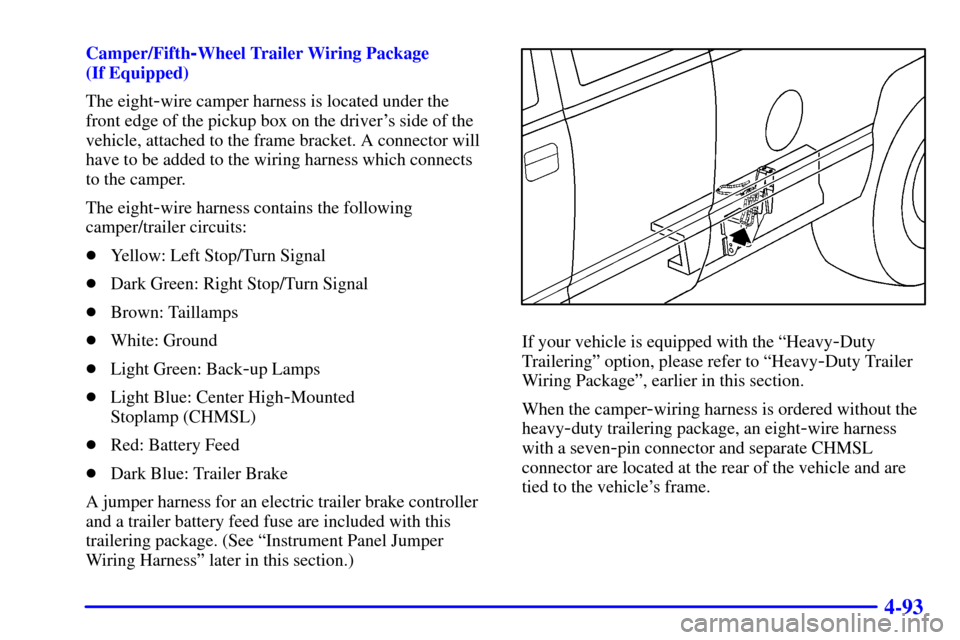
The eight
-wire camper harness is located under the
front edge of the pickup box on the driver's side of the
vehicle, attached to the frame bracket. A connector will
have to be added to the wiring harness which connects
to the camper.
The eight
-wire harness contains the following
camper/trailer circuits:
�Yellow: Left Stop/Turn Signal
�Dark Green: Right Stop/Turn Signal
�Brown: Taillamps
�White: Ground
�Light Green: Back
-up Lamps
�Light Blue: Center High
-Mounted
Stoplamp (CHMSL)
�Red: Battery Feed
�Dark Blue: Trailer Brake
A jumper harness for an electric trailer brake controller
and a trailer battery feed fuse are included with this
trailering package. (See ªInstrument Panel Jumper
Wiring Harnessº later in this section.)
If your vehicle is equipped with the ªHeavy-Duty
Traileringº option, please refer to ªHeavy
-Duty Trailer
Wiring Packageº, earlier in this section.
When the camper
-wiring harness is ordered without the
heavy
-duty trailering package, an eight-wire harness
with a seven
-pin connector and separate CHMSL
connector are located at the rear of the vehicle and are
tied to the vehicle's frame.
Page 322 of 497
4-94
Instrument Panel Jumper Wiring Harness
This harness is included with the heavy-duty and
camper/fifth
-wheel trailer wiring packages. The harness
is for an electric trailer brake controller and includes a
trailer battery feed fuse. This harness and fuse should be
installed by your dealer or a qualified service center.Four Wire Trailer Harness Adapter
If you need to tow a light
-duty trailer with a standard
four
-way round pin connector, an adapter connector is
included with your vehicle.
Connect the adapter with
the tab (arrow) pointing
towards the top. The cap
on the wiring harness will
lock onto the tab (arrow)
and help hold the adapter
in place.
Page 324 of 497

4-96 Power Winches
If you wish to use a power winch on your vehicle, only
use it when your vehicle is stationary or anchored.
NOTICE:
Using a power winch with the transmission in
gear may damage the transmission. When
operating a power winch, always leave the
transmission in NEUTRAL (N).
Use the regular brakes, set the parking brake, or block
the wheels to keep your vehicle from rolling.
Power Take-Off (PTO) (If Equipped)
Before using a PTO, refer to the manufacturer's or
installer's instructions.
To engage a PTO on a vehicle with a manual
transmission do the following:
1. Hold the clutch pedal down.
2. Set the parking brake.3. Shift the transmission into NEUTRAL (N).
4. Engage the PTO. Refer to the manufacturer's
or installer's for instructions on electrically
engaged PTOs.
5. For mobile operations, shift the transmission into the
gear you want, apply the regular brakes and release
the parking brake. For stationary operations, leave
the parking brake applied.
6. Release the clutch and regular brakes as you
normally would. When the clutch is released, the
PTO will start.
7. Turn the PTO rotary switch to ON.
To engage a PTO on a vehicle with an automatic
transmission do the following:
1. For stationary use shift the transmission
into PARK (P).
2. Turn the PTO rotary switch ON.
3. If the engine speed is below the PTO engage speed
limit, the PTO will start. The blinking LED on the
PTO control switch indicates PTO engage is
requested. When PTO engages the LED will switch
from blinking to a steady light.
Page 330 of 497

5-4
2. If you have a vehicle with a diesel engine with two
batteries (or more), you should know before you
begin that, especially in cold weather, you may not
be able to get enough power from a single battery in
another vehicle to start your diesel engine.
If your vehicle has more than one battery, use the
battery that's closer to the starter
-- this will reduce
electrical resistance.
3. Get the vehicles close enough so the jumper cables
can reach, but be sure the vehicles aren't touching
each other. If they are, it could cause a ground
connection you don't want. You wouldn't be able to
start your vehicle, and the bad grounding could
damage the electrical systems.
To avoid the possibility of the vehicles rolling, set
the parking brake firmly on both vehicles involved
in the jump start procedure. Put an automatic
transmission in PARK (P) or a manual transmission
in NEUTRAL before setting the parking brake. If
you have a four
-wheel-drive vehicle, be sure the
transfer case is in a drive gear not in NEUTRAL.
NOTICE:
If you leave your radio on, it could be badly
damaged. The repairs wouldn't be covered by
your warranty.
4. Turn off the ignition on both vehicles. Unplug
unnecessary accessories plugged into the cigarette
lighter or accessory power outlets. Turn off the radio
and all lamps that aren't needed. This will avoid
sparks and help save both batteries. And it could
save your radio!
Page 409 of 497

6-44 Brake Wear
Your vehicle has four-wheel disc brakes.
Disc brake pads have built
-in wear indicators that
make a high
-pitched warning sound when the brake
pads are worn and new pads are needed. The sound may
come and go or be heard all the time your vehicle is
moving (except when you are pushing on the brake
pedal firmly).
CAUTION:
The brake wear warning sound means that soon
your brakes won't work well. That could lead to
an accident. When you hear the brake wear
warning sound, have your vehicle serviced.
NOTICE:
Continuing to drive with worn-out brake pads
could result in costly brake repair.
Some driving conditions or climates may cause a brake
squeal when the brakes are first applied or lightly
applied. This does not mean something is wrong with
your brakes.
Properly torqued wheel nuts are necessary to help
prevent brake pulsation. When tires are rotated, inspect
brake pads for wear and evenly tighten wheel nuts in the
proper sequence to GM torque specifications.
Brake linings should always be replaced as complete
axle sets.
See ªBrake System Inspectionº in Section 7 of this manual
under Part C ªPeriodic Maintenance Inspections.º
Brake Pedal Travel
See your dealer if the brake pedal does not return to
normal height, or if there is a rapid increase in pedal
travel. This could be a sign of brake trouble.
Brake Adjustment
Every time you make a brake stop, your disc brakes
adjust for wear.
Page 445 of 497
6-80
Center Instrument Panel Fuse Block
The center instrument panel utility block is located
underneath the instrument panel, to the left of the
steering column.Relay Name Usage
SEO Special Equipment Option
HTD ST Heated Seats
SPARE 4 Not Used
VANITY Headliner Wiring
TRAILER Trailer Brake Wiring
PWR ST Power Seats
SPARE 5 Not Used
CLUTCH Manual Transmission
Clutch Switch
UPF Upfitter
PARK LAMP Parking Lamps (Relay)
FRT PRK EXPT Not Used (Fuse)
SL RIDE Manual Selectable Ride Switch
SPARE 2 Not Used
RR PRK LP Not Used (Relay)
RR FOG LP Not Used (Relay)
SPARE 3 Not Used
INADV PWR Interior Lights Feed
CTSY LP Courtesy Lamps
CEL PHONE Cellular Telephone Wiring