Page 1534 of 5127
Hold Mode
If your vehicle’s transaxle has hold mode, you can
select this mode to drive with some characteristics of
a manual transaxle. With hold mode turned on, the
automatic transaxle will stay in a specific gear range.
Press the HOLD button on the shift lever console to turn
on hold mode. Press the button again to turn off hold
mode, and return to normal automatic transaxle
operation.While on, the HOLD indicator light on the secondary
information center will light up. SeeHold Mode Light on
page 3-28.
When hold mode is activated, the transaxle is fixed in
the gear selected.
Hold Mode Features
Winter Function
Select hold mode while in AUTOMATIC
OVERDRIVE (D4) to help the vehicle maintain
traction on slippery road surfaces, such as snow,
mud, or ice.
Manually Controlling Shift
Select hold mode to use your automatic transaxle like
a three-speed manual transaxle.
2-25
Page 1545 of 5127
Storage Areas
Your vehicle has shopping hooks on each front seatback
for your convenience.
Glove Box
Open the glove box by pulling the bottom of the handle
upward. Close the glove box with a firm push.
Cupholder(s)
The cupholders are located in the center instrument
panel, below the climate control system. To use
the cupholder, push in on its outer edge. Then pull out
the cupholder. After use, push in the cupholder until
it latches.
There is also a cupholder located in the rear part of the
center console, behind the parking brake.
2-36
Page 1558 of 5127

The switches have three positions.
ON:The light comes on and stays on regardless of
whether a door is open or closed.
O(Door):The light comes on when a door is opened.
The light turns off when all the doors are shut.
OFF:The light remains off even when a door is opened.
Accessory Power Outlets
With the accessory power outlet, you can plug in
auxiliary electrical equipment such as a cellular
telephone or CB radio.
The accessory power outlet is located next to the
parking brake on the center console.
To use the outlet, remove the protective cap. When not
in use, always cover the outlet with the protective
cap. The accessory power outlet is operational when
the ignition is turned to ACC or ON.
Notice:Leaving electrical equipment on for
extended periods will drain the battery. Always turn
off electrical equipment when not in use and do
not plug in equipment that exceeds the maximum
amperage rating.Certain electrical accessories may not be compatible
with the accessory power outlet and could result
in blown vehicle or adapter fuses. If you experience a
problem, see your dealer for additional information
on accessory power outlets.
Notice:Adding any electrical equipment to your
vehicle may damage it or keep other components
from working as they should. The repairs would not
be covered by your warranty. Check with your
dealer before adding electrical equipment.
When adding electrical equipment, be sure to follow
the proper installation instructions included with
the equipment.
Notice:Improper use of the power outlet can cause
damage not covered by your warranty. Do not
hang any type of accessory or accessory bracket
from the plug because the power outlets are
designed for accessory power plugs only.
3-11
Page 1879 of 5127
Hold Mode
If your vehicle’s transaxle has hold mode, you can
select this mode to drive with some characteristics of a
manual transaxle. With hold mode turned on, the
automatic transaxle will stay in a specific gear range.
Press the HOLD button on the shift lever console to turn
on hold mode. Press the button again to turn off hold
mode, and return to normal automatic transaxle
operation.While on, the HOLD light on the secondary information
center will light up. SeeHold Mode Light on page 3-34.
When hold mode is activated, the transaxle is fixed
in the gear selected.
Hold Mode Features
Winter Function
Select hold mode while in AUTOMATIC
OVERDRIVE (D4) to help the vehicle maintain traction on
slippery road surfaces, such as snow, mud, or ice.
Manually Controlling Shift
Select hold mode to use your automatic transaxle like a
three-speed manual transaxle.
2-24
Page 1889 of 5127
Storage Areas
Your vehicle has shopping hooks on each front seatback
for your convenience. Lift the headrest to access
the hooks.
Glove Box
Open the glove box by pulling the bottom of the handle
upward.
Cupholder(s)
The two cupholders are located in the center instrument
panel, below the climate control system. To use the
cupholder, push in on its outer edge. Then pull out the
cupholder. After use, push in the cupholder until it
latches.
There is also a cupholder located in the rear part of the
center console, behind the parking brake.
2-34
Page 1907 of 5127
Dome Lamp
Your vehicle will have one of the following dome lamp
switches.
The switches have three positions.
ON:The light comes on and stays on.
O(Door):The light comes on when a door is opened.
The light turns off when all the doors are closed.
OFF:The light remains off even when a door is opened.
Accessory Power Outlet(s)
With the accessory power outlet, you can plug in
auxiliary electrical equipment such as a cellular
telephone or CB radio.
The accessory power outlet is located next to the
parking brake on the center console.
To use the outlet, remove the protective cap. When not
in use, always cover the outlet with the protective
cap. The accessory power outlet is operational when
the ignition is turned to ACC or ON.
Notice:Leaving electrical equipment on for
extended periods will drain the battery. Always turn
off electrical equipment when not in use and do
not plug in equipment that exceeds the maximum
amperage rating.
Without Sunroof
With Sunroof
3-16
Page 4319 of 5127

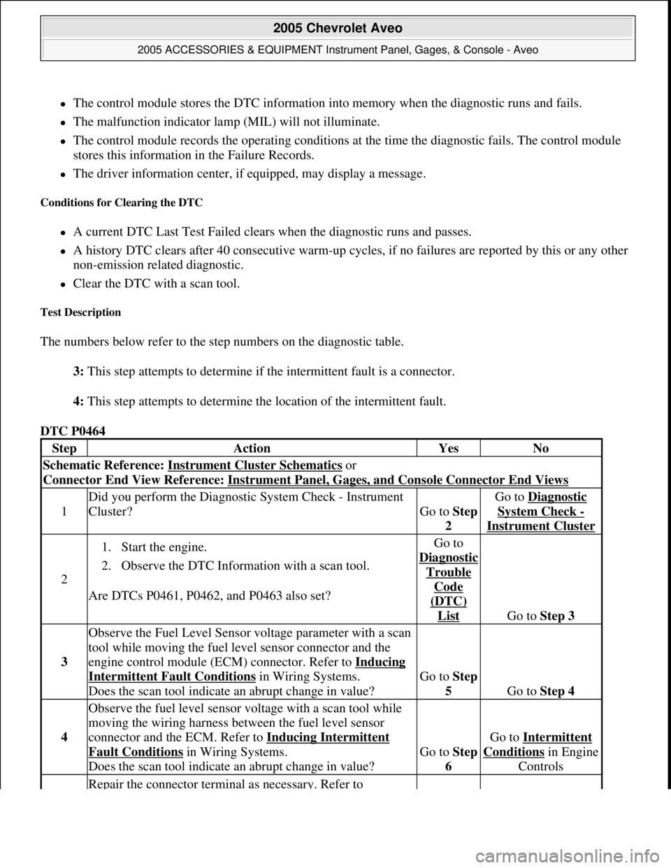
The control module stores the DTC information into memory when the diagnostic runs and fails.
The malfunction indicator lamp (MIL) will not illuminate.
The control module records the operating conditions at the time the diagnostic fails. The control module
stores this information in the Failure Records.
The driver information center, if equipped, may display a message.
Conditions for Clearing the DTC
A current DTC Last Test Failed clears when the diagnostic runs and passes.
A history DTC clears after 40 consecutive warm-up cycles, if no failures are reported by this or any other
non-emission related diagnostic.
Clear the DTC with a scan tool.
Test Description
The numbers below refer to the step numbers on the diagnostic table.
3: This step attempts to determine if the intermittent fault is a connector.
4: This step attempts to determine the location of the intermittent fault.
DTC P0464
StepActionYesNo
Schematic Reference: Instrument Cluster Schematics or
Connector End View Reference: Instrument Panel, Gages, and Console Connector End Views
1
Did you perform the Diagnostic System Check - Instrument
Cluster?
Go to Step
2
Go to Diagnostic
System Check -
Instrument Cluster
2
1. Start the engine.
2. Observe the DTC Information with a scan tool.
Are DTCs P0461, P0462, and P0463 also set?Go to
Dia
gnostic
Trouble
Code
(DTC)
List Go to Step 3
3
Observe the Fuel Level Sensor voltage parameter with a scan
tool while moving the fuel level sensor connector and the
engine control module (ECM) connector. Refer to Inducing
Intermittent Fault Conditions in Wiring Systems.
Does the scan tool indicate an abrupt change in value?Go to Step
5
Go to Step 4
4
Observe the fuel level sensor voltage with a scan tool while
moving the wiring harness between the fuel level sensor
connector and the ECM. Refer to Inducing Intermittent
Fault Conditions in Wiring Systems.
Does the scan tool indicate an abrupt change in value?Go to Step
6
Go to Intermittent
Conditionsin Engine
Controls
Repair the connector terminal as necessary. Refer to
2005 Chevrolet Aveo
2005 ACCESSORIES & EQUIPMENT Instrument Panel, Gages, & Console - Aveo
Microsoft
Friday, July 31, 2009 1:07:02 PMPage 26 © 2005 Mitchell Repair Information Company, LLC.
Page 4332 of 5127
Fig. 11: View of Chime Module and Screws
Courtesy of GENERAL MOTORS CORP.
1. Connect the electrical connector.
2. Install the chime module with the screws.
Tighten: Tighten the chime module screws to 3.5 N.m (31 lb in).
3. Connect the negative battery cable.
TRIM PANEL REPLACEMENT - INSTRUMENT PANEL (I/P) CENTER
NOTE: Refer to Fastener Notice in Cautions and Notices.
2005 Chevrolet Aveo
2005 ACCESSORIES & EQUIPMENT Instrument Panel, Gages, & Console - Aveo
Microsoft
Friday, July 31, 2009 1:07:03 PMPage 39 © 2005 Mitchell Repair Information Company, LLC.