2002 CHEVROLET AVEO display
[x] Cancel search: displayPage 1958 of 5127
Root Directory
The root directory will be treated as a folder. If the root
directory has compressed audio files, the directory
will be displayed as ROOT. All files contained directly
under the root directory will be accessed prior to
any other directory.
Empty Directory or Folder
If a root directory or a folder exists somewhere in the
file structure that contains only folders/subfolders and no
compressed files directly beneath them, the player will
advance to the next folder in the file structure that
contains compressed audio files and the empty folder
will not be displayed or numbered.
No Folder
When the CD contains only compressed files, the files will
be located under the root folder. The next and previous
folder functions will have no function on a CD that was
recorded without folders or playlists. When displaying the
name of the folder the radio will display ROOT.
When the CD contains only compressed audio files, but
no folders, all files will be located under the root
folder. When the radio displays the name of the folder,
the radio will display ROOT.
Order of Play
Tracks will be played in the following order:
•Playback will begin from the first track under the
root directory.
•When all tracks from the root directory have been
played, playback will continue from files, according
to their numerical listing.
•After playing the last track from the last folder, the
player will begin playing again at the first track of
the first folder or root directory.
File System and Naming
The song name in the ID3 tag will be displayed. If the
song name is not present in the ID3 tag, then the
radio will display the file name without the extension
(such as MP3/WMA) instead.
Track names longer than 32 characters or 4 pages will
be shortened. The display will not show parts of
words on the last page of text and the extension of the
filename will not be displayed.
3-67
Page 1959 of 5127
Playing an MP3/WMA
With the ignition on, insert a CD partway into the slot,
label side up. The player will pull it in, Loading, then
Filecheck, and then MP3 or WMA will appear on
the display. The CD should begin playing. You cannot
insert a CD with the ACC off.
As each new track starts to play, the track number, and
the song name will appear on the display.
If the ignition or radio is turned off with a CD in the player,
it will stay in the player. When a CD is in the player and
the ignition is turned on, the radio must be turned on
before the CD will start playback. When the ignition and
radio are turned on, the CD will start playing where it
stopped, if it was the last selected audio source.
The CD player can play the smaller 3 inch (8 cm) single
CDs with an adapter ring. Full-size CDs and the
smaller CDs are loaded in the same manner.
If playing a CD-R, the sound quality may be reduced due
to CD-R quality, the method of recording, the quality of
the music that has been recorded, and the way the CD-R
has been handled. There may be an increase in skipping,
difficulty in finding tracks, and/or difficulty in loading and
ejecting. If these problems occur, check the bottom
surface of the CD. If the surface of the CD is damaged,
such as cracked, broken, or scratched, the CD will not
play properly. If the surface of the CD is soiled, seeCare
of Your CDs on page 3-71for more information.If there is no apparent damage, try a known good CD.
Do not add any label to a CD, it could get caught in the
CD player. If a CD is recorded on a personal computer
and a description label is needed, try labeling the top of
the recorded CD with a marking pen instead.
Notice:If you add any label to a CD, insert more
than one CD into the slot at a time, or attempt
to play scratched or damaged CDs, you could
damage the CD player. When using the CD player,
use only CDs in good condition without any
label, load one CD at a time, and keep the CD player
and the loading slot free of foreign materials,
liquids, and debris.
If an error appears on the display, see “CD Messages”
later in this section.
All of the CD functions work the same while playing an
MP3WMA, except for those listed here. See “Playing
a CD” earlier for more information.
SCROLL (MP3/WMA Mode Only):Press the SOUND
button for longer than two seconds. The song title
and other available information of the song will scroll
on/off. The offset is scroll on. The scroll mode can
be changed only when the SOUND button is pressed
for longer than two seconds.
3-68
Page 1960 of 5127
1 DIR (Directory):Press this button to repeat the
tracks in the current directory. DIR will appear on the
display.
Press this button again to repeat the tracks in all of the
directories. ALL will appear on the display.
Press this button again to turn off repeat play.
¦¥SEEK (Previous/Next Folder) (in MP3/WMA
Mode):Press the up or down arrows to change
the folder. If CD-R don’t have any folder, “ROOT” will
flash on display for a short time.
()TUNE (Previous/Next Track):Press the down
arrows to go to the start of the current track or press
the up arrows to go to the next track. The track number
will appear on the display. The player will continue
moving backward or forward through the CD with each
press of the up or down arrows.
INFO/DISP (Information/Display):Press this button to
display additional text information related to the
current MP3/WMA song. A choice of additional
information such as: Song Title, Album Title, and Artist.
Bit rate may also appear on display.
When information is not available, No Info will appear
on the display.
Press this button for longer than two seconds to change
display mode.
CD Messages
CHECK CD:If this message appears on the display
and/or the CD comes out, it could be for one of the
following reasons:
•It is very hot. When the temperature returns to
normal, the CD should play.
•You are driving on a very rough road. When the
road becomes smoother, the CD should play.
•The CD is dirty, scratched, wet, or upside down.
•The air is very humid. If so, wait about an hour and
try again.
•The format of the CD may not be compatible. See
“MP3 Format” earlier in this section.
•There may have been a problem while burning
the CD.
•The label may be caught in the CD player.
If the CD is not playing correctly, for any other reason,
try a known good CD.
If any error occurs repeatedly or if an error cannot be
corrected, contact your dealer. If the radio displays
an error message, write it down and provide it to your
dealer when reporting the problem.
3-69
Page 1961 of 5127
Using the Auxiliary Input Jack
Your radio system has an auxiliary input jack located on
the lower right side of the faceplate. This is not an
audio output; do not plug the headphone set into the
front auxiliary input jack. You can however, connect an
external audio device such as an iPod, laptop
computer, MP3 player, CD changer, or cassette tape
player, etc. to the auxiliary input jack for use as another
source for audio listening.
The auxiliary input jack will also accept cell phone
connectors. Plug the cell phone connector into
the auxiliary input jack to hear the other side of a cell
phone’s conversation through the vehicle sound system.
To use a portable audio player, connect a 3.5 mm
(1/8 inch) cable to the radio’s front auxiliary input jack.
When a device is connected, press the radio CD/AUX
button as needed to begin playing audio from the device
over the car speakers.
CD/AUX (CD/Auxiliary):Press this button once to play
a CD while a portable audio device is playing. Press
this button a second time for the system will begin
playing audio from the connected portable audio player.
Once in this mode, “Auxinput” will appear on display.
If the auxiliary jack does not detect the presence of an
output jack, the aux mode will be prevented from
coming up.
O(Power/Volume):Turn this knob clockwise or
counterclockwise to increase or decrease the volume of
the portable player. You may need to do additional
volume adjustments from the portable device if
the volume does not go loud or soft enough.
Radio Reception
You may experience frequency interference and static
during normal radio reception if items such as cellphone
chargers, vehicle convenience accessories, and
external electronic devices are plugged into the
accessory power outlet. If there is interference or static,
unplug the item from the accessory power outlet.
AM
The range for most AM stations is greater than for FM,
especially at night. The longer range can cause
station frequencies to interfere with each other. For
better radio reception, most AM radio stations will boost
the power levels during the day, and then reduce
these levels during the night. Static can also occur when
things like storms and power lines interfere with radio
reception. When this happens, try reducing the treble on
your radio.
3-70
Page 2106 of 5127
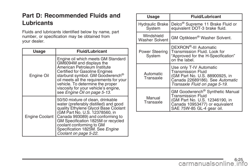
Part D: Recommended Fluids and
Lubricants
Fluids and lubricants identified below by name, part
number, or specification may be obtained from
your dealer.
Usage Fluid/Lubricant
Engine OilEngine oil which meets GM Standard
GM6094M and displays the
American Petroleum Institute
Certified for Gasoline Engines
starburst symbol. GM Goodwrench
®
oil meets all the requirements for your
vehicle. To determine the proper
viscosity for your vehicle’s engine,
seeEngine Oil on page 5-13.
Engine Coolant50/50 mixture of clean, drinkable
water (preferably distilled) and good
quality Ethylene Glycol Base Coolant
(GM Part No. U.S. 12378560, in
Canada 993089) and conforming to
GM Specification 1825M or recycled
coolant conforming to GM
Specification 1825M. SeeEngine
Coolant on page 5-22.
Usage Fluid/Lubricant
Hydraulic Brake
SystemDelco
®Supreme 11 Brake Fluid or
equivalent DOT-3 brake fluid.
Windshield
Washer SolventGM Optikleen
®Washer Solvent.
Power Steering
SystemDEXRON
®-III Automatic
Transmission Fluid. Look for
“Approved for the H-Specification”
on the label.
Automatic
TransaxleUse only T-IV Automatic
Transmission Fluid
(GM Part No. U.S. 88900925, in
Canada 22689186). SeeAutomatic
Transaxle Fluid on page 5-19.
Manual
TransaxleGM Goodwrench
®Synthetic Manual
Transmission Fluid
(GM Part No. U.S. 12346190, in
Canada 10953477) or equivalent
SAE 75W-85 GL-4 gear oil.
6-25
Page 2661 of 5127
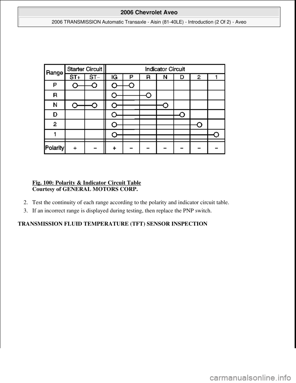
Fig. 100: Polarity & Indicator Circuit Table
Courtesy of GENERAL MOTORS CORP.
2. Test the continuity of each range according to the polarity and indicator circuit table.
3. If an incorrect range is displayed during testing, then replace the PNP switch.
TRANSMISSION FLUID TEMPERATURE (TFT) SENSOR INSPECTION
2006 Chevrolet Aveo
2006 TRANSMISSION Automatic Transaxle - Aisin (81-40LE) - Introduction (2 Of 2) - Aveo
Microsoft
Thursday, July 16, 2009 1:17:20 PMPage 112 © 2005 Mitchell Repair Information Company, LLC.
Page 4306 of 5127
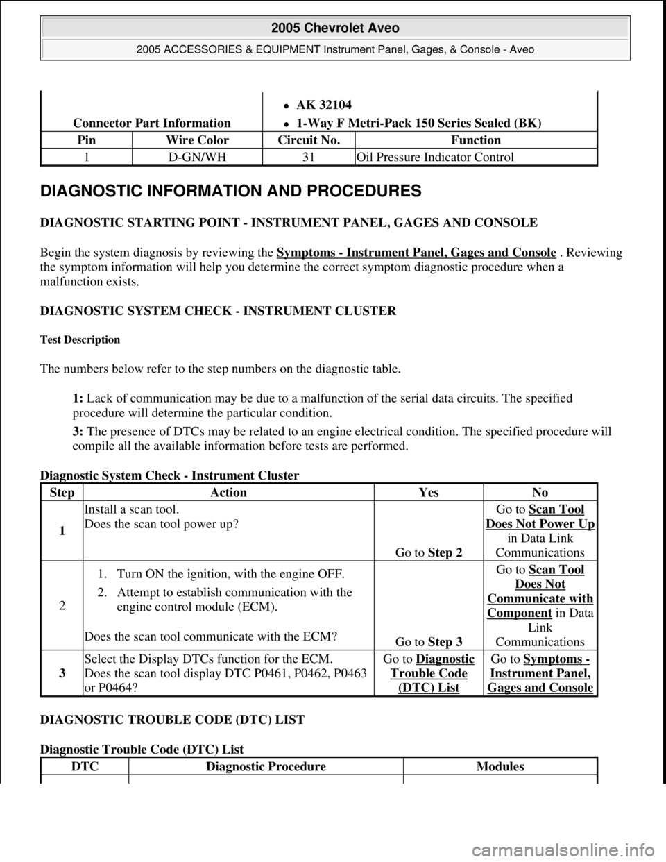
DIAGNOSTIC INFORMATION AND PROCEDURES
DIAGNOSTIC STARTING POINT - INSTRUMENT PANEL, GAGES AND CONSOLE
Begin the system diagnosis by reviewing the Symptoms
- Instrument Panel, Gages and Console . Reviewing
the symptom information will help you determine the correct symptom diagnostic procedure when a
malfunction exists.
DIAGNOSTIC SYSTEM CHECK - INSTRUMENT CLUSTER
Test Description
The numbers below refer to the step numbers on the diagnostic table.
1: Lack of communication may be due to a malfunction of the serial data circuits. The specified
procedure will determine the particular condition.
3: The presence of DTCs may be related to an engine electrical condition. The specified procedure will
compile all the available information before tests are performed.
Diagnostic System Check - Instrument Cluster
DIAGNOSTIC TROUBLE CODE (DTC) LIST
Diagnostic Trouble Code (DTC) List
Connector Part Information
AK 32104
1-Way F Metri-Pack 150 Series Sealed (BK)
PinWire ColorCircuit No.Function
1D-GN/WH31Oil Pressure Indicator Control
StepActionYesNo
1
Install a scan tool.
Does the scan tool power up?
Go to Step 2
Go to Scan Tool
Does Not Power Up
in Data Link
Communications
2
1. Turn ON the ignition, with the engine OFF.
2. Attempt to establish communication with the
engine control module (ECM).
Does the scan tool communicate with the ECM?
Go to Step 3
Go to Scan Tool
Does Not
Communicate with
Componentin Data
Link
Communications
3
Select the Display DTCs function for the ECM.
Does the scan tool display DTC P0461, P0462, P0463
or P0464?Go to Diagnostic
Trouble Code
(DTC) List
Go to Symptoms -
Instrument Panel,
Gages and Console
DTCDiagnostic ProcedureModules
2005 Chevrolet Aveo
2005 ACCESSORIES & EQUIPMENT Instrument Panel, Gages, & Console - Aveo
Microsoft
Friday, July 31, 2009 1:07:02 PMPage 13 © 2005 Mitchell Repair Information Company, LLC.
Page 4319 of 5127
The control module stores the DTC information into memory when the diagnostic runs and fails.
The malfunction indicator lamp (MIL) will not illuminate.
The control module records the operating conditions at the time the diagnostic fails. The control module
stores this information in the Failure Records.
The driver information center, if equipped, may display a message.
Conditions for Clearing the DTC
A current DTC Last Test Failed clears when the diagnostic runs and passes.
A history DTC clears after 40 consecutive warm-up cycles, if no failures are reported by this or any other
non-emission related diagnostic.
Clear the DTC with a scan tool.
Test Description
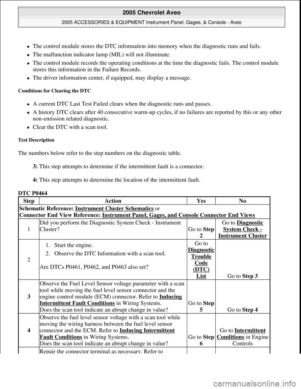
The numbers below refer to the step numbers on the diagnostic table.
3: This step attempts to determine if the intermittent fault is a connector.
4: This step attempts to determine the location of the intermittent fault.
DTC P0464
StepActionYesNo
Schematic Reference: Instrument Cluster Schematics or
Connector End View Reference: Instrument Panel, Gages, and Console Connector End Views
1
Did you perform the Diagnostic System Check - Instrument
Cluster?
Go to Step
2
Go to Diagnostic
System Check -
Instrument Cluster
2
1. Start the engine.
2. Observe the DTC Information with a scan tool.
Are DTCs P0461, P0462, and P0463 also set?Go to
Dia
gnostic
Trouble
Code
(DTC)
List Go to Step 3
3
Observe the Fuel Level Sensor voltage parameter with a scan
tool while moving the fuel level sensor connector and the
engine control module (ECM) connector. Refer to Inducing
Intermittent Fault Conditions in Wiring Systems.
Does the scan tool indicate an abrupt change in value?Go to Step
5
Go to Step 4
4
Observe the fuel level sensor voltage with a scan tool while
moving the wiring harness between the fuel level sensor
connector and the ECM. Refer to Inducing Intermittent
Fault Conditions in Wiring Systems.
Does the scan tool indicate an abrupt change in value?Go to Step
6
Go to Intermittent
Conditionsin Engine
Controls
Repair the connector terminal as necessary. Refer to
2005 Chevrolet Aveo
2005 ACCESSORIES & EQUIPMENT Instrument Panel, Gages, & Console - Aveo
Microsoft
Friday, July 31, 2009 1:07:02 PMPage 26 © 2005 Mitchell Repair Information Company, LLC.