Page 136 of 578

3-4
PRE-OPERATION INSPECTION AND MAINTENANCE
INSP
ADJ
EC320000
PRE-OPERATION INSPECTION AND MAINTENANCE
Before riding for break-in operation, practice or a race, make sure the machine is in good operating
condition.
Before using this machine, check the following points.
EC321000
GENERAL INSPECTION AND MAINTENANCE
Item Routine Page
Coolant Check that coolant is filled up to the radiator filler cap.
Check the cooling system for leakage.P3-5~9
Fuel Check that a fresh mixture of oil and gasoline is filled in
the fuel tank. Check the fuel line for leakage.P1-12
Transmission oil Check that the oil level is correct. Check the crankcase
for leakage.P3-12~14
Gear shifter and clutch Check that gears can be shifted correctly in order and
that the clutch operates smoothly.P3-9
Throttle grip/Housing Check that the throttle grip operation and free play
are correctly adjusted. Lubricate the throttle grip and P3-10~11
housing, if necessary.
Brakes Check the play of front brake and effect of front and
rear brake.P3-17~23
Chain Check chain slack and alignment. Check that the chain
is lubricated properly.P3-24~26
Wheels Check for excessive wear and tire pressure. Check for
loose spokes and have no excessive play.P3-34~35
Steering Check that the handlebar can be turned smoothly and
have no excessive play.P3-35~36
Front forks and Check that they operate smoothly and there is no oil
rear shock absorber leakage.P3-26~33
Cables (wires) Check that the clutch and throttle cables move smooth-
ly. Check that they are not caught when the handlebars —
are turned or when the front forks travel up and down.
Muffler Check that the muffler is tightly mounted and has no
cracks.P3-15~16
Sprocket Check that the driven sprocket tightening bolt is
not loose.P3-24
Lubrication Check for smooth operation. Lubricate if necessary. P3-37
Bolts and nuts Check the chassis and engine for loose bolts and nuts. P1-16
Lead connectors Check that the CDI magneto, CDI unit, and ignition coil
are connected tightly.P1-6
Settings Is the machine set suitably for the condition of the
racing course and weather or by taking into account the
P7-1~24
results of test runs before racing? Are inspection and
maintenance completely done?
5MW-9-30-3A 7/3/00 2:47 PM Page 14
Page 158 of 578

INSP
ADJ
3-14
PILOT AIR SCREW ADJUSTMENT
4. Remove:
9Oil drain bolt 1
9Oil filler cap 2
Drain the transmission oil.
5. Install:
9Aluminum washer
9Oil drain bolt 1
6. Fill:
9Transmission oil
Recommended oil:
Yamalube 4 (10W-30) or SAE
10W-30 type SE motor oil
Oil capacity
(periodic oil change):
0.75 L (0.66 Imp qt, 0.79 US qt)
20 Nm (2.0 m•kg, 14 ft•lb)
7. Check:
9Oil leakage
8. Check:
9Transmission oil level
9. Install:
9Oil filler cap 2
EC35L021
PILOT AIR SCREW ADJUSTMENT
1. Adjust:
9Pilot air screw 1
Adjusting steps:
9Turn in the pilot air screw until it is lightly
seated.
9Turn out the pilot air screw by the factory-set
number of turns.
NOTE:
To optimize the fuel flow at a smaller throttle
opening, each machine’s pilot air screw has
been individually set at the factory. Before
adjusting the pilot air screw, turn it in fully and
count the number of turns. Record this num-
ber as the factory-set number of turns out.
Pilot air screw:
1 turn out
*1-3/4 turns out
(for reference only)
*For EUROPE
5MW-9-30-3A 7/3/00 2:52 PM Page 36
Page 202 of 578
3-36
STEERING HEAD INSPECTION AND ADJUSTMENT
INSP
ADJ
9Loosen the ring nut one turn.
9Retighten the ring nut using the ring nut
wrench.
w
Avoid over-tightening.
9Check the steering shaft by turning it lock to
lock. If there is any binding, remove the
steering shaft assembly and inspect the
steering bearings.
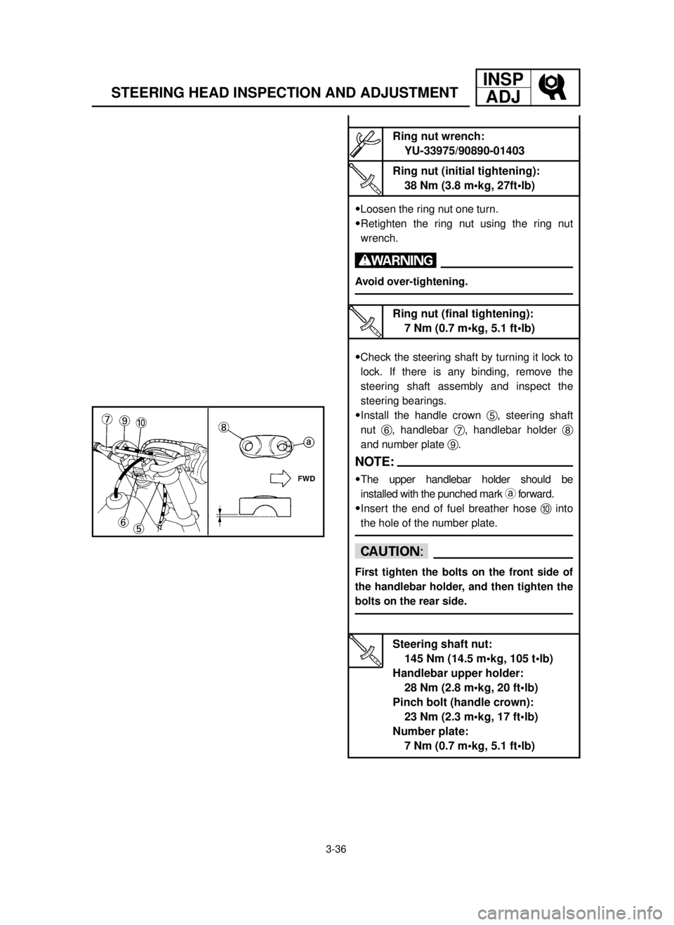
9Install the handle crown 5, steering shaft
nut 6, handlebar 7, handlebar holder 8
and number plate 9.
NOTE:
9The upper handlebar holder should be
installed with the punched mark aforward.
9Insert the end of fuel breather hose 0into
the hole of the number plate.
cC
First tighten the bolts on the front side of
the handlebar holder, and then tighten the
bolts on the rear side.
Ring nut wrench:
YU-33975/90890-01403
Ring nut (initial tightening):
38 Nm (3.8 m•kg, 27ft•lb)
Steering shaft nut:
145 Nm (14.5 m•kg, 105 t•lb)
Handlebar upper holder:
28 Nm (2.8 m•kg, 20 ft•lb)
Pinch bolt (handle crown):
23 Nm (2.3 m•kg, 17 ft•lb)
Number plate:
7 Nm (0.7 m•kg, 5.1 ft•lb)
Ring nut (final tightening):
7 Nm (0.7 m•kg, 5.1 ft•lb)
5MW-9-30-3B 7/3/00 3:29 PM Page 40
Page 212 of 578
4-1
SEAT, FUEL TANK AND SIDE COVERSENG
EC400000
ENGINE
EC4R0000
SEAT, FUEL TANK AND SIDE COVERS
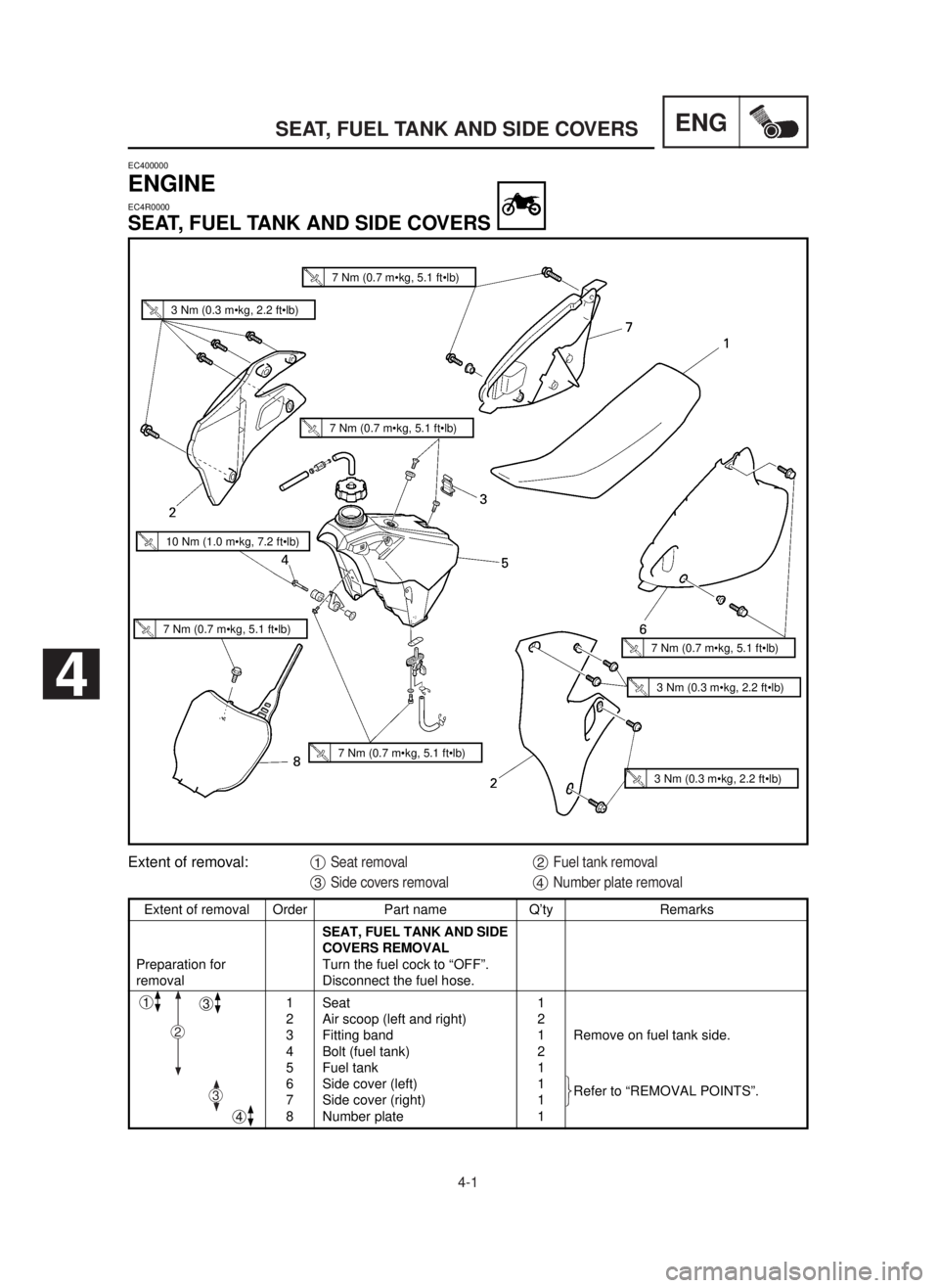
Extent of removal Order Part name Q’ty Remarks
SEAT, FUEL TANK AND SIDE
COVERS REMOVAL
Preparation for Turn the fuel cock to “OFF”.
removal Disconnect the fuel hose.
1 Seat 1
2 Air scoop (left and right) 2
3 Fitting band 1 Remove on fuel tank side.
4 Bolt (fuel tank) 2
5 Fuel tank 1
6 Side cover (left) 1
Refer to “REMOVAL POINTS”.
7 Side cover (right) 1
8 Number plate 1
1
4
3
Extent of removal:1Seat removal2Fuel tank removal
3Side covers removal4Number plate removal
2
ü
ý
þ ü
ý
þ3
4
3 Nm (0.3 m•kg, 2.2 ft•lb)
7 Nm (0.7 m•kg, 5.1 ft•lb)
7 Nm (0.7 m•kg, 5.1 ft•lb)
10 Nm (1.0 m•kg, 7.2 ft•lb)
7 Nm (0.7 m•kg, 5.1 ft•lb)
3 Nm (0.3 m•kg, 2.2 ft•lb)
3 Nm (0.3 m•kg, 2.2 ft•lb)
7 Nm (0.7 m•kg, 5.1 ft•lb)
7 Nm (0.7 m•kg, 5.1 ft•lb)
5MW-9-30-4A 7/3/00 4:58 PM Page 2
Page 214 of 578
4-2
ENGSEAT, FUEL TANK AND SIDE COVERS
EC4R3000
REMOVAL POINTS
EC413101
Side cover
1. Remove:
9Side cover (left and right) 1
cC
Be sure to remove the seat before remov-
ing the side cover. If you remove the side
cover with force without removing the seat,
the panel 2(on the inside) may contact
the air cleaner case and come off.
5MW-9-30-4A 7/3/00 4:58 PM Page 4
Page 216 of 578
ENG
4-3
EXHAUST PIPE AND SILENCER
EC4S0000
EXHAUST PIPE AND SILENCER
Extent of removal Order Part name Q’ty Remarks
EXHAUST PIPE AND
SILENCER REMOVAL
Preparation for Side cover (right) Refer to “SEAT, FUEL TANK AND
removal SIDE COVERS” section.
1 Bolt (silencer) 2
2 Silencer 1
3 Tension spring 2
4 Bolt (exhaust pipe) 2
5 Exhaust pipe 1
1
Extent of removal:1Silencer removal2Exhaust pipe removal
2
7 Nm (0.7 m•kg, 5.1 ft•lb)
12 Nm (1.2 m•kg, 8.7 ft•lb)
10 Nm (1.0 m•kg, 7.2 ft•lb)
25 Nm (2.5 m•kg, 18 ft•lb)
12 Nm (1.2 m•kg, 8.7 ft•lb)
12 Nm (1.2 m•kg, 8.7 ft•lb)
5MW-9-30-4A 7/3/00 4:58 PM Page 6
Page 218 of 578
ENG
4-4
RADIATOR
Extent of removal Order Part name Q’ty Remarks
RADIATOR REMOVAL
Preparation for Drain the coolant.
Refer to “COOLANT REPLACEMENT”
removal section in the CHAPTER 3.
Seat and fuel tank Refer to “SEAT, FUEL TANK AND
SIDE COVERS” section.
1 Panel 2 Refer to
“REMOVAL POINTS”.
2 Clamp (radiator hose 2, 3) 2 Only loosening.
3 Radiator hose 1 1
4 Radiator (left) 1
5 Radiator hose 4 1
6 Radiator (right) 1
7 Radiator hose 2 1
8 Radiator hose 3 1
9 Radiator breather hose 1
EC450001
RADIATOR
Extent of removal:1Radiator removal
1
1 Nm (0.1 m•kg, 0.7 ft•lb)
10 Nm (1.0 m•kg, 7.2 ft•lb)
1 Nm (0.1 m•kg, 0.7 ft•lb)
10 Nm (1.0 m•kg, 7.2 ft•lb)
5MW-9-30-4A 7/3/00 4:59 PM Page 8
Page 224 of 578
ENG
4-7
CARBURETOR AND REED VALVE
EC460000
CARBURETOR AND REED VALVE
Extent of removal Order Part name Q’ty Remarks
CARBURETOR AND
REED VALVE REMOVAL
Preparation for Fuel tank Refer to “SEAT, FUEL TANK AND
removal SIDE COVERS” section.
1 Solenoid valve lead 1 Disconnect the solenoid valve lead.
2 TPS (throttle position sensor) 1 Disconnect the TPS
lead (throttle position sensor) lead.
3 Clamp (carburetor joint) 2
Loosen the screws (carburetor joint).
4 Carburetor 1
5 Carburetor joint 1
6 Reed valve assembly 1
7 Stopper (reed valve) 2
8 Reed valve 2
1
Extent of removal:1Carburetor removal2Reed valve removal
2
10 Nm (1.0 m•kg, 7.2 ft•lb)
1 Nm (0.1 m•kg, 0.7 ft•lb)
5MW-9-30-4A 7/3/00 5:01 PM Page 14