Page 14 of 558

EC083000
MANUAL FORMAT
All of the procedures in this manual are organized in a sequential, step-by-step format. The informa-
tion has been complied to provide the mechanic with an easy to read, handy reference that contains
comprehensive explanations of all disassembly, repair, assembly, and inspection operations.
In this revised format, the condition of a faulty component will precede an arrow symbol and the
course of action required will follow the symbol, e.g.,
9Bearings
Pitting/DamageÕReplace.
EC084002
HOW TO READ DESCRIPTIONS
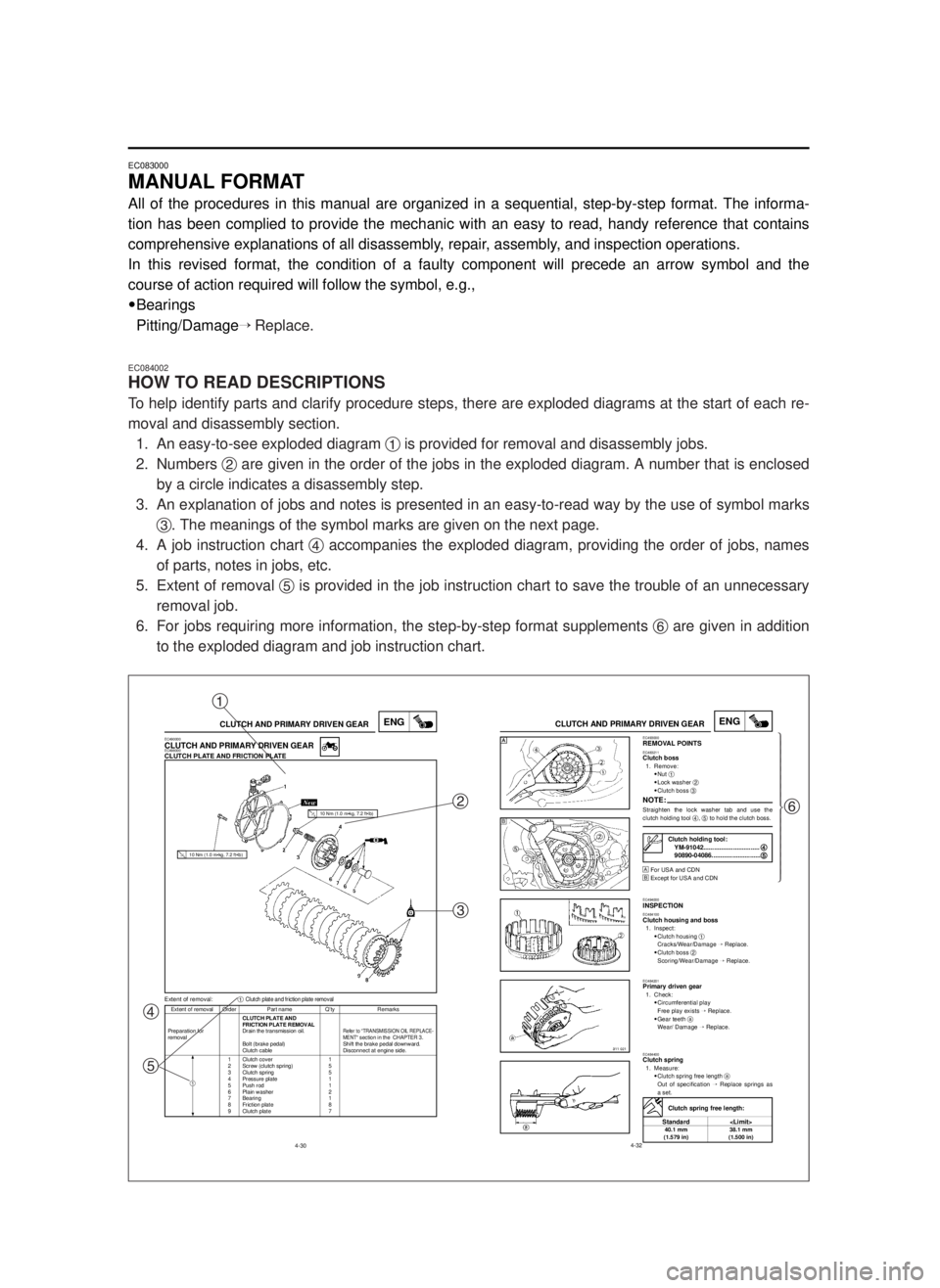
To help identify parts and clarify procedure steps, there are exploded diagrams at the start of each re-
moval and disassembly section.
1. An easy-to-see exploded diagram 1is provided for removal and disassembly jobs.
2. Numbers 2are given in the order of the jobs in the exploded diagram. A number that is enclosed
by a circle indicates a disassembly step.
3. An explanation of jobs and notes is presented in an easy-to-read way by the use of symbol marks
3. The meanings of the symbol marks are given on the next page.
4. A job instruction chart 4accompanies the exploded diagram, providing the order of jobs, names
of parts, notes in jobs, etc.
5. Extent of removal 5is provided in the job instruction chart to save the trouble of an unnecessary
removal job.
6. For jobs requiring more information, the step-by-step format supplements 6are given in addition
to the exploded diagram and job instruction chart.
4-30
ENGCLUTCH AND PRIMARY DRIVEN GEAR
Extent of removal Order Part name Q’ty Remarks
CLUTCH PLATE AND
FRICTION PLATE REMOVAL
Preparation for Drain the transmission oil.
Refer to “TRANSMISSION OIL REPLACE-removalMENT“ section in the CHAPTER 3.Bolt (brake pedal) Shift the brake pedal downward.
Clutch cable Disconnect at engine side.
1 Clutch cover 1
2 Screw (clutch spring) 5
3 Clutch spring 5
4 Pressure plate 1
5 Push rod 1
6 Plain washer 2
7 Bearing 1
8 Friction plate 8
9 Clutch plate 7
Extent of removal:1Clutch plate and friction plate removal
EC490000CLUTCH AND PRIMARY DRIVEN GEAREC498000CLUTCH PLATE AND FRICTION PLATE
1
10 Nm (1.0 m•kg, 7.2 ft•lb)
10 Nm (1.0 m•kg, 7.2 ft•lb)
4-32
ENGCLUTCH AND PRIMARY DRIVEN GEAREC493000REMOVAL POINTSEC483211Clutch boss1. Remove:
9Nut 1
9Lock washer 2
9Clutch boss 3
NOTE:Straighten the lock washer tab and use the
clutch holding tool 4, 5to hold the clutch boss.
Œ
For USA and CDN
º
Except for USA and CDN
EC494000INSPECTIONEC484100Clutch housing and boss1. Inspect:
9Clutch housing 1
Cracks/Wear/Damage Õ Replace.
9Clutch boss 2
Scoring/Wear/Damage ÕReplace.
EC484201Primary driven gear1. Check:
9Circumferential play
Free play exists ÕReplace.
9Gear teeth a
Wear/ Damage ÕReplace.
EC484400Clutch spring1. Measure:
9Clutch spring free length a
Out of specification ÕReplace springs as
a set.
Clutch holding tool:
YM-91042................................4 4
90890-04086............................5 5
Clutch spring free length:
Standard
40.1 mm 38.1 mm
(1.579 in) (1.500 in)
Œ
ºŒü
ï
ï
ï
ï
ï
ï
ï
ý
ï
ï
ï
ï
ï
ï
ï
þ
1
2
3
4
56
5MV-9-30-0 6/19/00 2:05 PM Page 12
Page 26 of 558
1-1
GEN
INFO
DESCRIPTION
EC100000
GENERAL INFORMATION
EC110000
DESCRIPTION
1Clutch lever
2”ENGINE STOP” button
3Front brake lever
4Throttle grip
5Radiator cap
6Fuel tank cap
7Kick starter
8Fuel tank
9Radiator
0Coolant drain bolt
qCheck bolt (Transmission oil level)
wRear brake pedal
eValve joint
rFuel cock
tAir cleaner
yDrive chain
uShift pedal
iStarter knob
oFront fork
NOTE:
9The machine you have purchased may differ
slightly from those shown in the following.
9Designs and specifications are subject to
change without notice.
1
5MV-9-30-1A 6/19/00 1:11 PM Page 2
Page 72 of 558

2-5
SPECMAINTENANCE SPECIFICATIONS
Part to be tightened Thread size Q'tyT ightening torqueNm m•kg ft•lb
Spark plug M14 ´1.25 1 20 2.0 14
Cylinder head (nut) M 8 ´1.25 5 28 2.8 20
(stud) M 8 ´1.25 5 13 1.3 9.4
Cylinder (nut) M 8 ´1.25 4 30 3.0 22
(stud) M10 ´1.25 4 13 1.3 9.4
Power valve:
Cover M 5 ´0.8 4 4 0.4 2.9
Link lever M 4 ´0.7 1 4 0.4 2.9
Holder (power valve) M 5 ´0.8 4 8 0.8 5.8
Push rod M 5 ´0.8 1 5 0.5 3.6
Thrust plate M 5 ´0.8 1 4 0.4 2.9
Governor fork M 4 ´0.7 2 5 0.5 3.6
Housing M 5 ´0.8 4 5 0.5 3.6
Impeller M 8 ´1.25 1 14 1.4 10
Water pump housing cover M 6 ´1.0 4 10 1.0 7.2
Coolant drain bolt M 6 ´1.0 1 10 1.0 7.2
Radiator hose clamp M 6 ´1.0 8 1 0.1 0.7
Air filter element M 6 ´1.0 1 2 0.2 1.4
Carburetor joint M 6 ´1.0 4 10 1.0 7.2
Air filter case M 6 ´1.0 2 4 0.4 2.9
Air filter joint M 5 ´0.8 5 1 0.1 0.7
Read valve M 3 ´0.5 6 1 0.1 0.7
Crankcase M 6 ´1.0 12 14 1.4 10
Crankcase cover (right) M 6 ´1.0 8 10 1.0 7.2
Crankcase cover (left) M 6 ´1.0 5 5 0.5 3.6
Chain cover M 6 ´1.0 2 5 0.5 3.6
Bearing plate cover M 6 ´1.0 3 10 1.0 7.2
Holder M 6 ´1.0 1 10 1.0 7.2
Oil check bolt M 6 ´1.0 1 10 1.0 7.2
Oil drain bolt M12 ´1.5 1 20 2.0 14
Kick starter M 6 ´1.0 1 10 1.0 7.2
Cluch cover M 6 ´1.0 6 10 1.0 7.2
Primary drive gear M10 ´1.25 1 55 5.5 40
Clutch boss M16 ´1.0 1 80 8.0 58
Clutch spring M 6 ´1.0 5 10 1.0 7.2
Push lever axle M 6 ´1.0 1 7 0.7 5.1
Drive sprocket M16 ´1.0 1 60 6.0 43
Shift pedal M 6 ´1.0 1 10 1.0 7.2
Bearing plate cover (shift cam) M 6 ´1.0 2 10 1.0 7.2
Shift guide M 6 ´1.0 2 10 1.0 7.2
Stopper lever M 6 ´1.0 1 10 1.0 7.2
Segment M 8 ´1.25 1 30 3.0 22
5MV-9-30-2A 6/19/00 1:15 PM Page 6
Page 138 of 558

3-5
INSP
ADJENGINE/COOLANT LEVEL INSPECTION/
COOLANT REPLACEMENT
EC350000
ENGINE
EC351011
COOLANT LEVEL INSPECTION
w
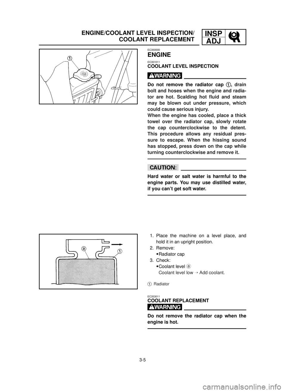
Do not remove the radiator cap 1 1
, drain
bolt and hoses when the engine and radia-
tor are hot. Scalding hot fluid and steam
may be blown out under pressure, which
could cause serious injury.
When the engine has cooled, place a thick
towel over the radiator cap, slowly rotate
the cap counterclockwise to the detent.
This procedure allows any residual pres-
sure to escape. When the hissing sound
has stopped, press down on the cap while
turning counterclockwise and remove it.
cC
Hard water or salt water is harmful to the
engine parts. You may use distilled water,
if you can’t get soft water.
1. Place the machine on a level place, and
hold it in an upright position.
2. Remove:
9Radiator cap
3. Check:
9Coolant level a
Coolant level low ÕAdd coolant.
1Radiator
EC353011
COOLANT REPLACEMENT
w
Do not remove the radiator cap when the
engine is hot.
5MV-9-30-3A 6/19/00 1:52 PM Page 18
Page 140 of 558
3-6
INSP
ADJ
COOLANT REPLACEMENT
cC
Take care so that coolant does not splash
on painted surfaces. If it splashes, wash it
away with water.
1. Place a container under the engine.
2. Remove:
9Coolant drain bolt 1
3. Remove:
9Radiator cap
Drain the coolant completely.
4. Clean:
9Cooling system
Thoroughly flush the cooling system with
clean tap water.
5. Install:
9Copper washer
9Coolant drain bolt
6. Fill:
9Radiator
9Engine
To specified level.
Recommended coolant:
High quality ethylene glycol
anti-freeze containing
anti-corrosion for
aluminum engine
Coolant 1 1
and water
(soft water) 2 2
mixing ratio:
50%/50%
Coolant capacity:
1.00 L (0.88 Imp qt, 1.06 US qt)
10 Nm (1.0 m•kg, 7.2 ft•lb)
5MV-9-30-3A 6/19/00 1:52 PM Page 20
Page 156 of 558
3-14
INSP
ADJ
PILOT AIR SCREW ADJUSTMENT
4. Remove:
9Oil drain bolt 1
9Oil filler cap 2
Drain the transmission oil.
5. Install:
9Aluminum washer
9Oil drain bolt 1
6. Fill:
9Transmission oil
7. Check:
9Oil leakage
8. Check:
9Transmission oil level
9. Install:
9Oil filler cap 2
EC35L002
PILOT AIR SCREW ADJUSTMENT
1. Adjust:
9Pilot air screw 1
Recommended oil:
Yamalube 4 (10W-30) or SAE
10W-30 type SE motor oil
Oil capacity
(periodic oil change):
0.65 L (0.57 Imp qt, 0.69 US qt)
Adjustment steps:
9Screw in the pilot air screw until it is
lightly seated.
9Back out by the specified number of
turns.
Pilot air screw:
1-1/4 turns out
*1-1/2 turns out
20 Nm (2.0 m•kg, 14 ft•lb)
*For EUROPE
5MV-9-30-3A 6/19/00 1:52 PM Page 36
Page 168 of 558
3-20
FRONT BRAKE PAD INSPECTION AND REPLACEMENT
INSP
ADJ
9Loosen the pad pin 2.
9Remove the brake hose holder 3and
caliper 4from the front fork.
9Remove the pad pin and brake pads 5.
9Connect the transparent hose 6to the
bleed screw 7and place the suitable con-
tainer under its end.
9Loosen the bleed screw and push the
caliper piston in.
cC
Do not reuse the drained brake fluid.
9Tighten the bleed screw.
9Install the brake pads 8and pad pin.
NOTE:
9Install the brake pads with their projections
ainto the caliper recesses b.
9Temporarily tighten the pad pin at this point.
9Install the brake hose holder 9and caliper
0and tighten the pad pin q.
NOTE:
Fit the brake hose holder cut c over the pro-
jection
don the front fork and clamp the
brake hose.
Bleed screw:
6 Nm (0.6 m•kg, 4.3 ft•b)
Bolt (caliper):
23 Nm (2.3 m•kg, 17 ft•lb)
Pad pin:
18 Nm (1.8 m•kg, 13 ft•lb)
5MV-9-30-3B 6/19/00 1:49 PM Page 4
Page 172 of 558

3-22
REAR BRAKE PAD INSPECTION AND REPLACEMENT
INSP
ADJ
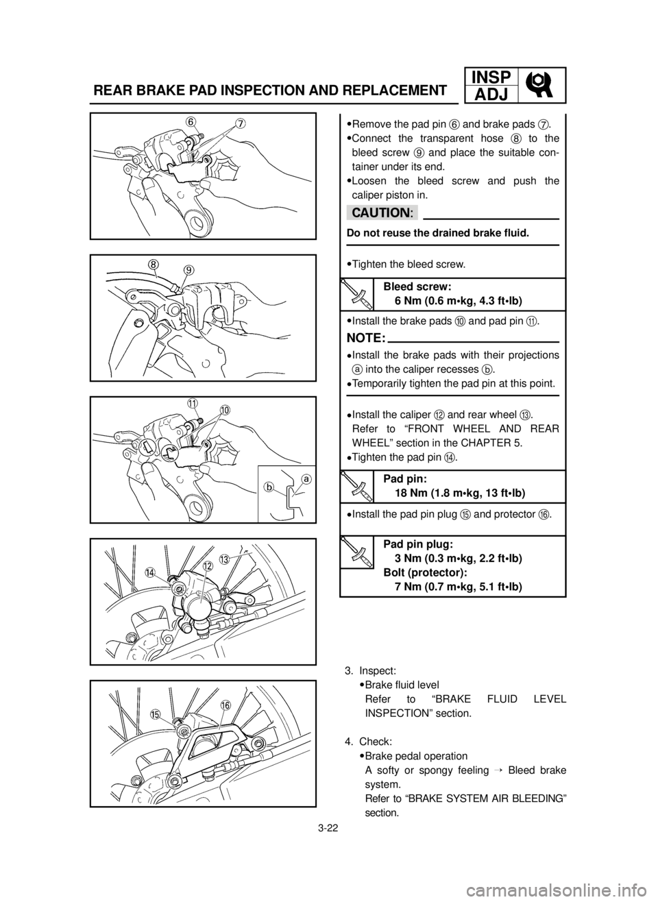
9Remove the pad pin 6and brake pads 7.
9Connect the transparent hose 8to the
bleed screw 9and place the suitable con-
tainer under its end.
9Loosen the bleed screw and push the
caliper piston in.
cC
Do not reuse the drained brake fluid.
9Tighten the bleed screw.
9Install the brake pads 0and pad pin q.
NOTE:
9Install the brake pads with their projections
ainto the caliper recesses b.
9Temporarily tighten the pad pin at this point.
9Install the caliper wand rear wheel e.
Refer to “FRONT WHEEL AND REAR
WHEEL” section in the CHAPTER 5.
9Tighten the pad pin r.
9Install the pad pin plug tand protector y.
Bleed screw:
6 Nm (0.6 m•kg, 4.3 ft•lb)
Pad pin:
18 Nm (1.8 m•kg, 13 ft•lb)
Pad pin plug:
3 Nm (0.3 m•kg, 2.2 ft•lb)
Bolt (protector):
7 Nm (0.7 m•kg, 5.1 ft•lb)
3. Inspect:
9Brake fluid level
Refer to “BRAKE FLUID LEVEL
INSPECTION” section.
4. Check:
9Brake pedal operation
A softy or spongy feeling ÕBleed brake
system.
Refer to “BRAKE SYSTEM AIR BLEEDING”
section.
5MV-9-30-3B 6/19/00 1:49 PM Page 8