Page 14 of 370

Yuki_Data:Yuki_data:Yuki:Yuki_1:ATV:HM00B067_YFM350X-60:YFM350TOC-E.frame
EL
EBU00015
CONTENTS
LOCATION OF THE WARNING AND
SPECIFICATION LABELS ....................... 1-1
SAFETY INFORMATION ........................ 2-1
DESCRIPTION AND MACHINE
IDENTIFICATION .................................... 3-1
Identification number records........... 3-3
Key identification number ................. 3-5
Vehicle identification number ........... 3-5
Model label ......................................... 3-7
CONTROL FUNCTIONS ......................... 4-1
Main switch ........................................ 4-1
Indicator lights.................................... 4-3
Handlebar switches............................ 4-5
Throttle lever ...................................... 4-9
Speed limiter .................................... 4-11
Clutch lever ....................................... 4-13
Front brake lever .............................. 4-13
Rear brake pedal .............................. 4-15
Parking brake .................................... 4-17
Shift pedal......................................... 4-21Drive select lever...............................4-21
Fuel tank cap .....................................4-23
Fuel cock ............................................4-23
Starter (choke) ...................................4-25
Seat ....................................................4-27
Front shock absorber adjustment....4-29
Rear shock absorber adjustment .....4-31
PRE-OPERATION CHECKS .....................5-1
Front and rear brakes .........................5-5
Fuel.......................................................5-9
Engine oil ...........................................5-13
Chain ..................................................5-15
Throttle lever .....................................5-17
Fittings and Fasteners ......................5-17
Lights .................................................5-17
Switches ............................................5-17
Battery................................................5-19
Tires ...................................................5-19
How to measure tire pressure .........5-23
Tire wear limit ...................................5-25
1234
5
Page 16 of 370

Yuki_Data:Yuki_data:Yuki:Yuki_1:ATV:HM00B067_YFM350X-60:YFM350TOC-E.frame
EL
Drive chain cleaning and
lubrication....................................... 8-61
Cable inspection and lubrication .... 8-63
Brake and shift pedal/brake and
clutch lever lubrication .................. 8-63
Upper and lower arm pivot
lubrication....................................... 8-65
Rear arm pivot lubrication............... 8-67
Wheel removal ................................. 8-69
Wheel installation ............................ 8-71
Battery ............................................... 8-73
Replenishing the battery fluid ......... 8-77
Fuse replacement ............................. 8-81
Replacing the headlight bulb .......... 8-83
Headlight beam adjustment ............ 8-89
Troubleshooting ............................... 8-91
Troubleshooting chart ..................... 8-93
CLEANING AND STORAGE................... 9-1
A. Cleaning ......................................... 9-1
B. Storage ........................................... 9-7SPECIFICATIONS ..................................10-1
HOW TO USE THE CONVERSION
TABLE ....................................................11-1
9
1011
Page 56 of 370
3-1
Yuki_Data:Yuki_data:Yuki:Yuki_1:ATV:HM00B067_YFM350X-60:YFM350-3.frame
EL
EBU00032
DESCRIPTION AND MACHINE
IDENTIFICATION
1. Seat
2. Drive select lever
3. Fuel tank cap
4. Main switch
5. Brake pedal
6. Headlight
7. Front wheel
8. Fuel cock9. Rear wheel
10. Shift pedal
11. Starter (choke)
12. Clutch lever
13. Parking brake
14. Front brake lever
15. Throttle lever
16. Handlebar switch
NOTE:
The machine you have purchased may differ
slightly from those shown in the figures of this
manual.
Page 100 of 370

5-1
Yuki_Data:Yuki_data:Yuki:Yuki_1:ATV:HM00B067_YFM350X-60:YFM350-5.frame
EL
EBU00113
PRE-OPERATION CHECKS
Before using this machine, check the following points:
ITEM ROUTINE PAGE
Brake
• Check operation, free play, fluid level and fluid leakage.
• Fill with DOT 4 (or DOT 3) brake fluid if necessary.5-5 ~ 5-7,
8-39 ~ 8-49
Clutch
• Check operation, condition and lever free play. 8-55
Parking brake
• Check operation, condition and cable slack. 8-51 ~ 8-53
Fuel
• Check fuel level.
• Fill with fuel if necessary.5-9 ~ 5-11
Engine oil
• Check oil level.
• Fill with oil if necessary.5-13 ~ 5-15,
8-15 ~ 8-23
Drive chain
• Check chain slack and condition.
• Adjust if necessary.5-15, 8-57 ~ 8-61
Throttle
• Check for proper throttle cable operation. 5-17, 8-37
Wheels and tires
• Check tire pressure, wear and damage.5-19 ~ 5-25,
8-69 ~ 8-71
Fittings and Fasteners
• Check all fittings and fasteners. 5-17
Lights
• Check for proper operation. 5-17, 8-83 ~ 8-89
Battery
• Check fluid level.
• Fill with distilled water if necessary.5-19, 8-73 ~ 8-79
Page 134 of 370
6-9
Yuki_Data:Yuki_data:Yuki:Yuki_1:ATV:HM00B067_YFM350X-60:YFM350-6.frame
EL
EBU00180
Starting a warm engine
To start a warm engine, refer to the “Starting a
cold engine” section. The starter (choke)
should not be used. The throttle should be
opened slightly.
EBU00538
Warming up
To get maximum engine life, always warm up
the engine before starting off. Never accelerate
hard with a cold engine! To see whether or not
the engine is warm, check if it responds to the
throttle normally with the starter (choke)
turned off.NOTE:
When the parking brake is used, engine speed
is limited to 2,300 r/min. Be sure the parking
brake is released before moving the throttle le-
ver. Otherwise, the engine will misfire, pre-
venting normal operation.
Page 136 of 370

6-11
Yuki_Data:Yuki_data:Yuki:Yuki_1:ATV:HM00B067_YFM350X-60:YFM350-6.frame
EL
EBU00188
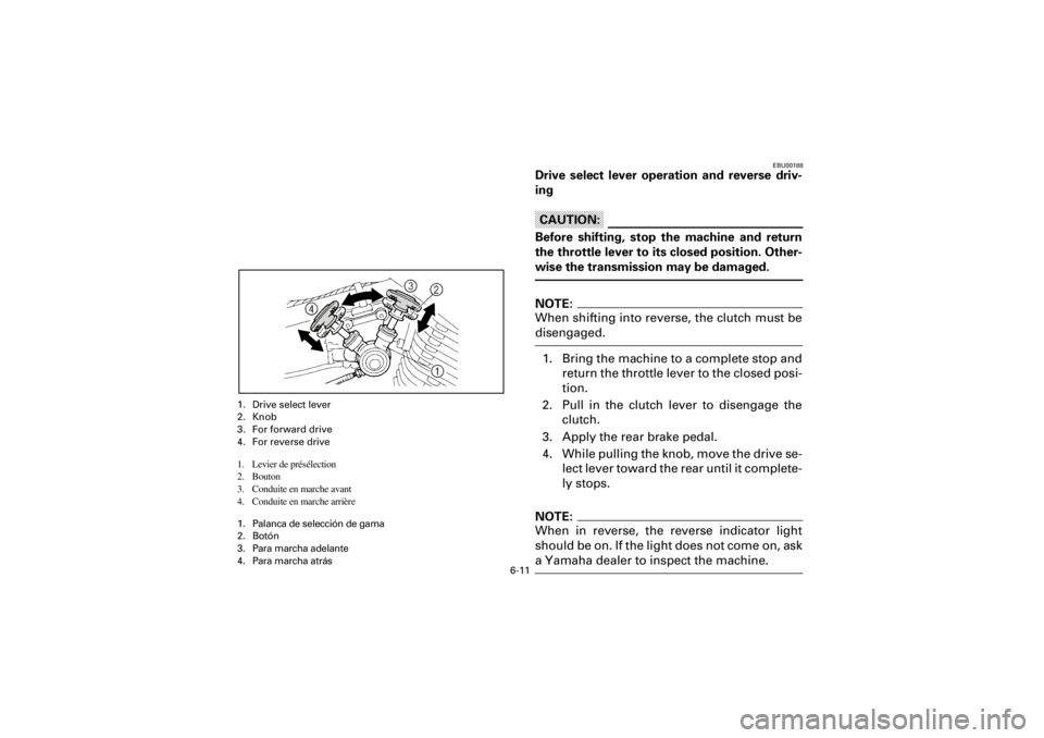
Drive select lever operation and reverse driv-
ing
CAUTION:
Before shifting, stop the machine and return
the throttle lever to its closed position. Other-
wise the transmission may be damaged.
NOTE:
When shifting into reverse, the clutch must be
disengaged.
1. Bring the machine to a complete stop and
return the throttle lever to the closed posi-
tion.
2. Pull in the clutch lever to disengage the
clutch.
3. Apply the rear brake pedal.
4. While pulling the knob, move the drive se-
lect lever toward the rear until it complete-
ly stops.
NOTE:
When in reverse, the reverse indicator light
should be on. If the light does not come on, ask
a Yamaha dealer to inspect the machine.
1. Drive select lever
2. Knob
3. For forward drive
4. For reverse drive
1. Levier de présélection
2. Bouton
3. Conduite en marche avant
4. Conduite en marche arrière
1. Palanca de selección de gama
2. Botón
3. Para marcha adelante
4. Para marcha atrás