Page 97 of 135
4-2
E
1. Put the watercraft on land in a horizontal
position.
2. Open the flushing hose connector cap 1,
and then inser t the garden hose adapter
2
into the flushing hose connector 3 and
turn it until it is securely connected.
3. Connect the garden hose adapter to a
water tap using a hose.
4. Start the engine, and then immediately
turn the water supply on until water flows
out continually from the cooling water
pilot outlet.
5. Run the engine at idling speed for about
3 minutes watching the engine condition.
If the engine stops while flushing, turn
the water supply off immediately and
repeat the above steps.
6. Turn the water supply off, and then force
the remaining water out from the cooling
passages by alternately squeezing, and
releasing the throttle lever for 10 to
15 seconds.
7. Stop the engine.
8. Remove the garden hose adapter and
secure the cap.
E_GU5-71-4.fm Page 2 Thursday, July 13, 2000 7:54 PM
Page 98 of 135

4-3
E
EJU00526a
Lubrication
WARNING
To reduce the risk of fire or explosion:
Never pour or spray gasoline, or any sub-
stance other than engine fogging oil
through the holes in the carburetor
silencer cover.
CAUTION:
●Be sure to replace the caps securely
after fogging the engine. Otherwise
water could enter the engine and
cause damage.
●Do not attempt to run the engine at full
throttle or for more than 15 seconds
while the watercraft is out of the water,
otherwise the engine may overheat
and/or seize.
1. Open the silencer caps 1 on the
silencer by turning them counterclock-
wise.
2. Start the engine with the watercraft in a
well-ventilated area.
3. With the engine running at a fast idle,
quickly spray as much fogging oil as pos-
sible through the holes in the silencer
cover. Keep spraying until the engine
stalls (or a maximum of 15 seconds).
4. Install the cap securely.
5. Remove the spark plugs and pour
approximately one tablespoon of engine
oil into each cylinder. Grease the spark
plug threads and install the spark plugs.
6. Crank the engine for 3 seconds.
7. Lubricate all cables such as the throttle,
choke, and steering cables.
8. Lubricate the areas of the watercraft
specified under Lubrication points on
page 4-15.
E_GU5-71-4.fm Page 3 Thursday, July 13, 2000 7:54 PM
Page 99 of 135

4-4
E
EJU00946
Fuel system
Draining the fuel system prevents buildup
of varnishes and other harmful deposits that
result when gasoline sits for a prolonged
period of time.
WARNING@Gasoline is highly flammable and explo-
sive. A fire or explosion can cause
severe injury or death. Shut the engine
off. Refuel in well-ventilated areas away
from flames or sparks. Do not smoke.
Avoid spilling gasoline. Wipe up spilled
gasoline immediately.
@
To drain the fuel system:
1. Place the fuel cock knob in the “OFF”
position.
2. Drain the fuel tank using a siphon.
EJU00530
Battery
When the watercraft is not to be used for
a month or more, remove the battery and
store it in a cool, dark place. Clean the bat-
tery casing using fresh water. Clean the bat-
tery terminals. Apply dielectric grease or
petroleum jelly to the battery terminals and
to all exposed battery leads.
If the battery is to be stored for a longer
period, check the specific gravity of the elec-
trolyte at least once a month and charge the
battery if necessary.
Specific gravity: 1.28 at 20 °C (68 °F)
E_GU5-71-4.fm Page 4 Thursday, July 13, 2000 7:54 PM
Page 100 of 135
4-5
E
EJU00531
Cleaning the watercraft
Clean the watercraft before storing for a
long period.
1. Wash down the hull, handlebars, and
drive unit with fresh water.
2. Rinse the engine and bilge area with
fresh water. Drain off all water and wipe
up remaining moisture with clean, dry
rags.
3. Spray the engine’s exterior with a rust
inhibitor and lubricant.
4. Wax the hull with a non-abrasive wax.
5. Wipe all vinyl and rubber components,
such as the seat and engine compart-
ment seals, with a vinyl protectant.
E_GU5-71-4.fm Page 5 Thursday, July 13, 2000 7:54 PM
Page 101 of 135

4-6
E
EJU00535a
Maintenance and
adjustments
Periodic inspection, adjustment and lubri-
cation will keep your watercraft in the safest
and most efficient condition possible. Safety
is an obligation of the watercraft owner. The
most important points of watercraft inspec-
tion, adjustment and lubrication are
explained on the following pages.
See your Yamaha dealer for genuine
Yamaha replacement parts and optional
accessories designed for your watercraft.
Remember that failures that are the result
of the installation of parts or accessories
which are not qualitatively equivalent to gen-
uine Yamaha parts are not covered by the
limited warranty.
WARNING
●Be sure to turn off the engine when
you perform maintenance unless oth-
erwise specified, otherwise an acci-
dent or injury could result from
unexpected operation, moving parts,
or electric shock. If the owner is not
familiar with watercraft servicing, this
work should be done by a Yamaha
dealer. Improperly serviced compo-
nents could fail or stop operating cor-
rectly, which could result in an
accident.
●Modifications to this watercraft not
approved by Yamaha may cause loss
of performance or excessive noise, or
render it unsafe for use. Consult a
Yamaha dealer before attempting any
changes.
E_GU5-71-4.fm Page 6 Thursday, July 13, 2000 7:54 PM
Page 102 of 135
4-7
E
Owner’s/Operator’s Manual
and tool kit
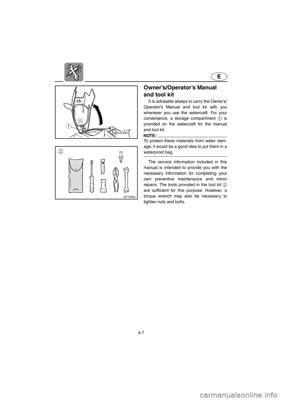
It is advisable always to carry the Owner’s/
Operator’s Manual and tool kit with you
whenever you use the watercraft. For your
convenience, a storage compartment 1 is
provided on the watercraft for the manual
and tool kit.
NOTE:
To protect these materials from water dam-
age, it would be a good idea to put them in a
waterproof bag.
The service information included in this
manual is intended to provide you with the
necessary information for completing your
own preventive maintenance and minor
repairs. The tools provided in the tool kit 2
are sufficient for this purpose. However, a
torque wrench may also be necessary to
tighten nuts and bolts.
E_GU5-71-4.fm Page 7 Thursday, July 13, 2000 7:54 PM
Page 103 of 135

4-8
E
EJU00536
Periodic maintenance chart
The following chart gives general guidelines for periodic maintenance. However, depend-
ing on your operating conditions maintenance may need to be performed more frequently.
(
●) This mark indicates maintenance that you may do yourself.
(
❍) This mark indicates work to be done by a Yamaha dealer.
*1: Grease capacity: 33.0–35.0 cm3 (1.11–1.18 oz)
*2: Grease capacity: 6.0–8.0 cm3 (0.20–0.27 oz)
*3: Grease capacity: 8.0 cm3 (0.27 oz)
*4: Grease capacity: 2.0 cm3 (0.07 oz)
MAINTENANCE INTERVAL INITIALTHEREAFTER
EVERYPA G E
10
hours50
hours100
hours100
hours200
hours
ITEM
3
months6
months6
months12
months
Spark plug Inspect, clean, adjust●●●●
4-14
Lubrication points Lubricate●●
4-15
Intermediate housing Lubricate❍
*1●
*2●
*2 4-18
Starter motor idle gear Lubricate❍
*3●
*4●
*4 4-18
Fuel system Inspect❍❍
4-9
Fuel filter Check, replace❍❍
4-10
Fuel tank Clean❍
4-10
Oil injection system Inspect, clean❍❍
—
Carburetor setting Inspect, adjust❍❍❍
4-21
Trolling speed Adjust●●
4-21
Carburetor throttle shaft Inspect❍❍
—
Cooling water passages Flush
●
(after
ever y
use)4-1
Bilge strainer Clean●●●
—
Impeller Inspect●●●
5-4
Steering cable Inspect●●
5-4
Steering master Inspect❍❍❍
—
QSTS mechanism Inspect●●
4-13
Shift cable and mechanism Inspect, adjust●●
4-17
Throttle cable Inspect, adjust●●
4-16
Choke cable Inspect, adjust●●
4-18
Stern drain plugs Inspect, replace●
3-7
Battery Inspect
●(inspect
fluid level
before
ever y
use)
4-19
Rubber coupling Inspect❍
—
Nuts and bolts Tighten❍❍❍
—
E_GU5-71-4.fm Page 8 Thursday, July 13, 2000 7:54 PM
Page 104 of 135
4-9
E
EJU00537
Inspecting the fuel system
WARNING
Gasoline and its vapors are highly flam-
mable and explosive.
Check the fuel system for leaks, cracks,
or malfunctions. If any problem is found, do
the necessary repair or replacement as
required. If repair is necessary, consult a
Yamaha dealer.
Check:
●Carburetor for leakage.
●Fuel pump for malfunction or leakage.
●Fuel tank for water or dirt.
●Fuel tank for damage, cracks or leakage.
●Fuel hose joint for leakage.
●Fuel hose for cracks or other damage.
●Fuel filter for leakage.
●Fuel cock for leakage.
●Air vent check valve for leakage.
●Fuel tank filler cap for damage.
WARNING
Failure to check for and repair any fuel
leakage may result in fire or explosion.
E_GU5-71-4.fm Page 9 Thursday, July 13, 2000 7:54 PM