Page 14 of 106
DESCRIPTION
12
3
4
5
6
7
8
9
2-2
9.Passenger seat
10.Rider seat(page 3-11)
11.Air flow louver(page 6-22)
12.Headlight (page 6-34)
13.Radiator14.Battery(page 6-31)
15.Fuse box(page 6-33)
16.Coolant reservoir cap (page 6-19)
17.Coolant level check window (page 6-19)
18.Engine oil filler cap(page 6-15)
10
11
12
13 16 17
1815, 14
9
Right view
5GM-9-E1(No ABS) 9/27/00 2:18 PM Page 13
Page 75 of 106

6-31
PERIODIC MAINTENANCE AND MINOR REPAIR
1
2
3
4
56
7
8
9
EAU00796
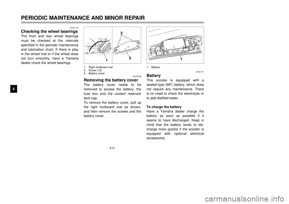
Removing the battery coverThe battery cover needs to be
removed to access the battery, the
fuse box and the coolant reservoir
tank cap.
To remove the battery cover, pull up
the right footboard mat as shown,
and then remove the screws and the
battery cover.
2
3
1
1.Right footboard mat
2.Screw (´2)
3.Battery cover
1
1.Battery
EAU01271
BatteryThis scooter is equipped with a
sealed-type (MF) battery, which does
not require any maintenance. There
is no need to check the electrolyte or
to add distilled water.
To charge the battery
Have a Yamaha dealer charge the
battery as soon as possible if it
seems to have discharged. Keep in
mind that the battery tends to dis-
charge more quickly if the scooter is
equipped with optional electrical
accessories.
EAU01144
Checking the wheel bearingsThe front and rear wheel bearings
must be checked at the intervals
specified in the periodic maintenance
and lubrication chart. If there is play
in the wheel hub or if the wheel does
not turn smoothly, have a Yamaha
dealer check the wheel bearings.
5GM-9-E1(No ABS) 9/27/00 2:18 PM Page 74
Page 77 of 106

2.Remove the blown fuse, and
then install a new fuse of the
specified amperage.
EC000103
cCDo not use a fuse of a higher
amperage rating than recommend-
ed to avoid causing extensive
damage to the electrical system
and possibly a fire.3.Turn the key to ÒONÓ and turn on
the electrical circuit in question to
check if the device operates.
6-33
PERIODIC MAINTENANCE AND MINOR REPAIR
1
2
3
4
56
7
8
94.If the fuse immediately blows
again, have a Yamaha dealer
check the electrical system.
Specified fuses:
Main fuse:30 A
Clock fuse:10 A
Radiator fan fuse:4 A
Ignition fuse:7.5 A
Headlight fuse:15 A
Signaling system fuse:15 A
4
5
67
1
32
78
EAU03622
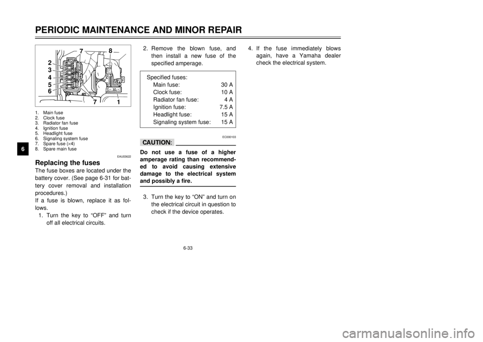
Replacing the fusesThe fuse boxes are located under the
battery cover. (See page 6-31 for bat-
tery cover removal and installation
procedures.)
If a fuse is blown, replace it as fol-
lows.
1.Turn the key to ÒOFFÓ and turn
off all electrical circuits.1.Main fuse
2.Clock fuse
3.Radiator fan fuse
4.Ignition fuse
5.Headlight fuse
6.Signaling system fuse
7.Spare fuse (´4)
8.Spare main fuse
5GM-9-E1(No ABS) 9/27/00 2:18 PM Page 76