Page 623 of 4323
 3. Reference pressure
Saturated
4. Reference pressure difference between
first and second±5.25 mmHg (0.7 kPa)
7. Leak check±")
± DIAGNOSTICSENGINE
DI±421
615 Author�: Date�:
2005 SEQUOIA (RM1146U) 3. Reference pressure
Saturated
4. Reference pressure difference between
first and second±5.25 mmHg (0.7 kPa)
7. Leak check±
Next sequence is run if following condition
set±
FTP when vacuum introduction was com-
plete±Second reference pressure
8. Atmospheric pressure±
Monitor is complete if following±
Atmospheric pressure difference between
sequence 1 and 8±2.25 mmHg (0.3 kPa)
TYPICAL MALFUNCTION THRESHOLDS
Detection CriteriaThreshold
Vent valve stuck open:
Following valuers are when atmospheric pressure is 760
mmHg (100 kPa)±
One of the following conditions setCondition 1, 2, 3, 4 or 5
1. FTP when 4 sec. after reference pressure measurement
began±7.5 mmHg (±1 kPa) or more
2. Reference pressure±36.38 mmHg (±4.85 kPa) or less
3. Reference pressure±7.93 mmHg (±1.057 kPa) or more
4. Reference pressureNot saturated
5. Reference pressure difference between first and secondMore than 5.25 mmHg (0.7 kPa)
Vent valve stuck closed:
FTP change for 10 sec. after vent valve openedLess than 2.25 mmHg (0.3 kPa)
MONITOR RESULT (MODE 06 DATA)
Refer to page DI±26 for detailed information on Monitor Result.
INSPECTION PROCEDURE
Refer to the EVAP Inspection Procedure (see page DI±460).
Page 625 of 4323

MONITOR STRATEGY
P2430Air flow/pressure sensor circuit range check
(Fluctuating)
P2431Air flow/pressure sensor circuit rationa")
± DIAGNOSTICSENGINE
DI±423
617 Author�: Date�:
2005 SEQUOIA (RM1146U)
MONITOR STRATEGY
P2430Air flow/pressure sensor circuit range check
(Fluctuating)
P2431Air flow/pressure sensor circuit rationality
Related DTCsP2432Air flow/Pressure sensor circuit range check
(Low voltage)
P2433Air flow/pressure sensor circuit range check
(High voltage)
Required sensors/componentsPressure sensor
Frequency of operationContinuous
DurationP2430, P2432, P2433: 0.5 sec.
P2431: 5 sec.
MIL operationP2430, P2432, P2433: Immediate
P2431: 2 driving cycles
Sequence of operationNone
TYPICAL ENABLING CONDITIONS
ItSpecificationItemMinimumMaximum
The monitor will run whenever these
DTCs are not presentSee page DI±18
StarterOFF
Time after starter turned from ON to OFF2 sec.±
Battery voltage8 V±
Ignition switchON
TYPICAL MALFUNCTION THRESHOLDS
Detection CriteriaThreshold
P2430:
Air pressure sensor voltageLess than 0.1 V, or more than 4.8 V
P2432:
Air pressure sensor voltageLess than 0.1 V
P2433:
Air pressure sensor voltageMore than 4.8 V
P2431:
Air pressureLess than 338 mmHg (45 kPa), or more than 1013 mmHg (135 kPa)
Page 626 of 4323
A23557
ECM A42
Air Pressure Sensor
VC
AIP
E2
E8 E8 E8
2832 23
VC
AIP
E2EB4
EB4
EB4G±B G±B
B±Y
B±Y
G±W
G±W6 5 15 V
B17412
E8
E2AIP VC
B17439
Wire Harness Side:
Pressure Sensor Connector
A42
E2
AIP VC
DI±424
± DIAGNOSTICSENGINE
618 Author�: Date�:
2005 SEQUOIA (RM1146U)
WIRING DIAGRAM
INSPECTION PROCEDURE
1 Check for open and short in harness and connector between pressure sensor
and ECM (See page IN±35).
PREPARATION:
(a) Remove the intake manifold (see page EM±36).
(b) Disconnect the A42 pressure sensor connector.
(c) Disconnect the E8 ECM connector.
CHECK:
Measure the resistance between the wire harness side connec-
tors.
OK:
Standard:
Tester ConnectionSpecified Condition
VC (A42±1) ± VC (E8±23)
AIP (A42±2) ± AIP (E8±32)
E2 (A42±3) ± AIP (E8±28)
Below 1 W
VC (A42±1) or VC (E8±23) ±
Body ground
AIP (A42±2) or AIP (E8±32) ±
Body ground
10 kW or higher
NG Repair or replace harness and connector.
OK
Page 627 of 4323
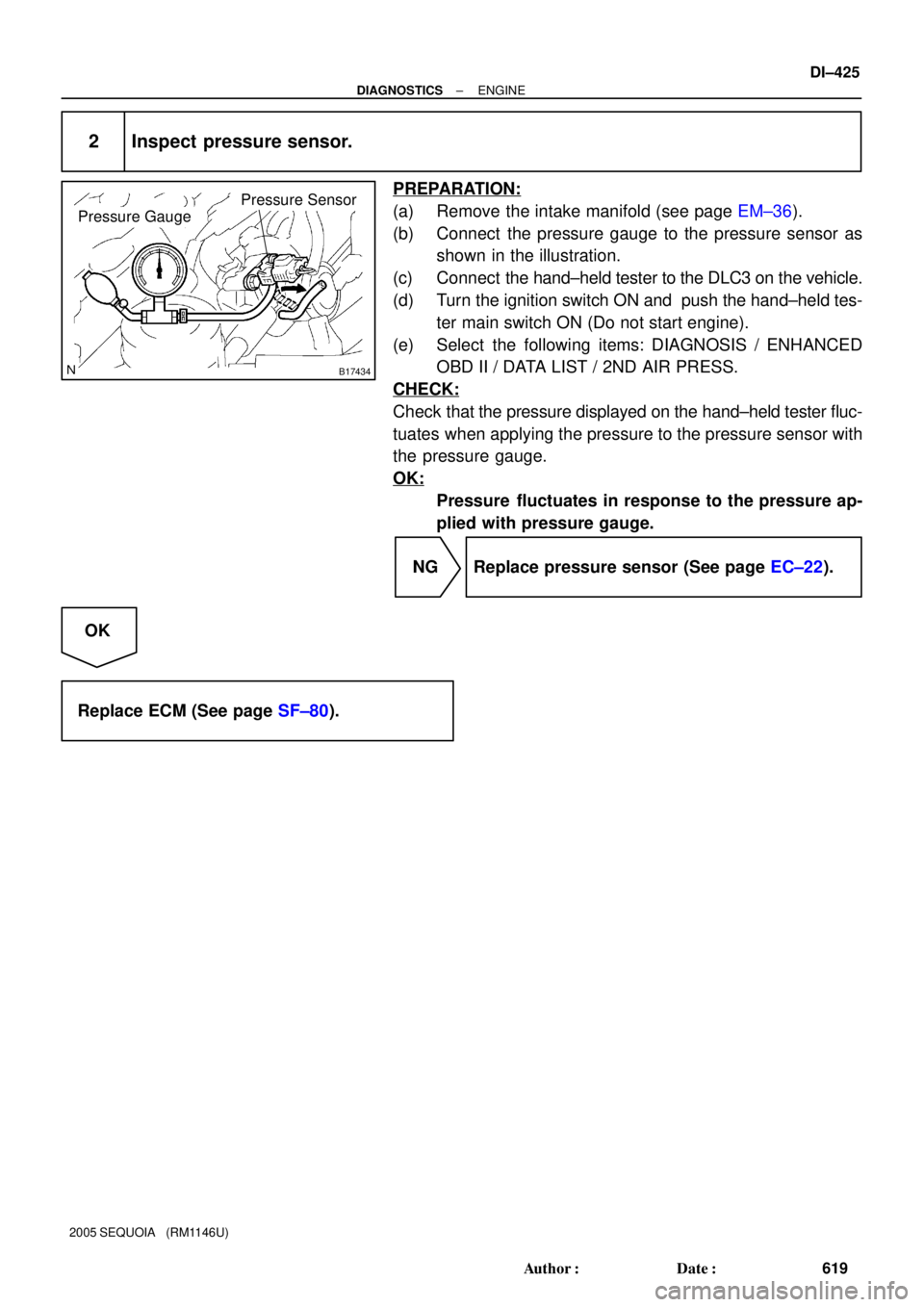
B17434
Pressure Gauge
Pressure Sensor
± DIAGNOSTICSENGINE
DI±425
619 Author�: Date�:
2005 SEQUOIA (RM1146U)
2 Inspect pressure sensor.
PREPARATION:
(a) Remove the intake manifold (see page EM±36).
(b) Connect the pressure gauge to the pressure sensor as
shown in the illustration.
(c) Connect the hand±held tester to the DLC3 on the vehicle.
(d) Turn the ignition switch ON and push the hand±held tes-
ter main switch ON (Do not start engine).
(e) Select the following items: DIAGNOSIS / ENHANCED
OBD II / DATA LIST / 2ND AIR PRESS.
CHECK:
Check that the pressure displayed on the hand±held tester fluc-
tuates when applying the pressure to the pressure sensor with
the pressure gauge.
OK:
Pressure fluctuates in response to the pressure ap-
plied with pressure gauge.
NG Replace pressure sensor (See page EC±22).
OK
Replace ECM (See page SF±80).
Page 631 of 4323

MONITOR RESULT
Refer to page DI±26 for detailed information.
The test value and test limit information are described as shown")
± DIAGNOSTICSENGINE
DI±429
623 Author�: Date�:
2005 SEQUOIA (RM1146U)
MONITOR RESULT
Refer to page DI±26 for detailed information.
The test value and test limit information are described as shown in the following table. Check the monitor
result and test values after performing the monitor drive pattern (refer to ºConfirmation Monitorº).
�MID (Monitor Identification Data) is assigned to each emissions±related component.
�TID (Test Identification Data) is assigned to each test value.
�Scaling is used to calculate the test value indicated on generic OBD ll scan tools.
Secondary air injection (AIR) system
MIDTIDScalingDescription of Test ValueMinimum Test LimitMaximum Test Limit
$71$E1Multiply by 0.01
(g/s)Test value of AIR amount insufficientMinimum test limitMaximum test limit
$71$E2Multiply by 0.01
(kPa)Test value of AIR pump stuck ONMinimum test limitMaximum test limit
$71$E3Multiply by 0.01
(kPa)Test value of AIR pump stuck OFFMinimum test limitMaximum test limit
$71$E4Multiply by 0.01
(kPa)Test value of AIR control valve ONMinimum test limitMaximum test limit
$71$E5Multiply by 0.01
(kPa)Test value of AIR control valve OFFMinimum test limitMaximum test limit
$71$E6Multiply by 0.01
(kPa)Test value of AIR pressure change for
AIR valveMinimum test limitMaximum test limit
$71$E7Multiply by 0.01
(kPa)Test value of AIR pressure change for
AIR VSV bank 1Minimum test limitMaximum test limit
$71$E8Multiply by 0.01
(kPa)Test value of AIR pressure change for
AIR VSV bank 2Minimum test limitMaximum test limit
$71$E9Multiply by 0.01
(kPa)Test value of AIR pressure pulsation for
AIR VSV when AIR pressure is lowMinimum test limitMaximum test limit
WIRING DIAGRAM
Refer to DTC P0412 on page DI±234.
Page 632 of 4323
DI±430
± DIAGNOSTICSENGINE
624 Author�: Date�:
2005 SEQUOIA (RM1146U)
INSPECTION PROCEDURE
HINT:
To check the pressure condition in the secondary air passage, the hand±held tester is available.
1 Is the DTC P2444 and/or P2445 being output?
PREPARATION:
(a) Connect the hand±held tester to the DLC3.
(b) Turn the ignition switch ON and push the hand±held tester main switch ON.
(c) Select the following items: DIAGNOSIS/ENHANCED OBD II/DTC INFO/CURRENT CODES.
CHECK:
Read the DTCs.
RESULT:
Display (DTC output)Proceed to
P2445A
P2444B
P2444 and P2445B
ºP2444 and P2445º and other DTCsC
HINT:
If any other codes besides P2444 or P2445 is output, perform troubleshooting for those DTCs first.
B Go to step 7.
C Go to DTC chart (See page DI±58).
A
Page 633 of 4323

A16555
AIR INJ CHECK
AIR PUMP............................ON
EASV ............................OPEN
ASV1. .............................OPEN
ASV2...............................OPEN
A/F BANK1.......................19.05
A/F BANK2.........................14.5
PRESSURE....................17 kPa
PULSATION..............25.39 kPa
AI STATUS...........................OK
Remaining Time 05 sec.
Press [EXIT] to quit
± DIAGNOSTICSENGINE
DI±431
625 Author�: Date�:
2005 SEQUOIA (RM1146U)
2 Check air injection system pressure.
PREPARATION:
(a) Start the engine and warm it up.
(b) Turn the ignition switch to OFF.
(c) Connect the hand±held tester to the DLC3.
(d) Turn the ignition switch to ON and push the hand±held
tester main switch ON.
(e) Start the engine.
CHECK:
(a) Select the following menu items: DIAGNOSIS/EN-
HANCED OBD II/SYSTEM CHECK/ AIR INJ CHECK/
MANUAL OPERATION/OPERATION 1 and 2
HINT:
OPERATION 1: AP:OFF, EASV:CLOSE, ASV1:CLOSE,
ASV2:CLOSE
OPERATION 2: AP:ON, EASV:OPEN, ASV1:OPEN,
ASV2:OPEN
(b) Check that the PRESSURE on the hand±held tester.
NOTICE:
This test only allows technicians to operate the AI system
for 5 seconds. Furthermore, the test can be performed 4
times a trip. If the test is repeated, intervals of at least 30
seconds are required between tests.
While the AI system operation using the hand±held tester
is prohibited, the tester displays the prohibition (WAIT or
ERROR). If the ERROR (AI STATUS NG) is displayed on the
tester, stop the engine for 10 minutes and then try again..
OK:
Tester operationPRESSURE
Operation 1Less then 2.5 kPa
Operation 25 to 8 kPa or more
NG Go to step 4.
OK
Page 634 of 4323

3 Check whether DTC output recurs.
PREPARATION:
(a) Start the engine and warm it up.
(b) Turn the ignition s")
B17435Vacuum Hose
DI±432
± DIAGNOSTICSENGINE
626 Author�: Date�:
2005 SEQUOIA (RM1146U)
3 Check whether DTC output recurs.
PREPARATION:
(a) Start the engine and warm it up.
(b) Turn the ignition switch OFF.
(c) Connect a hand±held tester to the DLC3.
(d) Turn the ignition switch to ON and turn the tester ON.
(e) Clear the DTCs (see page DI±43).
(f) Start the engine.
CHECK:
(a) Perform SYSTEM CHECK to operate the air injection system.
Select the following menu items: DIAGNOSIS/ENHANCED OBD II/SYSTEM CHECK/AIR INJ
CHECK/AUTOMATIC OPERATION
(b) After operating the secondary air injection system, confirm the pending codes for the secondary air
injection system by selecting the following menu items: DIAGNOSIS / ENHANCED OBD II / DTC INFO
/ PENDING CODES.
(c) Read DTCs and check that no DTC is set.
OK:
DTC P2444 or P2445 for the secondary air injection system is not output.
NG Go to step 4.
OK
Check for intermittent problems
(See page DI±11).
4 Check vacuum hose.
CHECK:
(a) Remove the intake manifold (see page EM±36).
(b) Check the vacuum hose connection between the pres-
sure sensor and air switching valve.
OK:
The vacuum hose is securely connected.
CHECK:
(a) Check the vacuum hose for blockage or damage.
OK:
The vacuum hose has no blockage or damage.
NG Repair or replace vacuum hose.
OK