Page 572 of 1943
PP±58
± PREPARATIONAIR CONDITIONING
11 9 Author�: Date�:
2001 PRIUS (RM778U)
09870±00015A/C Quick Joint Puller No.1Suction tube
09870±00025A/C Quick Joint Puller No.2Liquid tube
Page 573 of 1943
PP3AE±01
± PREPARATIONAIR CONDITIONING
PP±59
2001 PRIUS (RM778U)
RECOMMENDED TOOLS
09040±00011Hexagon Wrench Set .
(09043±20050)Socket Hexagon Wrench 5.Expansion valve
5.0 mm (0.20 in.)
(09043±20100)Socket Hexagon Wrench 10.Radiator & condenser module
10 mm (0.39 in.)
09082±00040TOYOTA Electrical Tester.
09216±00021Belt Tension Gauge .
09905±00013Snap Ring Pliers .
Page 574 of 1943
PP3AF±02
PP±60
± PREPARATIONAIR CONDITIONING
2001 PRIUS (RM778U)
EQUIPMENT
Voltmeter
Ammeter
Ohmmeter
Test lead
ThermometerSensor, ECT switch
Torque wrench
Dial indicatorMagnetic clutch
Plastic hammerMagnetic clutch
Page 575 of 1943
PP3AG±01
± PREPARATIONAIR CONDITIONING
PP±61
2001 PRIUS (RM778U)
LUBRICANT
ItemCapacityClassification
Compressor oil±ND±OIL 8 or equivalent
When replacing condenser40 cc (1.4 fl.oz.)
When replacing evaporator40 cc (1.4 fl.oz.)
When replacing compressor120 cc (4.1 fl.oz.)
Page 769 of 1943

FI7012A11860
P±G A/C Control Assembly
A8 E10522
ACTECM
± DIAGNOSTICSENGINE
DI±171
2001 PRIUS (RM778U)
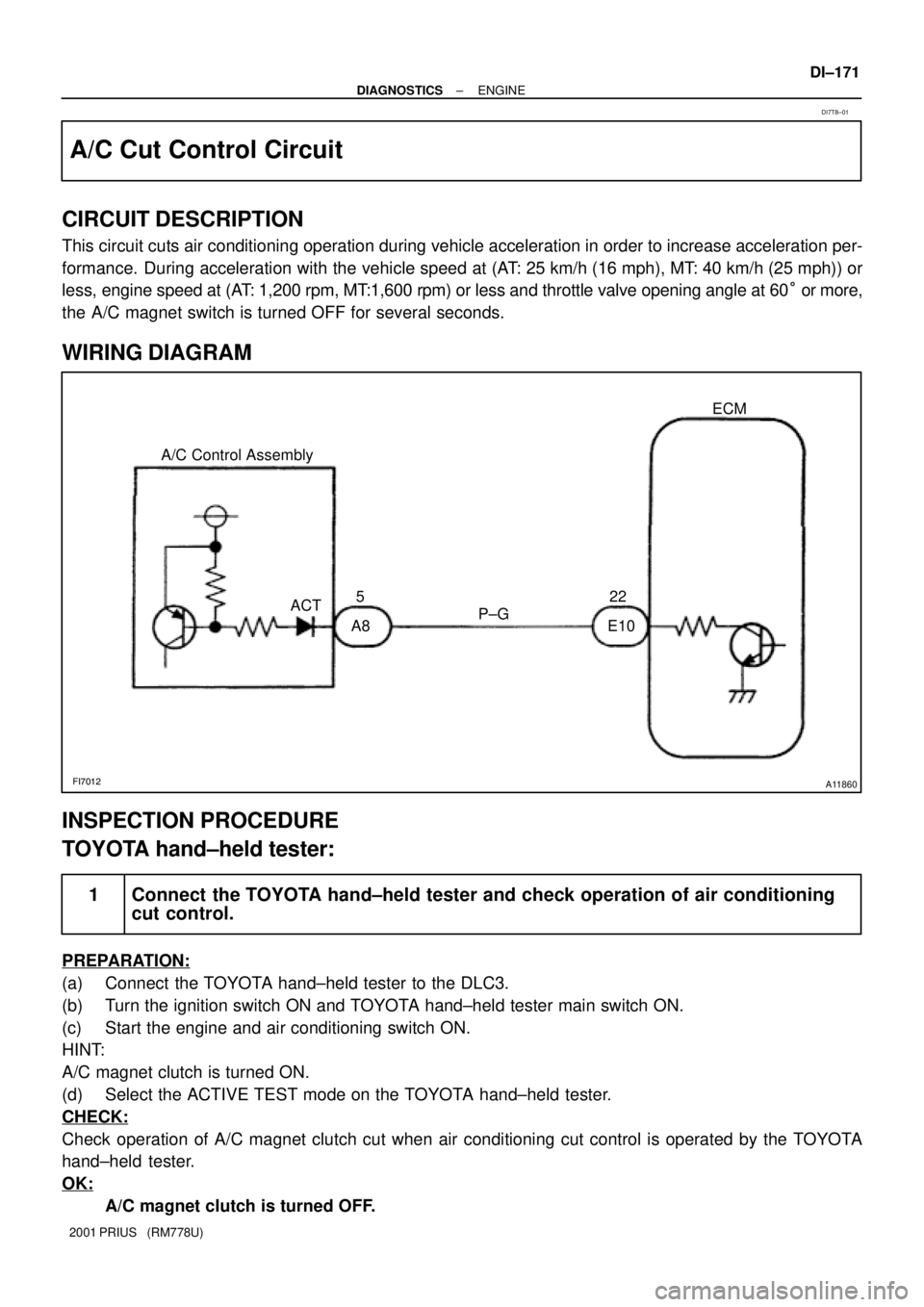
A/C Cut Control Circuit
CIRCUIT DESCRIPTION
This circuit cuts air conditioning operation during vehicle acceleration in order to increase acceleration per-
formance. During acceleration with the vehicle speed at (AT: 25 km/h (16 mph), MT: 40 km/h (25 mph)) or
less, engine speed at (AT: 1,200 rpm, MT:1,600 rpm) or less and throttle valve opening angle at 60° or more,
the A/C magnet switch is turned OFF for several seconds.
WIRING DIAGRAM
INSPECTION PROCEDURE
TOYOTA hand±held tester:
1 Connect the TOYOTA hand±held tester and check operation of air conditioning
cut control.
PREPARATION:
(a) Connect the TOYOTA hand±held tester to the DLC3.
(b) Turn the ignition switch ON and TOYOTA hand±held tester main switch ON.
(c) Start the engine and air conditioning switch ON.
HINT:
A/C magnet clutch is turned ON.
(d) Select the ACTIVE TEST mode on the TOYOTA hand±held tester.
CHECK:
Check operation of A/C magnet clutch cut when air conditioning cut control is operated by the TOYOTA
hand±held tester.
OK:
A/C magnet clutch is turned OFF.
DI7T8±01
Page 1378 of 1943

DI7S1±01
AT0716
0.5 Seconds
0.5 Seconds ON
OFF
With in 5 sec. after turning the ignition on,
press the A/C switch 3 times and turn the
blower switch from OFF to AUTO.
Indicator check (See step 3)
Actuator check (See step 5)
Cancel check mode and can start
A/C control.If both A/C switch and blower
switch are not operated.
: Indicates a blower switch operation
DTC check (See step 4)
Actuator check (See step 5)
After indicators blink 4 times
Auto
Except Auto
Except AutoAuto
± DIAGNOSTICSAIR CONDITIONING SYSTEM
DI±871
2001 PRIUS (RM778U)
PRE±CHECK
1. WARNING FOR A/C COMPRESSOR LOCK
If compressor lock occurs during A/C operation, the A/C switch
indicator on the A/C control assembly starts blinking.
When this occurs, check for compressor lock (DTC 22) using
diagnosis trouble code check then proceed to inspect the circuit
or the component.
Compressor lock sensor circuit. " (See page DI±891)
2. LIST OF OPERATION METHODS
By operating each of the A/C control switches as shown in the diagram below, it is possible to enter the diag-
nosis check mode.
Page 1379 of 1943

I18151
Blower Switch
A/C Switch
I00339
Blinking Pattern
4 times
1 sec.
1 sec.
ON
OFF
ON
OFF
ON
OFF1 sec.
0.5 sec.
0.5
sec.1.5 sec 2.5 sec. 1.5 sec. No Malfunction
Malfunction Detected
u "
4.5 sec.
Repeat DI±872
± DIAGNOSTICSAIR CONDITIONING SYSTEM
2001 PRIUS (RM778U)
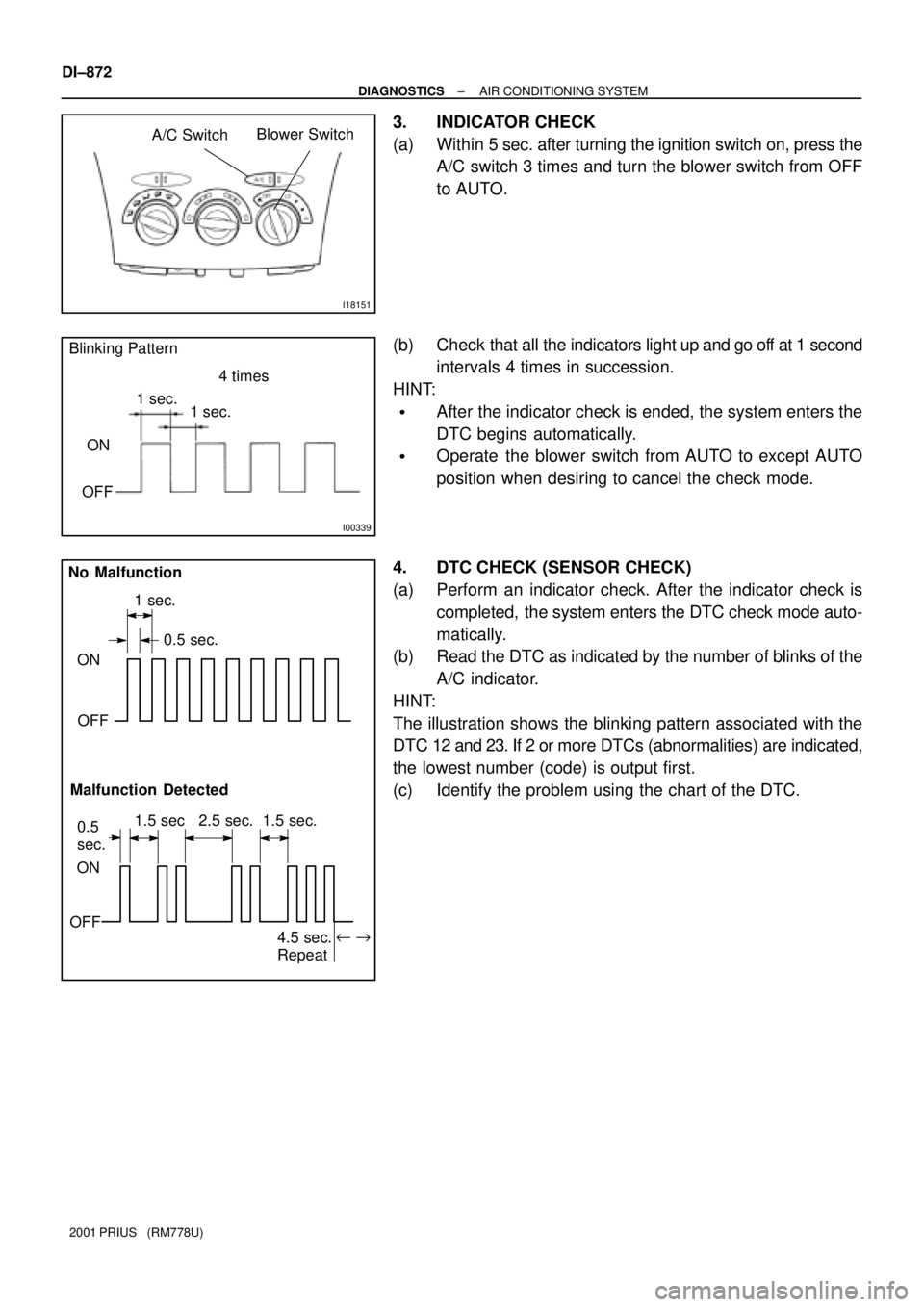
3. INDICATOR CHECK
(a) Within 5 sec. after turning the ignition switch on, press the
A/C switch 3 times and turn the blower switch from OFF
to AUTO.
(b) Check that all the indicators light up and go off at 1 second
intervals 4 times in succession.
HINT:
�After the indicator check is ended, the system enters the
DTC begins automatically.
�Operate the blower switch from AUTO to except AUTO
position when desiring to cancel the check mode.
4. DTC CHECK (SENSOR CHECK)
(a) Perform an indicator check. After the indicator check is
completed, the system enters the DTC check mode auto-
matically.
(b) Read the DTC as indicated by the number of blinks of the
A/C indicator.
HINT:
The illustration shows the blinking pattern associated with the
DTC 12 and 23. If 2 or more DTCs (abnormalities) are indicated,
the lowest number (code) is output first.
(c) Identify the problem using the chart of the DTC.
Page 1380 of 1943
I18151
Blower Switch
Max. Cool e
20.5 (66)
Step
No.Temp. setting
°C (°F)Blower Level Air Mix Damper
R/F
(102.0 %)ON Air Inlet
DamperAir Outlet
DamperCompressor
1
2
3
4
521.0 e 23.5
(67 e72)
24.0 e 26.0
(73 e77)
26.5 e 29.0
(78 e83)
29.5 (84)
eMax. Warm4
" "
17
31
"
"
50 %
(Cool/Warm)±10 %
(Cool)
100 %
(Warm)REC
(±1 %)
R/F
(82.0 %)
FRS
(110.0 %)
FRS
(110.0 %) DEF
(110 %)FOOT
(50 %)
F/D
(90 %) B/L
(15 %) FACE
(±10 %)
OFF
" "
"
± DIAGNOSTICSAIR CONDITIONING SYSTEM
DI±873
2001 PRIUS (RM778U)
5. ACTUATOR CHECK
(a) Actuator check mode is started at the same time with DTC
check mode.
(b) Check visually on by hand that the air flow, amount of
damper operating and operation of the compressor
changes according to the set temperature of the A/C con-
trol panel, as shown in the chart.
HINT:
To cancel the check mode, turn blower switch from AUTO to ex-
cept AUTO.