Page 506 of 1943
± INTRODUCTIONTERMS
IN±53
2001 PRIUS (RM778U) TCM
Transmission Control ModuleTransmission ECU, ECT ECU
TPThrottle PositionThrottle Position
TRTransmission Range±
TVVThermal Vacuum ValveBimetallic Vacuum Switching Valve (BVSV)
Thermostatic Vacuum Switching Valve (TVSV)
TWCThree±Way Catalytic Converter
Three±Way Catalytic (TWC)
Manifold Converter
CC
RO
TWC+OCThree±Way + Oxidation Catalytic ConverterCCR + CCo
VA FVolume Air FlowAir Flow Meter
VRVoltage RegulatorVoltage Regulator
VSSVehicle Speed SensorVehicle Speed Sensor
WOTWide Open ThrottleFull Throttle
WU±OCWarm Up Oxidation Catalytic Converter±
WU±TWCWarm Up Three±Way Catalytic Converter±
3GRThird Gear±
4GRFourth Gear±
Page 537 of 1943
PP3AM±01
± PREPARATIONHYBRID TRANSAXLE
PP±23
84 Author�: Date�:
2001 PRIUS (RM778U)
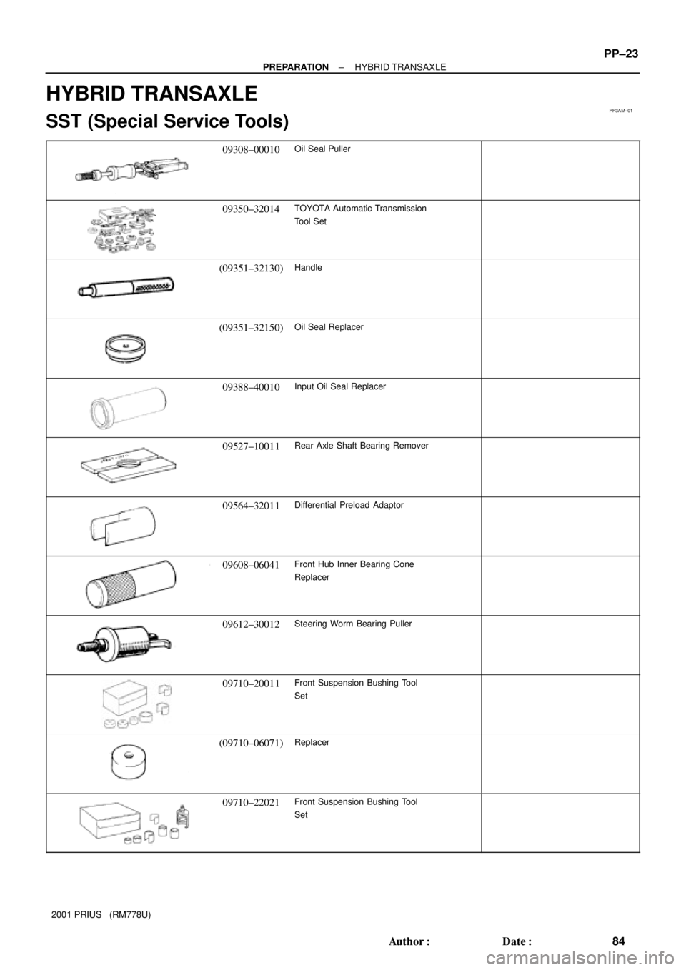
HYBRID TRANSAXLE
SST (Special Service Tools)
09308±00010Oil Seal Puller
09350±32014TOYOTA Automatic Transmission
Tool Set
(09351±32130)Handle
(09351±32150)Oil Seal Replacer
09388±40010Input Oil Seal Replacer
09527±10011Rear Axle Shaft Bearing Remover
09564±32011Differential Preload Adaptor
09608±06041Front Hub Inner Bearing Cone
Replacer
09612±30012Steering Worm Bearing Puller
09710±20011Front Suspension Bushing Tool
Set
(09710±06071)Replacer
09710±22021Front Suspension Bushing Tool
Set
Page 539 of 1943
± PREPARATIONHYBRID TRANSAXLE
PP±25
86 Author�: Date�:
2001 PRIUS (RM778U)
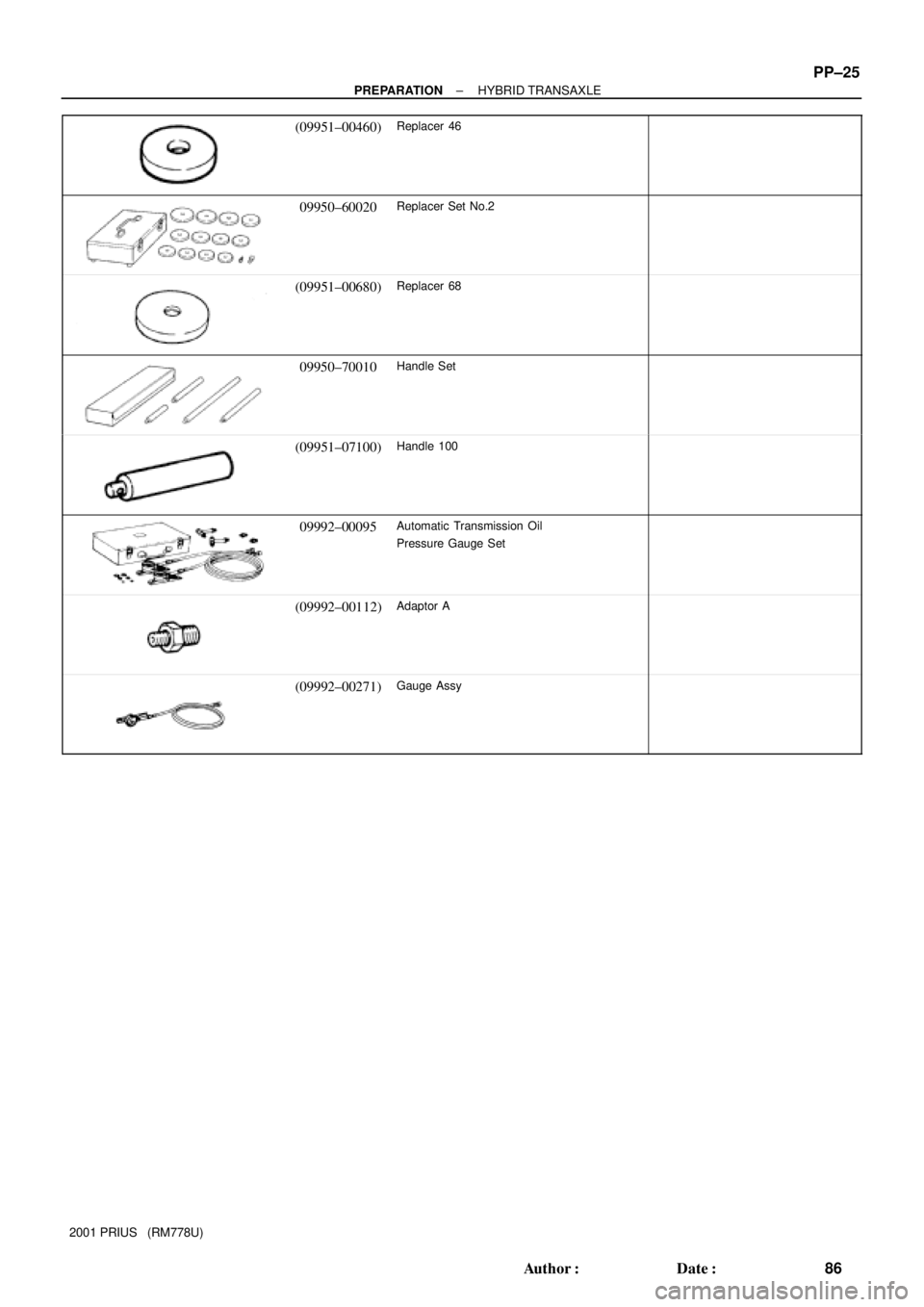
(09951±00460)Replacer 46
09950±60020Replacer Set No.2
(09951±00680)Replacer 68
09950±70010Handle Set
(09951±07100)Handle 100
09992±00095Automatic Transmission Oil
Pressure Gauge Set
(09992±00112)Adaptor A
(09992±00271)Gauge Assy
Page 613 of 1943

(b) Check the DLC3.
The vehicles ECM uses ISO 9141±2 for communication.
The terminal arrangement of DLC3 complies with SAE
J1962 and ma")
N09214
FI2547
± DIAGNOSTICSENGINE
DI±5
2001 PRIUS (RM778U)
(b) Check the DLC3.
The vehicle's ECM uses ISO 9141±2 for communication.
The terminal arrangement of DLC3 complies with SAE
J1962 and matches the ISO 9141±2 format.
Terminal No.Connection / Voltage or ResistanceCondition
7Bus � Line / Pulse generationDuring transmission
4Chassis Ground / e Body Ground 1 W or lessAlways
5Signal Ground / e Body Ground 1 W or lessAlways
16Battery Positive / e Body Ground 9 ± 14 VAlways
HINT:
If your display shows ºUNABLE TO CONNECT TO VEHICLEº
when you have connected the cable of the TOYOTA hand±held
tester or OBDII scan tool to DLC3, turned the ignition switch ON
and operated the scan tool, there is a problem on the vehicle
side or tool side.
�If communication is normal when the tool is connected to
another vehicle, inspect DLC3 on the original vehicle.
�If communication is still not possible when the tool is con-
nected to another vehicle, the problem is probably in the
tool itself, so consult the Service Department listed in the
tool's instruction manual.
2. INSPECT DIAGNOSIS (Normal Mode)
(a) Check the MIL
(1) The MIL comes on when the ignition switch is turned
ON and the engine is not running.
HINT:
If the MIL does not light up, troubleshoot the combination meter
(See page BE±42).
(2) When the engine started, the MIL should go off. If
the lamp remains on, the diagnosis system has de-
tected a malfunction or abnormality in the system.
(b) Check the DTC.
NOTICE:
�If there is no DTC in the normal mode, check the 1st
trip DTC using Continuous Test Result function
(Mode 7 for SAE J1979) or the TOYOTA hand±held
tester or OBDII scan tool.
Page 615 of 1943

3. INSPECT DIAGNOSIS (Check Mode)
TOYOTA hand±held tester only:
Compared to the normal mode, the check mode has an i")
FI3605
ON
OFFFlashing
0.13 Second
± DIAGNOSTICSENGINE
DI±7
2001 PRIUS (RM778U)
3. INSPECT DIAGNOSIS (Check Mode)
TOYOTA hand±held tester only:
Compared to the normal mode, the check mode has an in-
creased sensitivity to detect malfunctions.
Furthermore, the same diagnostic items which are detected in
the normal mode can also be detected in the check mode.
(a) Check the DTC
(1) Initial conditions:
�Battery positive voltage 11 V or more.
�Throttle valve fully closed.
�Transmission in ºPº or ºNº position.
�A/C switched OFF.
(2) Turn the ignition switch OFF.
(3) Prepare the TOYOTA hand±held tester.
(4) Connect the TOYOTA hand±held tester to DLC3
under the instrument panel lower pad.
(5) Turn the ignition switch ON and switch the TOYOTA
hand±held tester ON.
(6) Switch the TOYOTA hand±held tester normal mode
to check mode. (Check that the MIL flashes.)
NOTICE:
If the TOYOTA hand±held tester switches the ECM from the
normal mode to the check mode or vice±versa, or if the
ignition switch is turned from ON to ACC or LOCK during
check mode, the DTCs and freezed frame data will be
erased.
(7) Switch the engine. (The MIL goes out after the en-
gine start.)
(8) Simulate the conditions of the malfunction de-
scribed by the customer.
NOTICE:
Leave the ignition switch ON until you have checked the
DTC, etc.
(9) After simulating the malfunction conditions, use the
TOYOTA hand±held tester diagnosis selector to
check the DTCs and freezed frame data, etc.
HINT:
Take care not to turn the ignition switch OFF. Turning the ignition
switch OFF switches the diagnosis system from check mode to
normal mode. so all DTCs, etc. are erased.
(10) After checking the DTC, inspect the applicable cir-
cuit.
Page 617 of 1943
EM9891
± DIAGNOSTICSENGINE
DI±9
2001 PRIUS (RM778U)
3 Check air filter.
PREPARATION:
Remove the air filter.
CHECK:
Visual check that the air filter is not dirty or excessive oily.
HINT:
If necessary, clean the air filter with compressed air. First blow
from inside thoroughly, then blow from outside of the air filter.
NG Repair or replace.
OK
4 Check engine idle speed.
PREPARATION:
(a) Warm up engine to normal operating temperature.
(b) Switch off all accessories.
(c) Switch off A/C.
(d) Shift transmission into P position.
(e) Connect the TOYOTA hand±held tester or OBDII scan tool to DLC3 on the vehicle.
(f) Transit to inspection mode.
CHECK:
Use CURRENT DATA to check the idle speed.
OK:
Idle speed: 950 ± 1,050 rpm
NG Proceed to problem symptoms table on page
DI±22.
OK
Page 618 of 1943

5 Check ignition timing.
PREPARATION:
(a) Warm up engine to normal operating temperature.
(b) Shift transmission into")
A04438A13924A14466
TC
CG
A14060
DI±10
± DIAGNOSTICSENGINE
2001 PRIUS (RM778U)
5 Check ignition timing.
PREPARATION:
(a) Warm up engine to normal operating temperature.
(b) Shift transmission into P position.
(c) Keep the engine speed at idle.
(d) Using SST, connect terminals TE1 and E1 of DLC1.
SST 09843±18020
(e) Using a timing light, connect the tester to the ignition coil
connector wire (See page EM±11).
(f) Transit to inspection mode.
CHECK:
Check ignition timing.
OK:
Ignition timing: 7 ± 15° BTDC at idle
NG Proceed to page IG±1 and continue to trouble-
shoot.
OK
Proceed to problem symptoms table on page
DI±22.
6 Check fuel pressure.
PREPARATION:
(a) Be sure that enough fuel is in the tank.
(b) Connect the TOYOTA hand±held tester to the DLC3.
(c) Turn the ignition switch ON and push the TOYOTA hand±
held tester main switch ON.
(d) Use the ACTIVE TEST mode to operate the fuel pump.
(e) Please refer to the TOYOTA hand±held tester operator's
manual for further details.
(f) If you have no TOYOTA hand±held tester, connect the
positive (+) and negative (±) leads from the battery to the
fuel pump connector (See page SF±6).
CHECK:
Check for fuel pressure in the fuel inlet hose when it is pinched
off.
HINT:
At this time, you will hear a fuel flowing noise.
Page 775 of 1943

�Freeze frame data:
As the freeze frame data records the driving condi-
tion wh")
A04550
DLC3
912 3 4 56 78
16 15 14 13 12 11 10
DI±178
± DIAGNOSTICSHYBRID VEHICLE CONTROL SYSTEM
2001 PRIUS (RM778U)
�Freeze frame data:
As the freeze frame data records the driving condi-
tion when a malfunction is detected, when trouble-
shooting, it is useful for determining whether the ve-
hicle was running, braked, stopped or reversed.
(b) Check the DLC3.
The HV control ECU conforms to ISO 14230 for commu-
nication.
The terminal arrangement of the DLC3 complies with
SAEJ1962 and matches the ISO 14230 format.
Terminal No.Connection/Voltage or ResistanceCondition
7Bus � Line/Pulse generationDuring transmission
4Chassis Ground e Body Ground/1 W or lessAlways
5Signal Ground e Body Ground/1 W or lessAlways
16Battery Positive e Body Ground/10 ± 15 VAlways
HINT:
If your display shows UNABLE TO CONNECT TO VEHICLE
when you have connected the cable of the TOYOTA hand±held
tester to the DLC3, turned the motor switch ON and operated
the tester, there is a problem in the vehicle or tool.
�If communication is normal when the tool is connected to
another vehicle, inspect the DLC3 on the original vehicle.
�If communication is still not possible when the tool is con-
nected to another vehicle, the problem is probably in the
tool itself, so consult the Service Department.
3. INSPECT DIAGNOSIS
(a) Check the auxiliary battery.
(1) Measure the voltage of the auxiliary battery.
Voltage: 10 ± 15 V
(2) Inspect the auxiliary battery, fuses, fusible links, wir-
ing harness, connectors and ground.
 TCM
Transmission Control ModuleTransmission ECU, ECT ECU
TPThrottle PositionThrottle Position
TRTransmission Range±
TVVThermal Vacuum ValveBimetallic")

3 Check air filter.
PREPARATION:
Remove the air filter.
CHECK:
Visual check that the air filter is not dirty or excessive oily.
HINT:
If necessa")