Page 1156 of 1943

H01016AB0119
H08394H08269
Airbag
Sensor
Assembly P/T Squib (LH)
PL+
(±) (+) ON
DI±594
± DIAGNOSTICSSUPPLEMENTAL RESTRAINT SYSTEM
2001 PRIUS (RM778U)
DTC B0138/72 Short in P/T Squib (LH) Circuit (to B+)
CIRCUIT DESCRIPTION
The P/T squib (LH) circuit consists of the airbag sensor assembly and seat belt pretensioner (LH).
It causes the SRS to deploy when the SRS deployment conditions are satisfied.
For details of the function of each component, see OPERATION on page RS±2.
DTC B0138/72 is recorded when a B+ short is detected in the P/T squib (LH) circuit.
DTC No.DTC Detecting ConditionTrouble Area
B0138/72
�Short circuit in seat belt pretensioner (LH) wire harness
(to B+)
�P/T squib (LH) malfunction
�Airbag sensor assembly malfunction�Seat belt pretensioner (LH)
�Airbag sensor assembly
�Wire harness
WIRING DIAGRAM
See page DI±579.
INSPECTION PROCEDURE
1 Prepare for inspection (See step 1 on page DI±629).
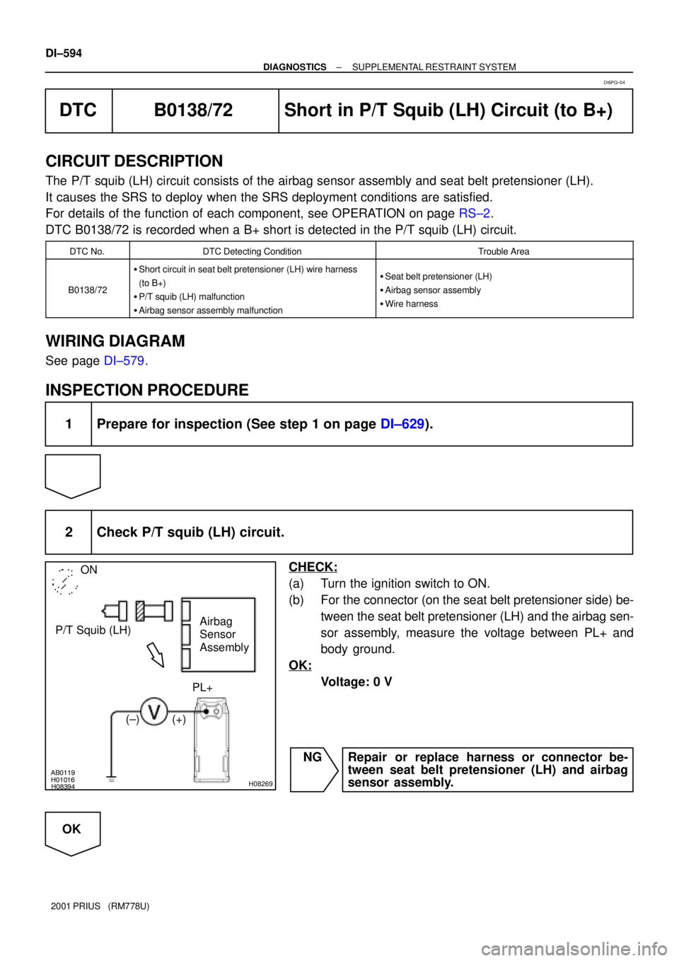
2 Check P/T squib (LH) circuit.
CHECK:
(a) Turn the ignition switch to ON.
(b) For the connector (on the seat belt pretensioner side) be-
tween the seat belt pretensioner (LH) and the airbag sen-
sor assembly, measure the voltage between PL+ and
body ground.
OK:
Voltage: 0 V
NG Repair or replace harness or connector be-
tween seat belt pretensioner (LH) and airbag
sensor assembly.
OK
DI6PQ±04
Page 1159 of 1943

AB0119H01298H01299
(±) (+)ONAirbag Sensor Assembly
IG1
IG2
± DIAGNOSTICSSUPPLEMENTAL RESTRAINT SYSTEM
DI±597
2001 PRIUS (RM778U)
DTC B1100/31 Airbag Sensor Assembly Malfunction
CIRCUIT DESCRIPTION
The airbag sensor assembly consists of a airbag sensor, safing sensor, drive circuit, diagnosis circuit and
ignition control, etc.
It receives signals from the airbag sensor, judges whether or not the SRS must be activated, and detects
diagnosis system malfunction.
DTC B1100/31 is recorded when occurrence of a malfunction in the airbag sensor assembly is detected.
DTC No.DTC Detecting ConditionTrouble Area
B1100/31�Airbag sensor assembly malfunction�Airbag sensor assembly
INSPECTION PROCEDURE
HINT:
When a malfunction code other than code B1100/31 is displayed at the same time, first repair the malfunction
indicated by the malfunction code other than code B1100/31.
1 Prepare for inspection (See step 1 on page DI±629).
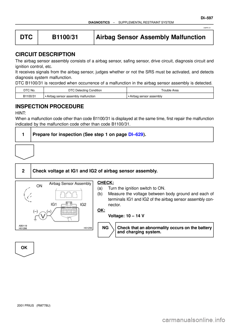
2 Check voltage at IG1 and IG2 of airbag sensor assembly.
CHECK:
(a) Turn the ignition switch to ON.
(b) Measure the voltage between body ground and each of
terminals IG1 and IG2 of the airbag sensor assembly con-
nector.
OK:
Voltage: 10 ± 14 V
NG Check that an abnormality occurs on the battery
and charging system.
OK
DI6PR±01
Page 1161 of 1943
± DIAGNOSTICSSUPPLEMENTAL RESTRAINT SYSTEM
DI±599
2001 PRIUS (RM778U)
DTC B1135/24 Harf Connection in Airbag Sensor Assembly
Connector
CIRCUIT DESCRIPTION
The airbag sensor assembly detects partial connection of connector.
For details of the function of each component, see OPERATION on page RS±2.
DTC B1135/24 is recorded when the airbag sensor assembly detects an open in the electrical connection
chech mechanism of the airbag sensor connector or in the airbag sensor circuit.
DTC No.DTC Detecting ConditionTrouble Area
B1135/24
�Malfunction of electrical connection check mechanism of
airbag sensor assembly connector
�Airbag sensor assembly malfunction�Electrical connection check mechanism
�Airbag sensor assembly
INSPECTION PROCEDURE
1 Are connector of center airbag sensor assembly properly connected?
NG Connect connectors.
OK
2 Prepare for inspection (See step 1 on page DI±629).
DI7IA±06
Page 1164 of 1943
H01450
Side Airbag Sensor Assembly (RH)
Airbag Sensor Assembly
GR
LG
L±Y
P ESR
FSR
SSR+
VUPR4
3
2
1A1910
7
9
12ESR
SSR±
SSR+
VUPR A19
A19
A19 DI±602
± DIAGNOSTICSSUPPLEMENTAL RESTRAINT SYSTEM
2001 PRIUS (RM778U)
DTC B1140/32 Side Airbag Sensor Assembly (RH)
Malfunction
CIRCUIT DESCRIPTION
The side airbag sensor assembly (RH) consists of the safing sensor, diagnosis circuit and lateral decelera-
tion sensor, etc.
It receives signals from the lateral deceleration sensor, judges whether or not the SRS must be activated,
and detects diagnosis system malfunction.
DTC B1140/32 is recorded when occurrence of a malfunction in the side airbag sensor assembly (RH) is
detected.
DTC No.DTC Detecting ConditionTrouble Area
B1140/32�Side airbag sensor assembly (RH) malfunction
�Side airbag sensor assembly (RH)
�Wire harness
�Airbag sensor assembly
WIRING DIAGRAM
DI6PS±03
Page 1172 of 1943
H01450
Side Airbag Sensor Assembly (LH)
Airbag Sensor Assembly
LG±B
L±W
P±L ESL
FSL
SSL+
VUPL4
3
2
1A179
12
10
7 GR±L
ESL
SSL±
SSL+
VUPL A17
A17
A17 DI±610
± DIAGNOSTICSSUPPLEMENTAL RESTRAINT SYSTEM
2001 PRIUS (RM778U)
DTC B1141/33 Side Airbag Sensor Assembly (LH)
Malfunction
CIRCUIT DESCRIPTION
The side airbag sensor assembly (LH) consists of the safing sensor, diagnosis circuit and lateral deceleration
sensor, etc.
It receives signals from the lateral deceleration sensor, judges whether or not the SRS must be activated,
and detects diagnosis system malfunction.
DTC B1141/33 is recorded when occurrence of a malfunction in the side airbag sensor assembly (LH) is
detected.
DTC No.DTC Detecting ConditionTrouble Area
B1141/33�Side airbag sensor assembly (LH) malfunction
�Side airbag sensor assembly (LH)
�Wire harness
�Airbag sensor assembly
WIRING DIAGRAM
DI6PT±03
Page 1180 of 1943
H16901
Airbag Sensor Assembly Front Airbag Sensor (RH)
+SR
±SR A18
A189
20 B±W
BR±W IL13
4 B±W
BR±W 2
1 +SR
±SR IL1 DI±618
± DIAGNOSTICSSUPPLEMENTAL RESTRAINT SYSTEM
2001 PRIUS (RM778U)
DTC B1156/B1157/15 Front Airbag Sensor (RH) Malfunction
CIRCUIT DESCRIPTION
The front airbag sensor (RH) circuit consists of the airbag sensor assembly and front airbag sensor (RH).
For details of the function of each component, see OPERATION on page RS±2.
DTC B1156/B1157/15 is recorded when a malfunction is detected in the front airbag sensor (RH) circuit.
DTC No.DTC Detecting ConditionTrouble Area
B1156/B1157/15�Front airbag sensor (RH) malfunction
�Front airbag sensor (RH)
�Airbag sensor assembly
�Wire harness
�Engine room No. 2 wire harness
WIRING DIAGRAM
DI6PW±06
Page 1188 of 1943
H16901
Airbag Sensor Assembly Front Airbag Sensor (LH)
+SL
±SL A1815
26 2
1 +SLIL1
±SL IL121
A18 W±R
BR
BR W±R DI±626
± DIAGNOSTICSSUPPLEMENTAL RESTRAINT SYSTEM
2001 PRIUS (RM778U)
DTC B1158/B1159/16 Front Airbag Sensor (LH) Malfunction
CIRCUIT DESCRIPTION
The front airbag sensor (LH) circuit consists of the airbag sensor assembly and front airbag sensor (LH).
For details of the function of each component, see OPERATION on page RS±2.
DTC B1158/B1159/16 is recorded when malfunction is detected in the front airbag sensor (LH) circuit.
DTC No.DTC Detecting ConditionTrouble Area
B1158/B1159/16�Front airbag sensor (LH) malfunction
�Front airbag sensor (LH)
�Airbag sensor assembly
�Wire harness
�Engine room main wire harness
WIRING DIAGRAM
DI6PX±06
Page 1220 of 1943

DI7XR±01
I17803
Connector ºAº Connector ºBº
(LHD model) COMBINATION METER DI±672
± DIAGNOSTICSCOMBINATION METER SYSTEM
2001 PRIUS (RM778U)
TERMINALS OF ECU
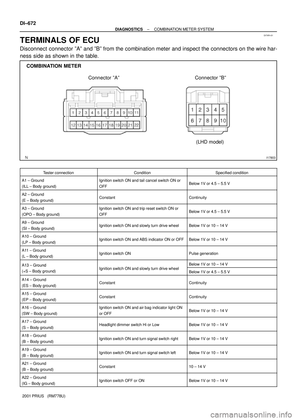
Disconnect connector ºAº and ºBº from the combination meter and inspect the connectors on the wire har-
ness side as shown in the table.
Tester connectionConditionSpecified condition
A1 ± Ground
(ILL ± Body ground)Ignition switch ON and tail cancel switch ON or
OFFBelow 1V or 4.5 ± 5.5 V
A2 ± Ground
(E ± Body ground)ConstantContinuity
A3 ± Ground
(OPO ± Body ground)Ignition switch ON and trip reset switch ON or
OFFBelow 1V or 4.5 ± 5.5 V
A9 ± Ground
(SI ± Body ground)Ignition switch ON and slowly turn drive wheelBelow 1V or 10 ± 14 V
A10 ± Ground
(LP ± Body ground)Ignition switch ON and ABS indicator ON or OFFBelow 1V or 10 ± 14 V
A11 ± Ground
(L ± Body ground)Ignition switch ONPulse generation
A13 ± GroundI iti it h ON d l l t d i h lBelow 1V or 10 ± 14 VA13 Ground
(+S ± Body ground)Ignition switch ON and slowly turn drive wheelBelow 1V or 4.5 ± 5.5 V
A14 ± Ground
(ES ± Body ground)ConstantContinuity
A15 ± Ground
(EP ± Body ground)ConstantContinuity
A16 ± Ground
(SW ± Body ground)Ignition switch ON and air bag indicator light ON
or OFFBelow 1V or 10 ± 14 V
A17 ± Ground
(S ± Body ground)Headlight dimmer switch Hi or LowBelow 1V or 10 ± 14 V
A18 ± Ground
(B ± Body ground)Ignition switch ON and turn signal switch rightBelow 1V or 10 ± 14 V
A19 ± Ground
(B ± Body ground)Ignition switch ON and turn signal switch leftBelow 1V or 10 ± 14 V
A21 ± Ground
(B ± Body ground)Constant10 ± 14 V
A22 ± Ground
(IG ± Body ground)Ignition switch OFF or ONBelow 1V or 10 ± 14 V