2001 TOYOTA LAND CRUISER remote control
[x] Cancel search: remote controlPage 12 of 142
’01 L/C U (L/O 0008)
10
Keys
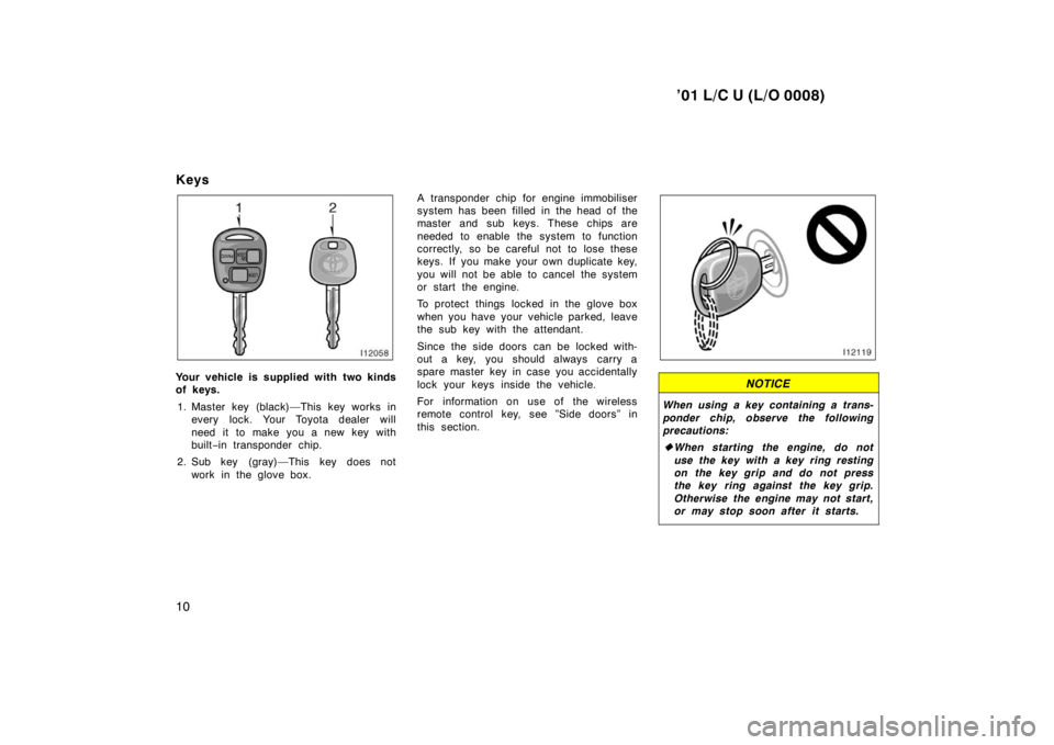
Your vehicle is supplied with two kinds
of keys.
1. Master key (black)—This key works in every lock. Your Toyota dealer will
need it to make you a new key with
built −in transponder chip.
2. Sub key (gray)—This key does not work in the glove box. A transponder chip for engine immobiliser
system has been filled in the head of the
master and sub keys. These chips are
needed to enable the system to function
correctly, so be careful not to lose these
keys. If you make your own duplicate key,
you will not be able to cancel the system
or start the engine.
To protect things locked in the glove box
when you have your vehicle parked, leave
the sub key with the attendant.
Since the side doors can be locked with-
out a key, you should always carry a
spare master key in case you accidentally
lock your keys inside the vehicle.
For information on use of the wireless
remote control key, see ”Side doors” in
this section.NOTICE
When using a key containing a trans-
ponder chip, observe the following
precautions: �
When starting the engine, do not
use the key with a key ring resting
on the key grip and do not press
the key ring against the key grip.
Otherwise the engine may not start,
or may stop soon after it starts.
Page 17 of 142
’01 L/C U (L/O 0008)15
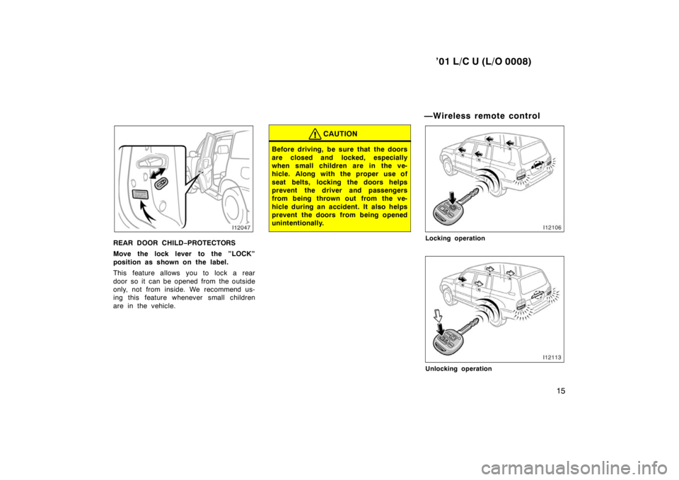
REAR DOOR CHILD−PROTECTORS
Move the lock lever to the ”LOCK”
position as shown on the label.
This feature allows you to lock a rear
door so it can be opened from the outside
only, not from inside. We recommend us-
ing this feature whenever small children
are in the vehicle.
CAUTION
Before driving, be sure that the doors
are closed and locked, especially
when small children are in the ve-
hicle. Along with the proper use of
seat belts, locking the doors helps
prevent the driver and passengers
from being thrown out from the ve-
hicle during an accident. It also helps
prevent the doors from being opened
unintentionally.
—Wireless remote control
Locking operation
Unlocking operation
Page 18 of 142
’01 L/C U (L/O 0008)
16
Your vehicle has a wireless remote
control system that can lock or unlock
all the side doors and back door from a
distance within approximately 1 m (3
ft.) of the vehicle.
LOCKING AND UNLOCKING THE SIDE
DOORS AND BACK DOOR
To lock and unlock all the side doors
and back door, push the switches slow-
ly and securely. At this time, the indica-
tor light on the key grip flashes once.
To lock: Push the ”LOCK” switch. All the
side doors and back door are locked si-
multaneously. At this time, parking lights
and tail lights flash once.
Check to see that all the side doors and
back door are securely locked.
If any of the side doors or back door is
not securely closed, or if the key is in the
ignition switch, locking cannot be per-
formed by the ”LOCK” switch.
To unlock: Push the ”UNLOCK” switch
once to unlock the driver ’s door alone.
Pushing the switch twice within 3 seconds
unlocks all the side doors and back door
simultaneously. At this time, parking lights
and tail lights flash twice.
Together with the activation of unlocking,
the interior light comes on for 15 seconds
if the interior light switch is in “DOOR”
position. However, this function does not
work when the ignition key is in the “ON”
position. (For detailed information, see “In-
terior light” in Section 1
−4.)
You have 30 seconds to open a door after
using the wireless remote unlock feature.
If a door is not opened by then, all the
side doors and back door will be automati-
cally locked again.
If the ”LOCK” or ”UNLOCK” switch is kept
pressed in, the locking or unlocking opera-
tion is not repeated. Release the button
and then push again.
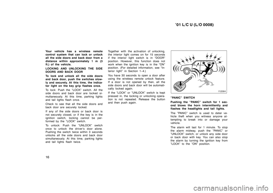
”PANIC” SWITCH
Pushing the ”PANIC” switch for 1 sec-
ond blows the horn intermittently and
flashes the headlights and tail lights.
The ”PANIC” switch is used to deter ve-
hicle theft when you witness anyone at-
tempting to break into or damage your
vehicle.
The alarm will last for 1 minute. To stop
the alarm midway, push the ”PANIC” or
”UNLOCK” switch, or unlock any side door
or back door with key. You can also stop
the alarm by turning the ignition key from
”LOCK” to the ”ON” position.
Page 19 of 142
’01 L/C U (L/O 0008)17
The ”PANIC” mode does not work when
the ignition key is in the ”ON” position.
WIRELESS REMOTE CONTROL KEY
The wireless remote control key is an
electronic component. Observe the follow-
ing instructions in order not to cause dam-
age and trouble on the key.
� Do not leave the key on places where
the temperature becomes high such as
on the dashboard.
� Do not disassemble it.
� Avoid knocking it hard against other
objects or dropping it.
� Avoid putting it in water.
You can use up to 4 wireless remote con-
trol keys for the same vehicle. Contact
your Toyota dealer for detailed information. If the wireless remote control key does
not actuate the doors or operate from a
normal distance, or the indicator light on
the key is dimmed or does not come on:
� Check for closeness to a radio trans-
mitter such as a radio station or an
airport which can interfere with normal
operation of the key.
� The battery may have been consumed.
Check the battery in the key. To
replace the battery, see following
”REPLACING THE BATTERY”.
If you lose your wireless remote control
key, contact your Toyota dealer as soon
as possible to avoid the possibility of
theft, or an accident. (For detailed infor-
mation, see “If you lose your keys” in
Section 4.)
For vehicles sold in U.S.A.
This device complies with Part 15 of the
FCC Rules. Operation is subject to the
following two conditions: (1) This device
may not cause harmful interference, and
(2) this device must accept any interfer-
ence received, including interference
that may cause undesired operation.
NOTICE:
This equipment has been tested and
found to comply with the limits for a
Class B digital device, pursuant to Part
15 of the FCC Rules. These limits are
designed to provide reasonable protec-
tion against harmful interference in a
residential installation. This equipment
generates, uses and can radiate radio
frequency energy and, if not installed
and used in accordance with the instruc-
tions, may cause harmful interference to
radio communications. However, there is
no guarantee that interference will not
occur in a particular installation. If this
equipment does cause harmful interfer-
ence to radio or television reception,
which can be determined by turning the
equipment off and on, the user is en-
couraged to try to correct the interfer-
ence by one or more of the following
measures: � Reorient or relocate the receiving an-
tenna.
� Increase the separation between the
equipment and receiver.
Page 29 of 142

’01 L/C U (L/O 0008)27
The system will automatically be set after
30 seconds. When the system is set, the
indicator light will start flashing again.
4. After making sure the indicator light starts flashing, you may leave the ve-
hicle.
Never leave anyone in the vehicle when
you set the system, because unlocking
from the inside will activate the system.
WHEN THE SYSTEM IS SET
Activating the system
The system will give the alarm under the
following conditions: � If any of the side doors is unlocked or
opened without the key or wireless re-
mote control key, or if the back door
or hood is forcibly opened
� If the battery terminal is disconnected
and then reconnected
The indicator light will come on when the
system is activating. If any of the side door or back door is
unlocked without the key or wireless re-
mote control key and the key is not in the
ignition switch, all the side doors and
back door will be automatically locked
again.
After one minute, the alarm will automati-
cally stop and the indicator light will starts
flashing again.
Reactivating the alarm
Once set, the system automatically resets
the alarm after the alarm stops.
The alarm will activate again under the
same circumstances described in
”Activating the system”.
Stopping the alarm
The alarm will be stopped by the following
two ways:
� Turn the ignition key from the ”LOCK”
to ”ON” position.
� Unlock any of the side doors or back
door with the key or wireless remote
control key.
These ways cancel the system at the
same time. TESTING THE SYSTEM
1. Open all the windows.
2. Set the system as described above. The side doors and back door should
be locked with the key or wireless re-
mote control key. Be sure to wait until
the indicator light goes off or starts
flashing.
3. Unlock any side door or back door from the inside. The system should ac-
tivate the alarm.
4. Stopping the alarm as described above.
5. Repeat this operation for the other doors, back door and hood. When test-
ing on the hood, also check that the
system is activated when the battery
terminal is disconnected and then re-
connected.
If the system does not work properly,
have it checked by your Toyota dealer.
Page 135 of 142
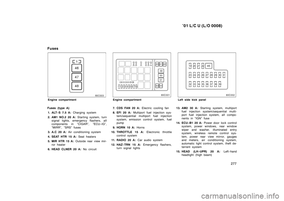
’01 L/C U (L/O 0008)277
Fuses
Engine compartment
Fuses (type A) 1. ALT −S 7.5 A: Charging system
2. AM1 NO.2 20 A: Starting system, turn
signal lights, emergency flashers, all
components in ”CIGAR”, ”ECU −IG”,
”MIRR”, ”SRS” fuses
3. A.C 20 A: Air conditioning system
4. SEAT HTR 15 A: Seat heaters
5. MIR HTR 15 A: Outside rear view mir-
ror heater
6. HEAD CLNER 20 A: No circuitEngine compartment
7. CDS FAN 20 A: Electric cooling fan
8. EFI 20 A: Multiport fuel injection sys-
tem/sequential multiport fuel injection
system, emission control system, fuel
pump
9. HORN 10 A: Horns
10. THROTTLE 15 A: Electronic throttle
control system
11. RADIO 20 A: Car audio system
12. HAZ −TRN 15 A: Emergency flashers,
turn signal lightsLeft side kick panel
13. AM2 30 A: Starting system, multiport
fuel injection system/sequential multi-
port fuel injection system, all compo-
nents in ”IGN” fuse
14. ECU −B1 20 A: Power door lock control
system, power wi ndows, rear window
wiper and washer, illuminated entry
system, wireless remote control sys-
tem, power rear view mirror, gauges
and meters, air conditioning system,
automatic light control system, theft de-
terrent system
15. HEAD (LH −UPR) 20 A: Left−hand
headlight (high beam)
Page 136 of 142

’01 L/C U (L/O 0008)
278
16. HEAD (RH
−UPR) 20 A: Right−hand
headlight (high beam)
17. HEAD (LH −LWR) 10 A: Left−hand
headlight (low beam), front fog lights
18. HEAD (RH −LWR) 10 A: Right−hand
headlight (low beam)
19. MIRR 10 A: Power rear view mirror
20. SRS 15 A: SRS airbag system, seat
belt pretensioners
21. CIGAR 15 A: Cigarette lighter, car au-
dio system, power antenna
22. IGN 10 A: Multiport fuel injection sys-
tem/sequential multiport fuel injection
system, anti −lock brake system, SRS
airbag system, seat belt pretensioners,
discharge warning light
23. DOME 10 A: Interior lights, personal
lights
24. AHC −IG 20 A: No circuit
25. DIFF 20 A: Rear differential lock sys-
tem 26. GAUGE 15 A:
Gauges and meters,
service reminder indicators and warning
buzzer (except discharge, open door
and SRS airbag warning lights), back −
up lights, air conditioning system, elec-
tronically controlled automatic transmis-
sion system, wireless remote control
system, daytime running light system
27. WIPER 25 A: Windshield wipers and
washer, rear window wiper and washer
28. I/UP 7.5 A: Engine idle up system
29. FR FOG 15 A: Front fog lights
30. STOP 15 A: Stop lights, high mounted
stoplight
31. RR A.C 30 A: Air conditioning system
32. DEFOG 20 A: Rear window defogger
33. ECU −B 15 A: Power tilt and telescopic
steering system, daytime running light
system, theft deterrent system
34. TAIL 15 A: Tail lights, license plate
lights, parking lights, instrument panel
lights
35. AHC −B 15 A: No circuit
36. OBD 10 A: On−board diagnosis system
37. RR HTR 10 A: Air conditioning system 38. ECU
−IG 15 A: Anti−lock brake system,
shift lock system, power seats, power
antenna, power tilt and telescopic
steering system
39. PWR OUTLET 15 A: Power outlets
Fuses (type B)
40. ABS NO.1 50 A: Anti
−lock brake sys-
tem
41. AHC 50 A: No circuit
42. ACC 50 A: All components in ”PWR
OUTLET” fuse
43. ABS NO.2 40 A: Anti−lock brake sys-
tem
44. STARTER 30 A: Starting system
45. POWER 40 A: Power door lock control
system, power wi ndows, electric moon
roof, power seat, power tilt and tele-
scopic steering system
Fuses (type C)
46. MAIN 100 A: No circuit
47. ALT 140 A: All components in ”J/B
NO.2”, ”MIR HTR”, ”AM1 NO.1”, ”ACC”,
”CDS FAN”, ”HTR” and ”ABS NO.1”
fuses
48. J/B NO.2 100 A: All components in
”ECU −B”, ”FR FOG”, ”DEFOG”, ”AHC −
B”, ”TAIL”, ”STOP”, ”DOME”, ”POWER”,
”OBD”, ”RR A.C” and ”RR HTR” fuses