Page 2480 of 2572

TERMINALS OF ECU
SKID CONTROL ECU:
Symbols (Terminals No.)")
05IOX-02
F45156
S27
F45157
GND 05-742
- DIAGNOSTICSTIRE PRESSURE WARNING SYSTEM
932 Author�: Date�:
2005 HIGHLANDER REPAIR MANUAL (RM1144U)
TERMINALS OF ECU
SKID CONTROL ECU:
Symbols (Terminals No.)Wiring ColorTerminal DescriptionConditionSpecified Condition
TRC+ (8) - TRC- (22)G-B - Y-BECM communication out-
putIgnition switch ONPulse generation
ENG+ (9) - GND1 (32)W-L - W-BECM serial communica-
tion line (+) input signalIgnition switch ON and vehicle
speed 30 km/h (19 mph) or morePulse generation
(See wave form 1)
D/G (13) - GND1 (32)GR-B - W-BDiagnosis tester commu-
nication lineIgnition switch ON10 to 14 V
ENG- (23) - GND1 (32)W-G - W-BECM serial communica-
tion line (-) input signalIgnition switch ON and engine idle
speedPulse generation
(See wave form 2)
STP (27) - GND1 (32)G-Y - W-BStop lamp switch assy in-
put signalBrake pedal depressed10 to 14 V
STP (27) - GND1 (32)G-Y - W-BStop lamp switch assy in-
put signalBrake pedal releasedBelow 1.5 V
GND1 (32) - Body groundW-B -
Body groundGroundAlwaysBelow 1 W
INIT (41) - GND1 (32)B-Y - W-BTire pressure warning re-
set switch signalIgnition switch ON and tire pressure
warning reset switch ONBelow 3 V
INIT (41) - GND1 (32)B-Y - W-BTire pressure warning re-
set switch signalIgnition switch ON and tire pressure
warning reset switch OFF10 to 14 V
Wave form 1:
Reference
ItemCondition
TerminalENG+ - GND1
Tool setting1 V / DIV, 0.5 ms / DIV
Vehicle conditionEngine idle speed
Page 2481 of 2572
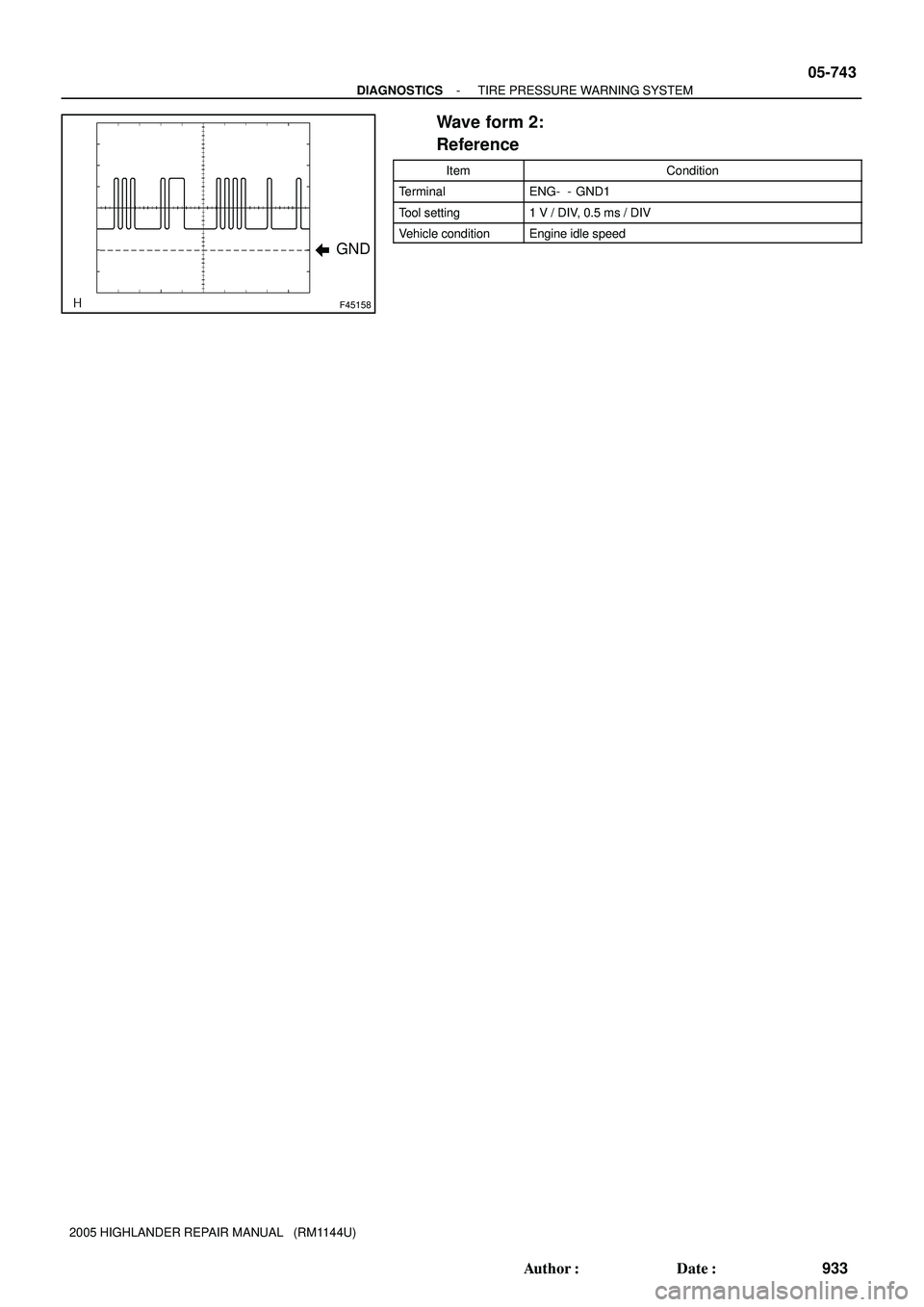
F45158
GND
- DIAGNOSTICSTIRE PRESSURE WARNING SYSTEM
05-743
933 Author�: Date�:
2005 HIGHLANDER REPAIR MANUAL (RM1144U)
Wave form 2:
Reference
ItemCondition
TerminalENG- - GND1
Tool setting1 V / DIV, 0.5 ms / DIV
Vehicle conditionEngine idle speed
Page 2482 of 2572

TORQUE SPECIFICATION
2AZ-FE
Part TightenedNVmkgfVcmftVlbf
Starter assy
Starter")
0304O-04
03-32
- SERVICE SPECIFICATIONSSTARTING & CHARGING
153 Author�: Date�:
2005 HIGHLANDER REPAIR MANUAL (RM1144U)
TORQUE SPECIFICATION
2AZ-FE
Part TightenedNVmkgfVcmftVlbf
Starter assy
Starter assy x Engine3737727
Starter wire x Terminal 30 of starter9.81007.0
Starter drive housing assy x Magnet switch assy7.57666 in.Vlbf
Starter commutator end frame assy x Starter drive housing assy6.06153 in.Vlbf
Lead wire of starter yoke x Terminal C of magnet switch assy101027.0
Battery clamp x Battery clamp bolt5.55649 in.Vlbf
Cable x Battery terminal3.53631 in.Vlbf
Generator assy (100A)
Generator assy x Engine M8
M1021
52214
53015
38
Generator wire x Generator assy9.81007.0
Generator rectifier end frame x Drive end frame assy5.85951 in.Vlbf
Generator brush holder assy x Generator rectifier end frame1.81816 in.Vlbf
Generator rear end cover x Generator rectifier end frame4.64741 in.Vlbf
Retainer plate x Drive end frame assy generator2.32320 in.Vlbf
Generator pulley x Generator rotor assy11 01,12281
Generator assy (130A)
Generator assy x Engine M8
M1021
52214
53015
38
Generator wire x Generator assy9.81007.0
Generator rectifier end frame x Drive end frame assy5.85951 in.Vlbf
Generator brush holder assy x Generator rectifier end frame1.81816 in.Vlbf
Generator rear end cover x Generator rectifier end frame4.64741 in.Vlbf
Retainer plate x Drive end frame assy generator2.32320 in.Vlbf
Generator pulley x Generator rotor assy11 01,12281
3MZ-FE
Part TightenedNVmkgfVcmftVlbf
Starter assy
Starter assy x Engine3737727
Starter wire x Terminal 30 of starter9.81007.0
Starter drive housing assy x Magnet switch assy7.57666 in.Vlbf
Starter commutator end frame assy x Starter drive housing assy6.06153 in.Vlbf
Lead wire of starter yoke x Terminal C of magnet switch assy101027.0
Battery clamp x Battery clamp bolt5.55649 in.Vlbf
Cable x Battery terminal3.53631 in.Vlbf
Generator assy (100A)
Generator assy x Generator bracket No. 25859243
Generator assy x Generator belt adjusting bar1818413
Generator wire x Generator assy9.81007.0
Generator rectifier end frame x Drive end frame assy5.85951 in.Vlbf
Generator brush holder assy x Generator rectifier end frame1.81816 in.Vlbf
Generator rear end cover x Generator rectifier end frame4.64741 in.Vlbf
Retainer plate x Drive end frame assy generator2.32320 in.Vlbf
Generator pulley x Generator rotor assy11 01,12281
Generator assy (130A)
Generator assy x Generator bracket No. 25859243
Generator assy x Generator belt adjusting bar1818413
Generator wire x Generator assy9.81007.0
Page 2485 of 2572

F00052
4
1
T6
05-860
- DIAGNOSTICSABS WITH EBD & BA & TRAC & VSC SYSTEM
1050 Author�: Date�:
INSPECTION PROCEDURE
HINT:
Start the inspection from step 1 when using the hand-held tester and start from step 2 when not using the
hand-held tester.
1 PERFORM ACTIVE TEST BY HAND-HELD TESTER(TRAC OFF INDICATOR
LIGHT)
(a) Connect the hand-held tester to the DLC3.
(b) Start the engine.
(c) Select the item ºTRAC OFF LIGHTº in the ACTIVE TEST and operate the TRAC OFF indicator light
on the hand-held tester.
ItemVehicle Condition / Test DetailsDiagnostic Note
VSC / TRAC OFF INDTurns VSC / TRAC OFF indicator ON / OFFObserve combination me-
ter
(d) Check that ºONº and ºOFFº of the TRAC OFF indicator light are indicated on the combination meter
when using the hand-held tester.
OK:
Turn the TRAC OFF indicator light on or off in accordance with the hand-held tester.
NG Go to step 6
OK
2 INSPECT TRACTION CONTROL SWITCH
(a) Remove the TRAC control switch.
(b) Disconnect the TRAC control switch connector T6.
(c) Measure the resistance according to the value(s) in the
table below.
Standard:
Tester ConnectionSwitch ConditionSpecified Condition
T6 4 T6 1Pushed in (ON)Below 1 WT6-4 - T6-1Released (OFF)10 kW or higher
NG REPLACE TRACTION CONTROL SWITCH
OK
Page 2504 of 2572
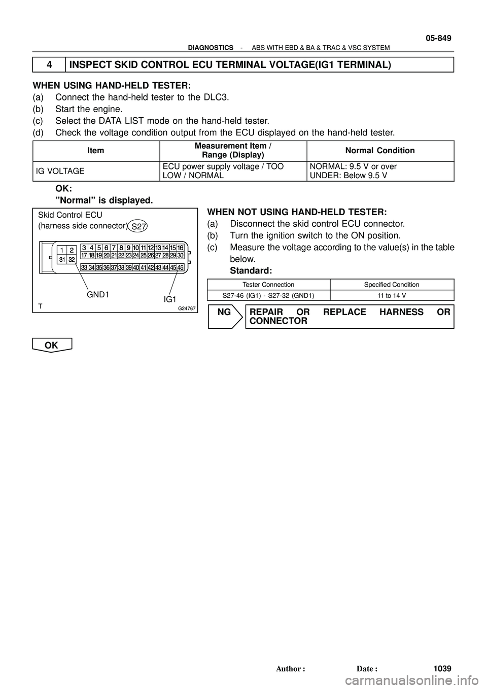
G24767
GND1IG1
Skid Control ECU
(harness side connector)
S27
- DIAGNOSTICSABS WITH EBD & BA & TRAC & VSC SYSTEM
05-849
1039 Author�: Date�:
4 INSPECT SKID CONTROL ECU TERMINAL VOLTAGE(IG1 TERMINAL)
WHEN USING HAND-HELD TESTER:
(a) Connect the hand-held tester to the DLC3.
(b) Start the engine.
(c) Select the DATA LIST mode on the hand-held tester.
(d) Check the voltage condition output from the ECU displayed on the hand-held tester.
ItemMeasurement Item /
Range (Display)Normal Condition
IG VOLTAGEECU power supply voltage / TOO
LOW / NORMALNORMAL: 9.5 V or over
UNDER: Below 9.5 V
OK:
ºNormalº is displayed.
WHEN NOT USING HAND-HELD TESTER:
(a) Disconnect the skid control ECU connector.
(b) Turn the ignition switch to the ON position.
(c) Measure the voltage according to the value(s) in the table
below.
Standard:
Tester ConnectionSpecified Condition
S27-46 (IG1) - S27-32 (GND1)11 to 14 V
NG REPAIR OR REPLACE HARNESS OR
CONNECTOR
OK
Page 2507 of 2572

S27
VSCW
05-852
- DIAGNOSTICSABS WITH EBD & BA & TRAC & VSC SYSTEM
1042 Author�: Date�:
INSPECTION PROCEDURE
1 CHECK VSC WARNING LIGHT
WHEN USING HAND")
G24767
Skid Control ECU
(harness side connector)
S27
VSCW
05-852
- DIAGNOSTICSABS WITH EBD & BA & TRAC & VSC SYSTEM
1042 Author�: Date�:
INSPECTION PROCEDURE
1 CHECK VSC WARNING LIGHT
WHEN USING HAND-HELD TESTER:
(a) Connect the hand-held tester to the DLC3 and start the engine.
(b) Select the item ºVSC WARN LIGHTº in the ACTIVE TEST and operate the VSC warning light on the
hand-held tester.
(c) Check that ºONº and ºOFFº of the VSC warning light are indicated on the combination meter when us-
ing the hand-held tester.
ItemVehicle Condition / Test DetailsDiagnostic Note
VSC WARN LIGHTTurns VSC warning light ON / OFFObserve combination me-
ter
OK:
Turn the VSC warning light ON or OFF in accordance with the hand-held tester.
WHEN NOT USING HAND-HELD TESTER:
(a) Turn the ignition switch off and disconnect the connector
from the skid control ECU.
(b) Ground the terminal VSCW of skid control ECU.
(c) Turn the ignition switch to the ON position.
(d) Check that the VSC warning light.
OK:
Turn the light ON or OFF in accordance with the con-
necting condition of terminal VSCW and body
ground.
NG CHECK AND REPAIR VSC WARNING LIGHT
CIRCUIT (SEE PAGE 05-1868)
OK
Page 2509 of 2572

31-9
3087 Author�: Date�:
TRANSFER ASSY (4WD)
OVERHAUL
HINT:
COMPONENT:
3MZ-FE ENGINE: See page 14-134
2AZ-FE ENGIN")
31050-02
C82977
No.2 Plug
No.1 Plug
Drain Plug
F45388
- TRANSFERTRANSFER ASSY (4WD)
31-9
3087 Author�: Date�:
TRANSFER ASSY (4WD)
OVERHAUL
HINT:
COMPONENT:
3MZ-FE ENGINE: See page 14-134
2AZ-FE ENGINE: See page 14-15
AUTOMATIC TRANSMISSION (U151E/U151F): See page 40-18
TRANSFER: See page 31-3
1. REMOVE ENGINE ASSEMBLY WITH TRANSAXLE (3MZ-FE ENGINE TYPE)
(SEE PAGE 14-149)
2. REMOVE ENGINE ASSEMBLY WITH TRANSAXLE (2AZ-FE ENGINE TYPE)
(SEE PAGE 14-24)
3. REMOVE TRANSFER CASE NO.1 PLUG
(a) Remove the transfer case No.1 plug.
(b) Remove the gasket No.1 from the transfer case No.1
plug.
4. REMOVE TRANSFER CASE NO.2 PLUG
(a) Remove the transfer case No.2 plug.
(b) Remove the gasket No.2 from the transfer case No.2 plug.
5. REMOVE TRANSFER DRAIN PLUG
(a) Remove the transfer drain plug and bleed the transfer oil.
(b) Remove the drain gasket from the transfer drain plug.
6. REMOVE TRANSFER STIFFENER PLATE RH (2AZ-FE
ENGINE TYPE)
(a) Remove the 5 bolts and the stiffener plate RH.
7. REMOVE ENGINE MOUNTING BRACKET RR (2AZ-FE ENGINE TYPE)
(a) Remove the 3 bolts and the engine mounting bracket RR.
8. REMOVE AUTOMATIC TRANSMISSION W/TRANSFER (3MZ-FE ENGINE TYPE)
(SEE PAGE 40-20)
Page 2535 of 2572

31-35
3113 Author�: Date�:
(b) Install the transfer assy to the transaxle assy with the 2
bolts and 6 nuts.
Torque: 69")
C82785
F45388
C82977
No.2 PlugNo.1 Plug
Drain Plug
- TRANSFERTRANSFER ASSY (4WD)
31-35
3113 Author�: Date�:
(b) Install the transfer assy to the transaxle assy with the 2
bolts and 6 nuts.
Torque: 69 NVm (700 kgfVcm, 51 ftVlbf)
NOTICE:
�Check that the gasket is installed to the transfer assy
before instaling them to the transaxle assy.
�Install the transfer assy to the transaxle assy without
tilting.
�When moving the transfer assy, do not hold the oil
seal on the both sides.
83. INSTALL ENGINE MOUNTING BRACKET RR (2AZ-FE ENGINE TYPE)
(a) Install the engine mounting bracket RR with the 3 bolts.
Torque: 64 NVm (652 kgfVcm, 47 ftVlbf)
84. INSTALL TRANSFER STIFFENER PLATE RH (2AZ-FE
ENGINE TYPE)
(a) Install the stiffener plate RH with the 5 bolts.
Torque: 34 NVm (350 kgfVcm, 25 ftVlbf)
85. INSTALL AUTOMATIC TRANSMISSION W/TRANSFER (3MZ-FE ENGINE TYPE)
(SEE PAGE 40-20)
86. INSTALL ENGINE ASSEMBLY WITH TRANSAXLE (3MZ-FE ENGINE TYPE) (SEE PAGE 14-149)
87. INSTALL ENGINE ASSEMBLY WITH TRANSAXLE (2AZ-FE ENGINE TYPE) (SEE PAGE 14-24)
88. INSTALL TRANSFER DRAIN PLUG
(a) Install the transfer drain plug with a new drain gasket.
Torque: 49 NVm (500 kgfVcm, 36 ftVlbf)
89. INSTALL TRANSFER CASE NO.2 PLUG
(a) Install the transfer case No.2 plug with a new gasket No.2.
Torque: 49 NVm (500 kgfVcm, 36 ftVlbf)
90. INSTALL TRANSFER CASE NO.1 PLUG
(a) Add oil up to 0 to 5 mm below the lower side of the plug
hole.
Oil quantity: 0.9 L (0.95 US qts, 0.79 lmp. qts)
HINT:
When adding oil, pour it slowly.
(b) Install the transfer case No.1 plug with a new gasket No.1.
Torque: 49 NVm (500 kgfVcm, 36 ftVlbf)