Page 2252 of 2572
I44266
ECM
E2
THW E719 E728
BR
G-BBR*1
1
2 5
S29 S285
E2
Engine
Coolant
Temp Sensor Short ConnectorC11
Combination Meter Assy
BEANMPX- 21
*1: 2AZ-FE
*2: 3MZ-FEW-B*2 BR
05-1896
- DIAGNOSTICSCOMBINATION METER
2086 Author�: Date�:
MALFUNCTION IN WATER TEMPERATURE RECEIVER GAUGE
WIRING DIAGRAM
INSPECTION PROCEDURE
HINT:
If there is an open or short in the engine coolant temperature sensor circuit, the ECM outputs DTCs. Perform
troubleshooting with the ºSFI System 05-5,.05-366º.
1 PERFORM ACTIVE TEST BY HAND-HELD TESTER
(a) Operate the hand-held tester according to the steps on the display and select the ºACTIVE TESTº.
METER:
ItemTest DetailsDiagnostic Note
COOLANT TEMPLOW / NORMAL / HI-
OK:
Needle indication is normal.
NG REPLACE COMBINATION METER ASSY
(SEE PAGE 71-18)
OK
05IQ0-05
Page 2253 of 2572
- DIAGNOSTICSCOMBINATION METER
05-1897
2087 Author�: Date�:
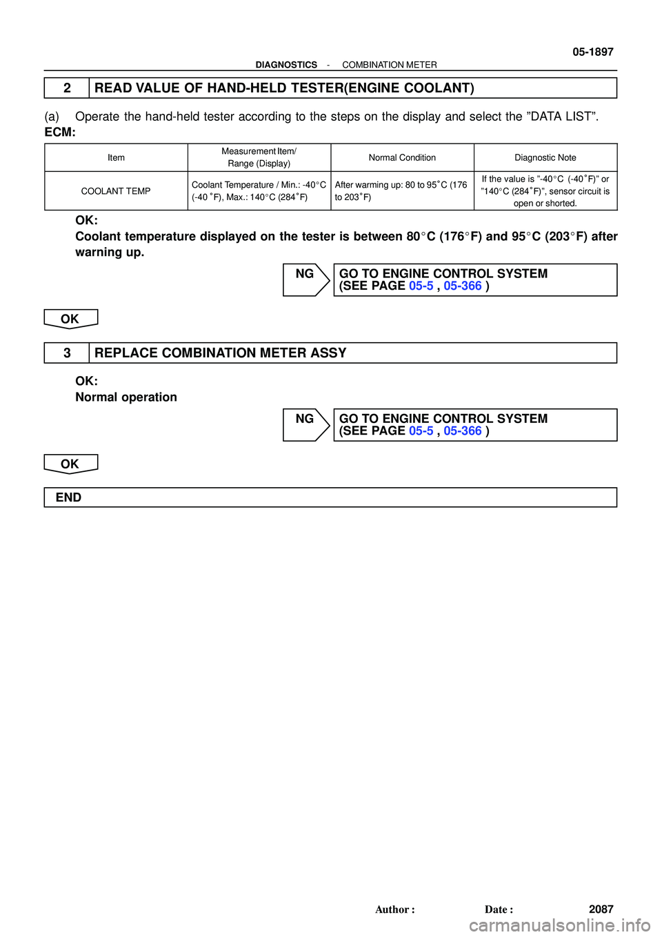
2 READ VALUE OF HAND-HELD TESTER(ENGINE COOLANT)
(a) Operate the hand-held tester according to the steps on the display and select the ºDATA LISTº.
ECM:
ItemMeasurement Item/
Range (Display)Normal ConditionDiagnostic Note
COOLANT TEMPCoolant Temperature / Min.: -40�C
(-40°F), Max.: 140�C (284°F)After warming up: 80 to 95°C (176
to 203°F)If the value is º-40�C (-40°F)º or
º140�C (284°F)º, sensor circuit is
open or shorted.
OK:
Coolant temperature displayed on the tester is between 80�C (176�F) and 95�C (203�F) after
warning up.
NG GO TO ENGINE CONTROL SYSTEM
(SEE PAGE 05-5, 05-366)
OK
3 REPLACE COMBINATION METER ASSY
OK:
Normal operation
NG GO TO ENGINE CONTROL SYSTEM
(SEE PAGE 05-5, 05-366)
OK
END
Page 2256 of 2572

SPARK TEST
1. Turn ignition switch ON.
2. Check that there is battery voltage at ignition coil positive (+)
terminal.
CHECK IF WIRE HARNESS")
18091-05
CHECK POWER SUPPLY TO IGNITION COIL (WITH
IGNITER)
SPARK TEST
1. Turn ignition switch ON.
2. Check that there is battery voltage at ignition coil positive (+)
terminal.
CHECK IF WIRE HARNESS SIDE CONNECTOR OF
IGNITION COIL (WITH IGNITER) IS SECUREConnect securely.
Check wiring between ignition switch to
ignition coil (with igniter).
NG
OK
OKNG
NG PERFORM SPARK TEST WITH A DIFFERENT
IGNITION COIL (WITH IGNITER)
1. Replace current ignition coil (with igniter) with a different,
functioning ignition coil (with igniter).
2. Perform spark test again.
OKIf sparks occur, replace faulty ignition coil
(with igniter).
NG
Continue on next page
Standard:ColdHot
1,060 to 1,645 W
OKNG
835 to 1,400 WReplace camshaft position sensor. CHECK RESISTANCE OF CAMSHAFT POSITION
SENSOR (See page 18-5)
- IGNITIONIGNITION SYSTEM (2AZ-FE)
18-1
2861 Author�: Date�:
IGNITION SYSTEM (2AZ-FE)
ON-VEHICLE INSPECTION
NOTICE:
In this section, the terms coldº and hotº refer to the temperature of the coils. ºColdºmeans approxi-
mately -10�C (14�F) to 50�C (122�F). ºHotº means approximately 50�C (122�F) to 100�C (212�F).
1. INSPECT IGNITION COIL ASSY (WITH IGNITER) AND PERFORM SPARK TEST
(a) Check for DTCs.
NOTICE:
If a DTC is present, perform a troubleshooting in accordance with the procedure for that DTC.
(b) Check if sparks occur.
(1) Remove the engine cover No. 1 (see page 14-24).
(2) Remove the ignition coils.
(3) Using a 16 mm (0.63 in.) plug wrench, remove the spark plugs.
(4) Install the spark plugs to each ignition coil and connect the ignition coil connectors.
(5) Disconnect the 4 injector connectors.
(6) Ground the spark plugs.
(7) Check if sparks occur at each spark plug while the engine is being cranked.
NOTICE:
�Be sure to ground the spark plug when checking.
�Replace the ignition coil if given physical impact is given to the coil.
�Do not crank the engine for more than 2 seconds.
If the sparks do not occur, do the following test:
Page 2257 of 2572
Replace crankshaft position sensor. CHECK RESISTANCE OF CRANKSHAFT POSITION
Standard:Cold Hot
985 to 1,600 W1,265 to 1,890 W
CHECK IGT SIGNAL FROM ECM
REPAIR WIRING BETWEEN IGNITION COIL AND ECM
OKNG
NG SENSOR (See page 18-6)
OK (See page 05-174)Check ECM (see page 05-32).
OK Continued from previous page 18-2
- IGNITIONIGNITION SYSTEM (2AZ-FE)
2862 Author�: Date�:
(8) Using a 16 mm (0.63 in.) plug wrench, install the spark plugs.
Torque: 19 NVm (194 kgfVcm, 14 ftVlbf)
(9) Install the ignition coils.
Torque: 9.0 NVm (92 kgfVcm, 80 in.Vlbf)
(10) Install the engine cover No. 1.
Torque: 9.0 NVm (92 kgfVcm, 80 in.Vlbf)
Page 2258 of 2572

2370 Author�: Date�:
2005 HIGHLANDER REPAIR MANUAL (RM1144U)
SFI SYSTEM (3MZ-FE)
ON-VEHICLE INSPECTION
1. CHECK THROTTLE BODY
(a) Listen to")
100FS-06
10-12
- ENGINE CONTROL SYSTEMSFI SYSTEM (3MZ-FE)
2370 Author�: Date�:
2005 HIGHLANDER REPAIR MANUAL (RM1144U)
SFI SYSTEM (3MZ-FE)
ON-VEHICLE INSPECTION
1. CHECK THROTTLE BODY
(a) Listen to the throttle control motor operating sounds.
(1) Turn the ignition switch ON.
(2) When pressing the accelerator pedal position sensor lever, listen to the running motor. Make sure
no friction noise comes from the motor.
If friction noise exists, replace the throttle body.
(b) Inspect the throttle position sensor.
(1) Connect the hand-held tester or OBD II scan tool to the DLC3.
(2) Turn the ignition switch ON.
(3) Check that the MIL is off.
(4) Under CURRENT DATA, the throttle valve opening percentage (THROTTLE POS) should be
within the standard value range below.
Standard throttle valve opening percentage:
60 % or more
If the percentage is less than 60 %, replace the throttle position sensor.
NOTICE:
When checking the standard throttle valve opening percentage, the transmission should be in the
neutral position.
2. CHECK ACCELERATOR PEDAL POSITION SENSOR
(a) Turn the ignition switch ON. Under CURRENT DATA, the voltage of the throttle position sensor should
be within the standard value range below.
Standard: 0.6 to 1.0 V
If the result is not as specified, replace the accelerator pedal position sensor.
3. CHECK CAMSHAFT TIMING OIL CONTROL VALVE (OCV) ASSY
(a) Connect the hand-held tester or OBD II scan tool to the DLC3.
(b) Turn the ignition switch ON.
(c) Start the engine and warm it up.
(d) Select the VVT from the ACTIVE TEST menu.
(e) Check the engine speed when the OCV is operated by the hand-held tester or OBD II scan tool.
Standard:
ConditionSpecified Condition
VVT system is OFF (OCV is OFF)Normal engine speed
VVT system is ON (OCV is ON)Rough idle or engine stalled
If the result is not as specified, replace the OCV assy.
Page 2259 of 2572

M OVERALL ELECTRICAL WIRING DIAGRAM
34
2 1
1 HIGHLANDER
2ACC
IG1
IG2
ST2 AM1 4
Engine Cont rol Module
<2- 8><3- 6><3- 7> 6
8 7AM2
W- R(
*1)
B
W1C 6
1A 1
10
Engine Cont rol")
2005 HIGHLANDER (EWD592U)
M OVERALL ELECTRICAL WIRING DIAGRAM
34
2 1
1 HIGHLANDER
2ACC
IG1
IG2
ST2 AM1 4
Engine Cont rol Module
<2- 8><3- 6><3- 7> 6
8 7AM2
W- R(
*1)
B
W1C 6
1A 1
10
Engine Cont rol
Module< 2- 7> < 3- 6>
140A ALT2
W- R W- R 2 1
3 5
22
1A
B1N P
41F 6
W- R 1C 4
EFLeft Side of
Cy linder Block 1IC3 1
W- R STARTER
Relay
42 42 42 42 42 42 13 13 13 13 13 13
BB
GR
B- WW L- Y
W- B W- B W- B W- B RRRRR(
*1)
WYORR R- L(
*1) R P R Y- BR L- Y R(
*1) G- Y(
*1) R(
*1) L- R(
*1)
W- B W- R W- B W- R W- B W- R W- B W- R W- B(
*1) W- G(
*1) W- B(
*1) W- R(
*1)
W- B
BRW- R W- R
Starting and Ignition Power Source
15A IG2
40A AM1
12
1
EC Left Side of
the Cylinder Head 2 2 2IC1 1IC1
30A AM2
2 2
7. 5 A ST ARTER
3W
4 EB13 EB2
L
Engine Contr ol
Module< 2- 6> < 3- 8>
FL MAIN
3. 0W W- RB- R
B- W
1
1C1
1G GR
* 1 : 3MZ- FE
* 2 : 2AZ- FE
W- B
(
*1) (
*2)
1
2
(
*1)
(
*1) G
Under the
Left HeadlightEH A ST1
3IC1 B 1BB-Y
P 1
5 4 EB2
B- R
L- W
B
Engine Control
Module<2- 6><3- 8>B- R
BB
B- WW- B
2EB1
BRW- R
R- W(
*2)
4A
4BA
B
C
(
Cont. next page)
W
W
G
I15
J 2 F 7
S 1(
A)
, S 2(
B)
S28(
A)
, S29(
B)
I 2 I 3 I 4 I 5 I 6 I 7
N 1
Fusible Link Block
Ignition Coil and
Igniter No. 1 Ignition Coil and
Igniter No. 2 Ignition Coil and
Igniter No. 3 Ignition Coil and
Igniter No. 4 Ignition Coil and
Igniter No. 5 Ignition Coil and
Igniter No. 6
Ignition SW
Junc tion
Connec tor
Noise Filt er
(
Ignition System)
Park/Neutral
Position SW
Starter
Short Connector GND IGF GND IGF I GFGND GND IGF IGFGN D GN D I GF +B IGT +B IGT I GT+B +B I GT I GT+B +B I GT
Page 2260 of 2572
2005 HIGHLANDER (EWD592U)
M
78
6 5
1 HIGHLANDER (
Cont' d)
4A
L
1 A
2 A
1 B S
IG
B1B 51C 7
8EB2
W- LR W
R- B 10A ECU- IG
Charging
2H 12I 1
7. 5A ALT- S
10 EB2
W- L WG
W- LR
A
B
C
1K 13
10 A HEAT ER
111
BCh ar g e
3B 12
3K 2
IBRi g ht I ns t r u me nt
Panel Br aceRBR
21 C 29 B 18 B
Multiplex Communication
System (
BEAN Bus)
<20- 3>
RL MPX2 MPX1
W- G3C 7 3A 4
P
W
W
G
E 6(
B)
, E 9(
C)
C11
G 1(
A)
, G 2(
B)
Combination Meter
Engine Cont rol Module
Ge ne r at or
Page 2261 of 2572

M OVERALL ELECTRICAL WIRING DIAGRAM
1
234
2 HIGHLANDER(
Cont. next page)
Engine Control (
3M Z- FE)
Power Source
YB- WW
EFI
RelayD
W IC1 4
RW
G
LGIC3 6
R
W
WW
1
2
2 2
B- W")
2005 HIGHLANDER (EWD592U)
M OVERALL ELECTRICAL WIRING DIAGRAM
1
234
2 HIGHLANDER(
Cont. next page)
Engine Control (
3M Z- FE)
Power Source
YB- WW
EFI
RelayD
W IC1 4
RW
G
LGIC3 6
R
W
WW
1
2
2 2
B- W
R
R
R R
A
B
6 7
L Y B W
CIRCUIT OPENING
Relay
R- W
B- WGY B
W- B
P- L
W- B L
W
BR
Y
W
K
P- L
G
R- WB- W
W
B
Y
LR R R R R 1
2
Y
G
W
W
WL- Y
QP ON MLJ C
IK3 13
A
Under the Left
HeadlightEH 52B 52G
32D 82B 42F5
3 1
2
Lef t Side of
Rear Cross MemberBCM 4
51 11 1
5 1
23 4E 1
61G
A/ F Rel ay2 2 2
2 1
3 5
R R R
5EB1
2
1 2
1 2
1 2
1 2
1 2
1 91G 41C 11G 11C
12I
20A
EFI NO. 1
2 GR
2
IC1 1
3
1
30A AM2
140A ALT
2W
10
Bat tery FL MAIN
3. 0W4M 4
7. 5A OBD
1E 10
1A 1BW
22B 72
2 1 2F B- W
B- W
G
2IC2
B
2A 7
W- BW- BP- L
14FB P
P
2B 4E W 2ACC
IG1
ST1
IG2
ST2 AM1 4
AM2
10A ETCS25A A/ F 15A IG2 10A IGN 10A EFI NO. 2
W40A AM1
1C 6
G10A HEATER1C 7
1K 13 G
73C
43A
BH P
Cruise Malfunction
Indicator Lamp11 A 4 B1A 13A
10 IL2 3B 12
3K 2I SB 9IL1
IB Right Instrument
Panel Brace
BR SB
PRL
P W
P
1 2
8IA2
W
B B B- W B- W
W
I15
F 7
I 8 I 9
I10
I11
I12
I13 C1 1(
A)
, C12(
B)
J 2
F12 Combination Meter
Fusible Link Block
Fuel Pump
Injector No. 1 Injector No. 2
Injector No. 3
Injector No. 4 Injector No. 5 Injector No. 6
Ignition SW
Junction
Connector


M
78
6 5
1 HIGHLANDER (
Cont d)
4A
L
1 A
2 A
1 B S
IG
B1B 51C 7
8EB2
W- LR W
R- B 10A ECU- IG
Charging
2H 12I 1
7. 5A ALT- S
10 EB2
W- L WG
W- LR
A
B
C
1K 13
10 A HEAT ER
1")