Page 1359 of 2572
E72985
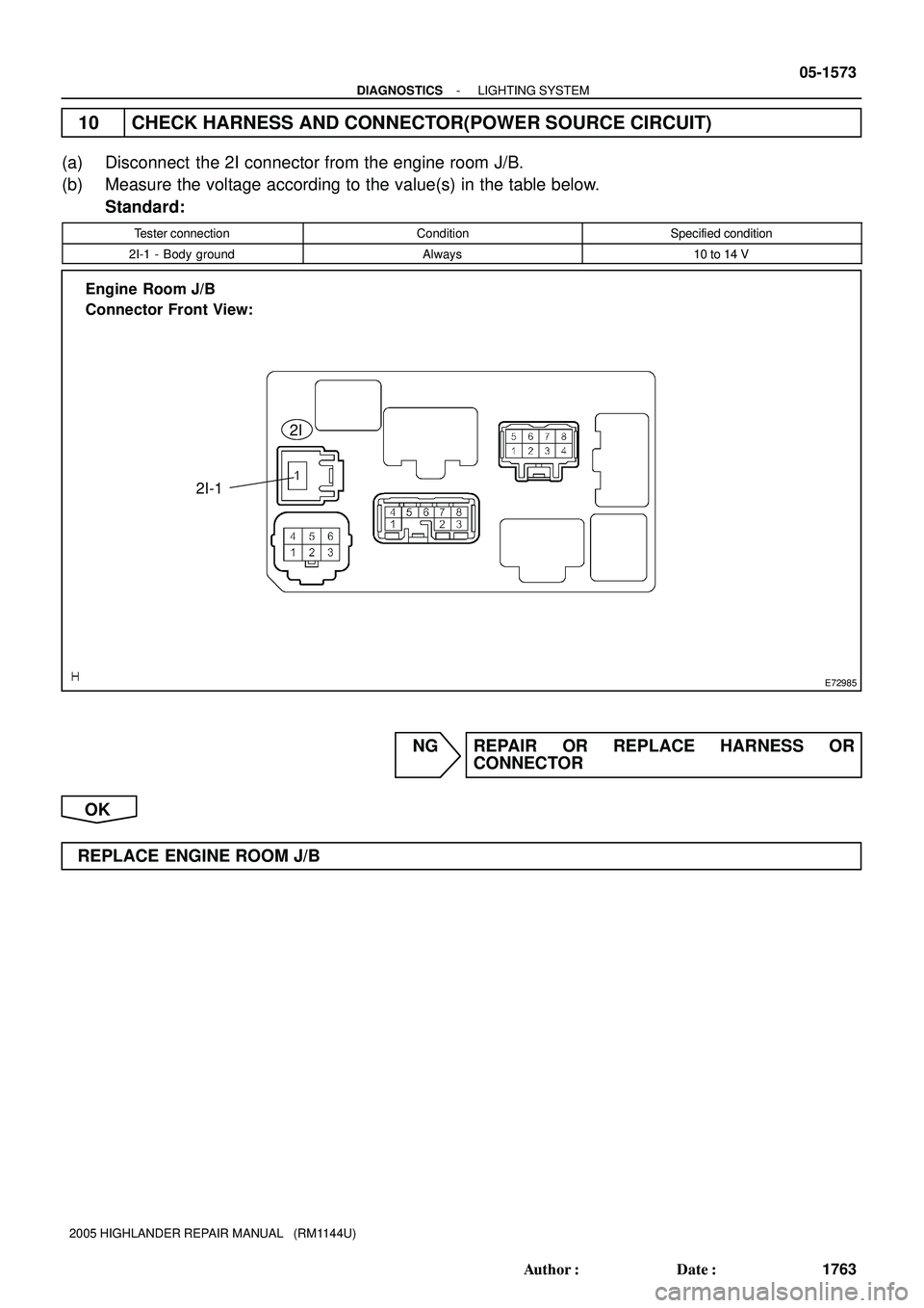
Engine Room J/B
Connector Front View:
2I
2I-1
- DIAGNOSTICSLIGHTING SYSTEM
05-1573
1763 Author�: Date�:
2005 HIGHLANDER REPAIR MANUAL (RM1144U)
10 CHECK HARNESS AND CONNECTOR(POWER SOURCE CIRCUIT)
(a) Disconnect the 2I connector from the engine room J/B.
(b) Measure the voltage according to the value(s) in the table below.
Standard:
Tester connectionConditionSpecified condition
2I-1 - Body groundAlways10 to 14 V
NG REPAIR OR REPLACE HARNESS OR
CONNECTOR
OK
REPLACE ENGINE ROOM J/B
Page 1361 of 2572
E74382
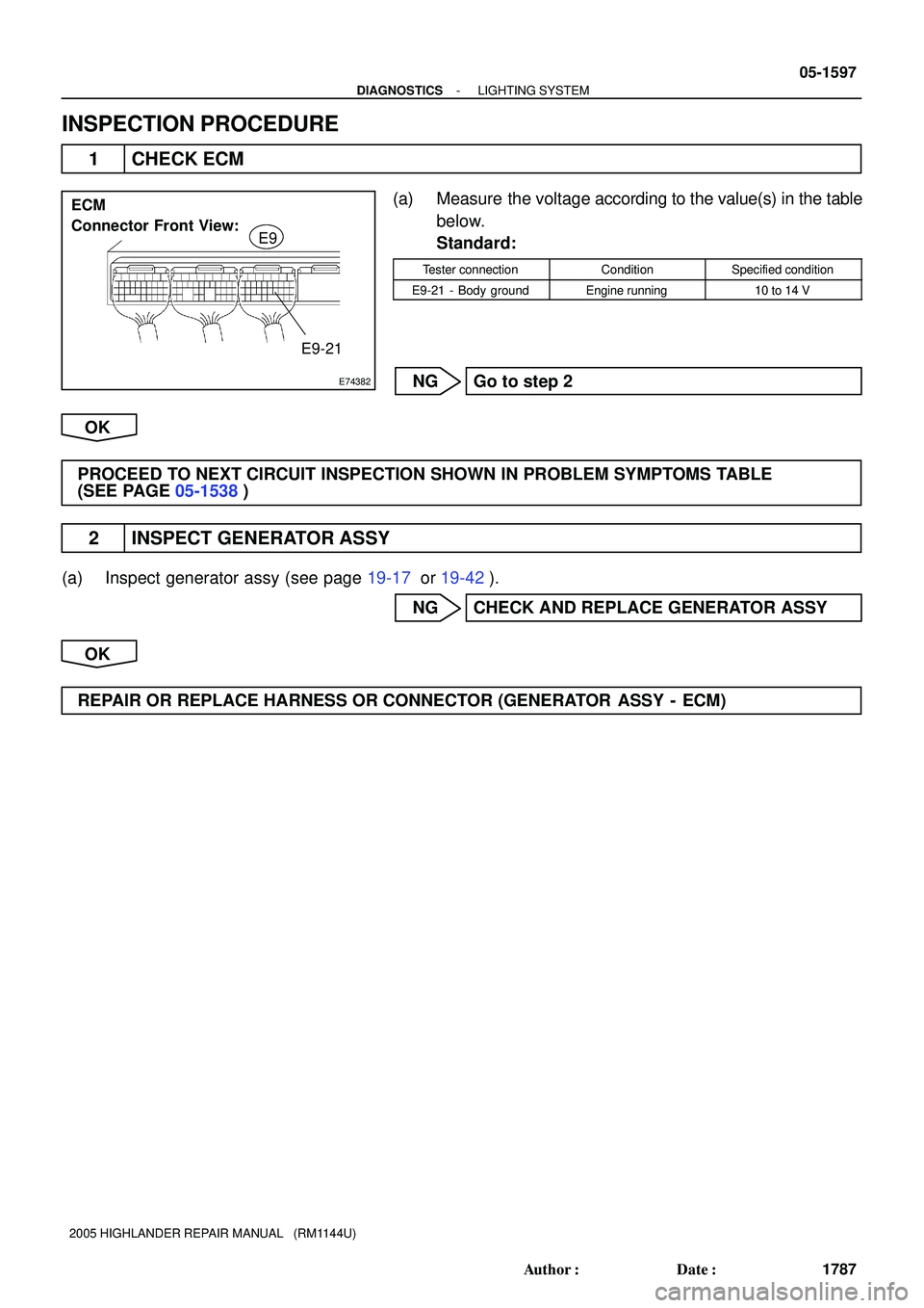
ECM
Connector Front View:
E9
E9-21
- DIAGNOSTICSLIGHTING SYSTEM
05-1597
1787 Author�: Date�:
2005 HIGHLANDER REPAIR MANUAL (RM1144U)
INSPECTION PROCEDURE
1 CHECK ECM
(a) Measure the voltage according to the value(s) in the table
below.
Standard:
Tester connectionConditionSpecified condition
E9-21 - Body groundEngine running10 to 14 V
NG Go to step 2
OK
PROCEED TO NEXT CIRCUIT INSPECTION SHOWN IN PROBLEM SYMPTOMS TABLE
(SEE PAGE 05-1538)
2 INSPECT GENERATOR ASSY
(a) Inspect generator assy (see page 19-17 or 19-42).
NG CHECK AND REPLACE GENERATOR ASSY
OK
REPAIR OR REPLACE HARNESS OR CONNECTOR (GENERATOR ASSY - ECM)
Page 1386 of 2572

DIAGNOSTIC START-UP/FINISH
HINT:
�Illustrations may differ from the")
05ISA-02
I40190
I38204
I38205
05-1784
- DIAGNOSTICSNAVIGATION SYSTEM
1974 Author�: Date�:
2005 HIGHLANDER REPAIR MANUAL (RM1144U)
DIAGNOSTIC START-UP/FINISH
HINT:
�Illustrations may differ from the actual vehicle depending on the device settings and options. There-
fore, some detailed areas may not be shown exactly the same as on the actual vehicle.
�After the ignition switch is turned on, check that the map is displayed before starting the diagnostic
mode. Otherwise, some items cannot be checked.
1. There are 2 methods to start diagnostic mode. Start the mode by using one of them.
2. Method 1
(a) Start the engine.
(b) While pressing and holding ºINFOº switch, operate light
control switch, OFF " TAIL " OFF " TAIL " OFF "
TAIL " OFF.
(c) The diagnostic mode starts and the service check screen
(ºSystem Check Modeº) will be displayed. Service inspec-
tion starts automatically and the result will be displayed.
3. Method 2
(a) Start the engine.
(b) Switch to the ºDisplay Checkº screen.
(c) From the display adjustment screen, touch the corners of
the screen in the following order: upper left " lower left
"upper left " lower left " upper left " lower left.
(d) The diagnostic mode starts and ºService Checkº screen
will be displayed. Service inspection starts automatically
and the result will be displayed.
4. Diagnosis MENU
(a) Diagnostic screen will be displayed by pressing the menu
switch on the service check screen.
Page 1393 of 2572
(From August, 2004)
05-45
235 Author�: Date�:
Hand-held Tester DisplayDiagnostic Note Normal Condition* Measurement Item/Range
(Display)
AF FT B1 S1
Short term fuel tri")
- DIAGNOSTICSSFI SYSTEM (2AZ-FE)(From August, 2004)
05-45
235 Author�: Date�:
Hand-held Tester DisplayDiagnostic Note Normal Condition* Measurement Item/Range
(Display)
AF FT B1 S1
Short term fuel trim associated with bank
1, sensor 1/
Minimum: 0, Maximum: 1.999
�Value less than 1 (0.000 to
0.999) = LEAN
�Stoichiometric Air-Fuel Ratio=1
�Value greater than 1 (1.001 to
1.999) = RICH
-
FUEL SYS #1
Fuel system status (Bank 1) /
OL or CL or OL DRIVE or
OL FAULT or CL FAULT
Idling after warming up: CL
�OL (Open Loop) : Has not yet sa-
tisfied conditions to go closed
loop
�CL (Closed Loop) : Using heated
oxygen sensor(s) as feed back
for fuel control
�OL DRIVE: Open loop due to
driving conditions (fuel enrich-
ment)
�OL FAULT: Open loop due to de-
tected system fault
�CL FAULT: Closed loop but one
of heated oxygen sensors, which
is used for fuel control, is mal-
functioning
FC IDLIdle fuel cut/ ON or OFFFuel cut operation: ON
FC IDL = ON when throttle valve
is fully closed and engine speed is
over 1,500 rpm
MILMIL status/ ON or OFFMIL ON: ON-
STARTER SIGStarter signal/ ON or OFFCranking: ON-
A/C SIGA/C signal/ ON or OFFA/C ON: ON-
PNP SW [NSW]PNP switch signal/ ON or OFFP or N position: ON-
ELECT LOAD SIGElectrical load signal/ ON or OFFDefogger switch ON: ON-
STOP LIGHT SWStop lamp switch/ ON or OFF�Brake pedal depressed: ON
�Brake pedal released: OFF-
PS OIL PRESS SWPower steering signal/ ON or OFF
�While turning steering wheel: ON
�While not turning steering wheel:
OFFIdle-up control is performed when
PS is ON
PS SIGNALPower steering signal/
ON or OFFWhen steering wheel is turnedThis signal is usually ON until Igni-
tion switch is turned OFF
FUEL PUMP / SPDFuel pump / speed status /
ON/H or OFF/M,LIdling: ON-
A/C MAG CLUTCHA/C magnet clutch status /
ON or OFFA/C magnet clutch ON: ON-
EVAP VSVEVAP VSV status control /
ON or OFFVSV operating: ONEVAP VSV is controlled by ECM
(ground side duty control)
VVT CTRL B1VVT control status (Bank 1) /
ON or OFFVVT system operation: ON-
IGNITIONIgnition counter/ Minimum: 0,
Maximum: 4000 to 400-
CYL #1, #2, #3, #4Misfire ratio of cylinder 1 to 4/
Minimum: 0 %, Maximum: 50 %0 %This item is displayed in only idling
MISFIRE LOADEngine load for first misfire range/
Minimum: 0 g/rev, Maximum: 3.98 g/rev.Misfire 0: 0 g/rev.'
MISFIRE RPMEngine RPM for first misfire range/
Minimum: 0 rpm, Maximum: 6,375 rpmMisfire 0: 0 rpm'
FC TAUFuel Cut TAU: Fuel cut during very light
load/ ON or OFFFuel cut operating: ON
Fuel cut is being performed under
very light load to prevent engine
combustion from becoming incom-
plete
CHECK MODECheck mode/ ON or OFFCheck mode ON: ONSee page 05-40
Page 1400 of 2572
(From August, 2004)
600 Author�: Date�:
Hand-held Tester DisplayDiagnostic Note Normal Condition * Measurement Item/Range
(Display)
EVAP VSVVSV status for EVAP c")
05-410
- DIAGNOSTICSSFI SYSTEM (3MZ-FE)(From August, 2004)
600 Author�: Date�:
Hand-held Tester DisplayDiagnostic Note Normal Condition * Measurement Item/Range
(Display)
EVAP VSVVSV status for EVAP control/
ON or OFFVSV operating: ONEVAP VSV is controlled by the
ECM (ground side duty control)
BOOST PRESS VSV
VSV status for boost pressure
control/
ON or OFF
VSV operating: ON'
IGNITIONIgnition counter/ Minimum: 0, Max-
imum: 6000 to 600'
CYL #1, #2, #3, #4, #5, #6Misfire ratio of cylinder 1 to 6/
Minimum: 0 %, Maximum: 50 %0 %This item is displayed in only idling
MISFIRE LOAD
Engine load for first misfire range/
Minimum: 0 g/rev, Maximum: 3.98
g/rev.
Misfire 0: 0 g/rev.'
MISFIRE RPM
Engine RPM for first misfire range/
Minimum: 0 rpm, Maximum: 6,375
rpm
Misfire 0: 0 rpm'
FC TAUFuel Cut TAU: Fuel cut during very
light load/ ON or OFFFuel cut operating: ON
Fuel cut is being performed under
very light load to prevent engine
combustion from becoming incom-
plete
CHECK MODECheck mode/ ON or OFFCheck mode ON: ONSee step 3
HINT:
*: If no conditions are specifically stated for ºldlingº, the shift lever is in the N or P position, the A/C switch
is OFF and all accessory switches are OFF.
2. ACTIVE TEST
HINT:
Performing the hand-held tester ACTIVE TEST allows relay, VSV, actuator and other items to be operated
without removing any parts. Performing the ACTIVE TEST early in troubleshooting is one way to shorten
labor time. The DATA LIST can be displayed during the ACTIVE TEST.
(a) Warm up the engine.
(b) Turn the ignition switch OFF.
(c) Connect the hand-held tester or the OBD II scan tool to the DLC3.
(d) Turn the ignition switch ON.
(e) Turn ON the hand-held tester or the OBD II scan tool.
(f) Enter the following menus: DIAGNOSIS / ENHANCED OBD II / ACTIVE TEST.
(g) According to the display on tester, perform the ºACTIVE TESTº.
Hand-held Tester DisplayTest DetailsDiagnostic Note
INJ VOL
[Test Details]
Control injection volume
Minimum: -12.5 %, Maximum: 25 %
[Vehicle Condition]
Engine speed: 3,000 rpm or less�All injectors are tested at once
�Injection volume is gradually
changed between -12.5 and 25
%
A/F CONTROL
[Test Details]
Control injection volume
-12.5 or 25 % (change injection volume -12.5 % or 25 %)
[Vehicle Condition]
Engine speed: 3,000 rpm or less
Following A/F CONTROL proce-
dure enables technician to check
and graph voltage outputs of both
the A/F sensor and heated oxygen
sensor
For displaying graph, enter ºAC-
TIVE TEST / A/F CONTROL /
USER DATAº, select ºAFS B1S1
and O2S B1S2º by pressing ºYESº
and push ºENTERº. Then press
ºF4º
Page 1508 of 2572
E74263
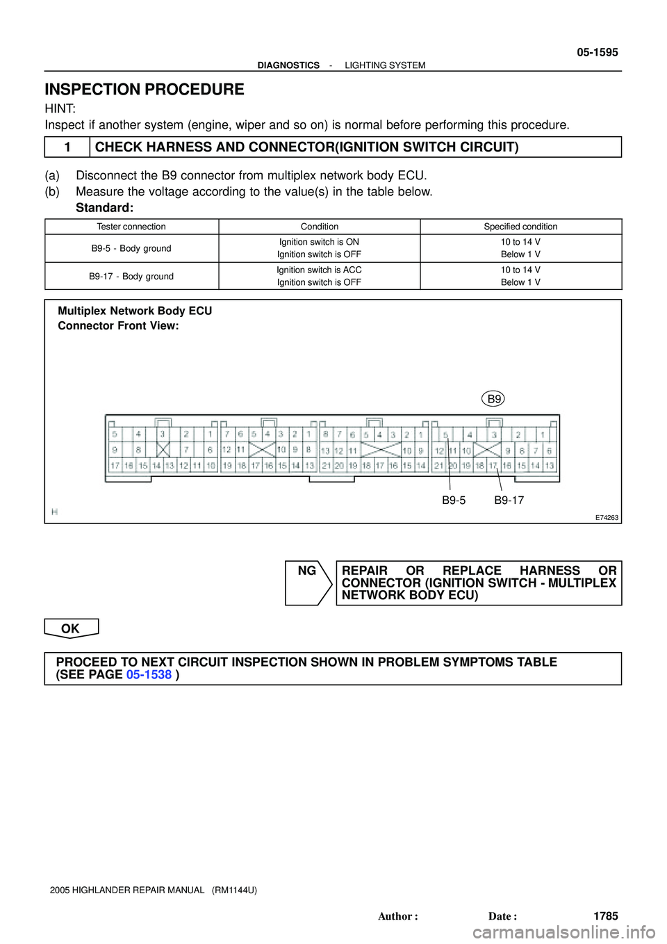
Multiplex Network Body ECU
Connector Front View:
B9
B9-5B9-17
- DIAGNOSTICSLIGHTING SYSTEM
05-1595
1785 Author�: Date�:
2005 HIGHLANDER REPAIR MANUAL (RM1144U)
INSPECTION PROCEDURE
HINT:
Inspect if another system (engine, wiper and so on) is normal before performing this procedure.
1 CHECK HARNESS AND CONNECTOR(IGNITION SWITCH CIRCUIT)
(a) Disconnect the B9 connector from multiplex network body ECU.
(b) Measure the voltage according to the value(s) in the table below.
Standard:
Tester connectionConditionSpecified condition
B9-5 - Body groundIgnition switch is ON
Ignition switch is OFF10 to 14 V
Below 1 V
B9-17 - Body groundIgnition switch is ACC
Ignition switch is OFF10 to 14 V
Below 1 V
NG REPAIR OR REPLACE HARNESS OR
CONNECTOR (IGNITION SWITCH - MULTIPLEX
NETWORK BODY ECU)
OK
PROCEED TO NEXT CIRCUIT INSPECTION SHOWN IN PROBLEM SYMPTOMS TABLE
(SEE PAGE 05-1538)
Page 1536 of 2572
E72974
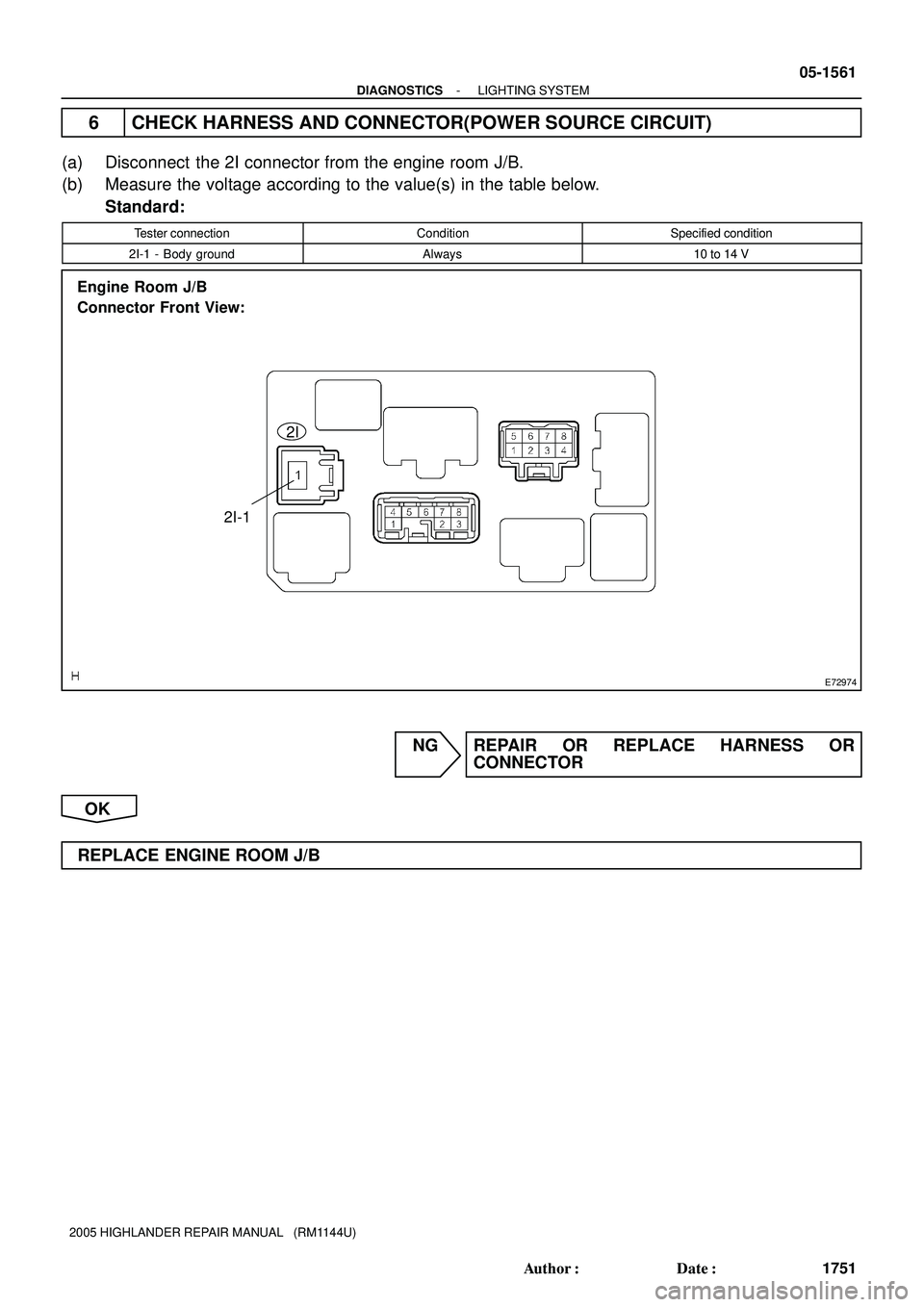
2I
2I-1 Engine Room J/B
Connector Front View:
- DIAGNOSTICSLIGHTING SYSTEM
05-1561
1751 Author�: Date�:
2005 HIGHLANDER REPAIR MANUAL (RM1144U)
6 CHECK HARNESS AND CONNECTOR(POWER SOURCE CIRCUIT)
(a) Disconnect the 2I connector from the engine room J/B.
(b) Measure the voltage according to the value(s) in the table below.
Standard:
Tester connectionConditionSpecified condition
2I-1 - Body groundAlways10 to 14 V
NG REPAIR OR REPLACE HARNESS OR
CONNECTOR
OK
REPLACE ENGINE ROOM J/B
Page 1607 of 2572

NOISE OCCURS
INSPECTION PROCEDURE
1 CHECK OF SPEAKER INSTALLATION
(a) Check the speaker installation co")
05-1674
- DIAGNOSTICSAUDIO SYSTEM
1864 Author�: Date�:
2005 HIGHLANDER REPAIR MANUAL (RM1144U)
NOISE OCCURS
INSPECTION PROCEDURE
1 CHECK OF SPEAKER INSTALLATION
(a) Check the speaker installation condition.
(1) Check that each speaker is securely installed.
OK: Malfunction disappears.
HINT:
The radio is equipped with a noise prevention system that blocks only excessively loud noise. If loud noise
occurs, check whether or not the ground on the antenna installation part and the proper noise-prevention
equipment are all installed, and whether or not there is improper wiring.
Condition in which noise occursNoise type
Depressing the acceleration pedal increases the noise, and stopping the
engine stops the noise immediately.Alternator noise
Noise occurs during A/C or the heater operation.Blower motor noise
Rapid acceleration during the drive on an unpaved road or after the ignition
switch is turned on makes noise.Fuel pump noise
Pressing and then releasing the horn switch, and keeping pressing the horn
switch makes noise.Horn noise
Quiet noise is heard while the engine is running, but stops with the engine.Ignition noise
Noise occurs in turn with the blink of the turn signal flash.Flasher noise
Noise occurs during window washer operation.Washer noise
Noise occurs while the engine is running, and it continues even after the en-
gine is stopped.Water temperature sensor noise
Noise occurs during wiper operation.Wiper noise
Noise occurs when the brake pedal is depressed.Stop light switch noise
OthersStatic electricity on the vehicle
HINT:
�Identify the condition in which the noise occurs, and check the noise filter on the related part.
�Make sure first that there is no noise from outside. Failing to do so makes the noise occurrence source
detection difficult and leads to misdiagnosis.
�The noise should be removed in descending order of loudness.
NG INSTALL IT PROPERLY
OK
IDENTIFICATION OF NOISE SOURCE
055M1-10