Page 583 of 1897

CO09I-02
Z00570
Radiator Cap Tester
30° or More
Radiator Cap
P13014
Radiator Cap
Tester CO-14
- COOLINGRADIATOR
1207 Author�: Date�:
2001 AVALON (RM808U)
ON-VEHICLE INSPECTION
1. REMOVE RADIATOR CAP
CAUTION:
To avoid the danger of being burned, do not remove the ra-
diator cap while the engine and radiator are still hot, as fluid
and steam can be blow out under pressure.
2. INSPECT RADIATOR CAP
NOTICE:
�If the radiator cap has contaminations, always rinse
it with water.
�When performing steps (a) and (b) below, keep the ra-
diator cap tester at an angle of over 30° above the hor-
izontal.
�Before using a radiator cap tester, wet the relief valve
and pressure valve with engine coolant or water.
(a) Using a radiator cap tester, slowly pump the tester and
check that air is coming from the vacuum valve.
Pump speed: 1 push/(3 seconds or more)
NOTICE:
Push the pump at a constant speed.
If air is not coming from the vacuum valve, replace the radiator
cap.
(b) Pump the tester and measure the relief valve opening
pressure.
Pump speed: 1 push within 1 second
NOTICE:
This pump speed is for the first pump only (in order to close
the vacuum valve). After this, the pump speed can be re-
duced.
Standard opening pressure:
83 - 113 kPa (0.85 - 1.15 kgf/cm
2, 12.1 - 16.4 psi)
Minimum opening pressure:
69 kPa (0.7 kgf/cm
2, 10.0 psi)
HINT:
Use the tester's maximum reading as the opening pressure.
If the opening pressure is less than minimum, replace the radia-
tor cap.
3. INSPECT COOLING SYSTEM FOR LEAKS
(a) Fill the radiator with coolant, and attach a radiator cap tes-
ter.
(b) Warm up the engine.
(c) Pump it to 127 kPa (1.3 kgf/cm
2, 18.5 psi), and check that
the pressure does not drop.
If the pressure drops, check the hoses, radiator or water pump
for leaks. If no external leaks are found, check the heater core,
cylinder block and cylinder head.
4. REINSTALL RADIATOR CAP
Page 590 of 1897
CO02T-03
B04153Stud BoltJiggle Valve
15°15°
CO-12
- COOLINGTHERMOSTAT
1205 Author�: Date�:
2001 AVALON (RM808U)
INSTALLATION
1. PLACE THERMOSTAT IN WATER PUMP
(a) Install a new gasket on to the thermostat.
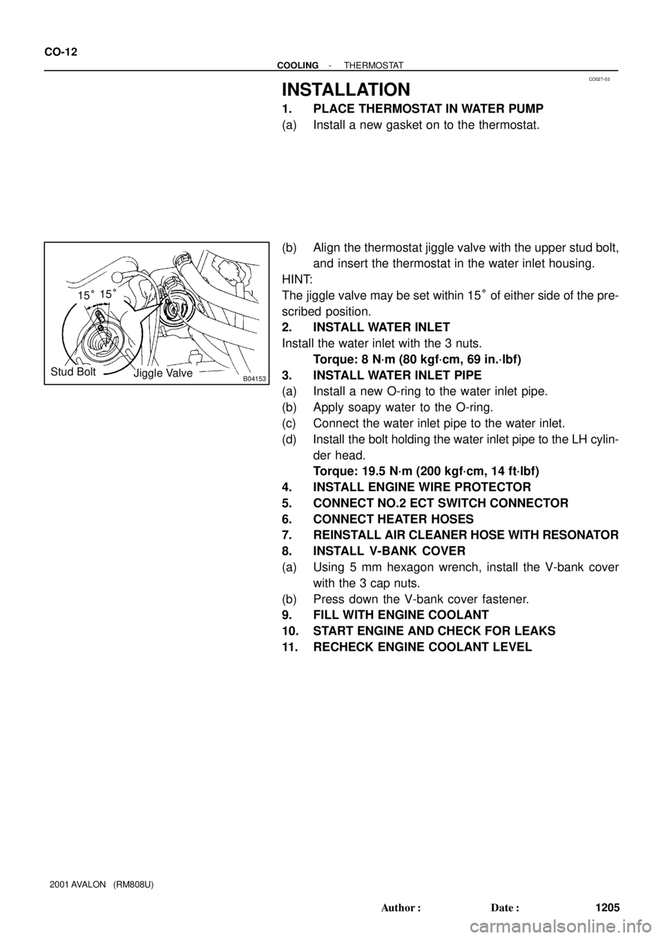
(b) Align the thermostat jiggle valve with the upper stud bolt,
and insert the thermostat in the water inlet housing.
HINT:
The jiggle valve may be set within 15° of either side of the pre-
scribed position.
2. INSTALL WATER INLET
Install the water inlet with the 3 nuts.
Torque: 8 N´m (80 kgf´cm, 69 in.´lbf)
3. INSTALL WATER INLET PIPE
(a) Install a new O-ring to the water inlet pipe.
(b) Apply soapy water to the O-ring.
(c) Connect the water inlet pipe to the water inlet.
(d) Install the bolt holding the water inlet pipe to the LH cylin-
der head.
Torque: 19.5 N´m (200 kgf´cm, 14 ft´lbf)
4. INSTALL ENGINE WIRE PROTECTOR
5. CONNECT NO.2 ECT SWITCH CONNECTOR
6. CONNECT HEATER HOSES
7. REINSTALL AIR CLEANER HOSE WITH RESONATOR
8. INSTALL V-BANK COVER
(a) Using 5 mm hexagon wrench, install the V-bank cover
with the 3 cap nuts.
(b) Press down the V-bank cover fastener.
9. FILL WITH ENGINE COOLANT
10. START ENGINE AND CHECK FOR LEAKS
11. RECHECK ENGINE COOLANT LEVEL
Page 592 of 1897
CO02M-03
A10834
RH Fender Apron Seal
Generator Drive Belt
Engine Moving
Control Rod
No.2 RH Engine
Mounting Bracket
Ground Strap
Connector PS Pump Drive Belt
Engine Coolant Reservoir Hose
: Specified torque
64 (650, 47)
32 (320, 23)
N´m (kgf´cm, ft´lbf)
- COOLINGWATER PUMP
CO-3
1196 Author�: Date�:
2001 AVALON (RM808U)
WATER PUMP
COMPONENTS
Page 593 of 1897
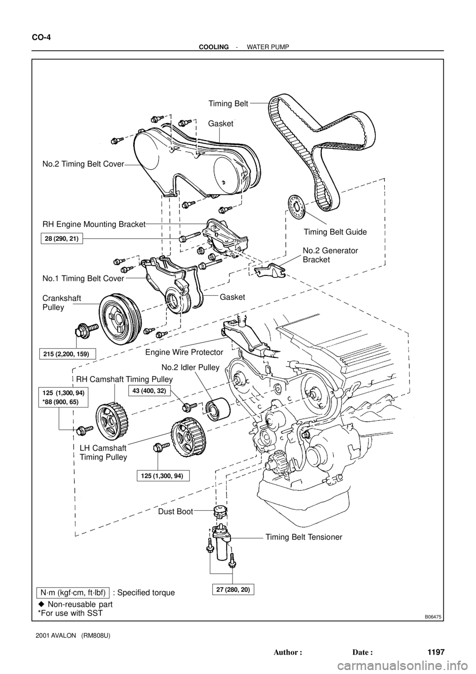
B06475
No.2 Timing Belt CoverTiming Belt
Gasket
Timing Belt Guide
No.2 Generator
Bracket RH Engine Mounting Bracket
28 (290, 21)
Crankshaft
Pulley
215 (2,200, 159)
Gasket
Engine Wire Protector
125 (1,300, 94)
*88 (900, 65)
RH Camshaft Timing Pulley
43 (400, 32)
No.2 Idler Pulley
125 (1,300, 94)
Dust Boot
Timing Belt Tensioner
27 (280, 20)
� Non-reusable part
*For use with SSTNo.1 Timing Belt Cover
LH Camshaft
Timing Pulley
N´m (kgf´cm, ft´lbf) : Specified torque
CO-4
- COOLINGWATER PUMP
1197 Author�: Date�:
2001 AVALON (RM808U)
Page 594 of 1897
B06476� Non-reusable partNo.3 Timing Belt CoverGasket
Collar
Bushing
Water Pump� Gasket Engine Wire
8.5 (65, 74 in.´lbf)
x 6
8 (80, 69 in.´lbf)
N´m (kgf´cm, ft´lbf) : Specified torque
- COOLINGWATER PUMP
CO-5
1198 Author�: Date�:
2001 AVALON (RM808U)
Page 595 of 1897
CO02O-03
P12487
- COOLINGWATER PUMP
CO-7
1200 Author�: Date�:
2001 AVALON (RM808U)
INSPECTION
1. INSPECT WATER PUMP
(a) Visually check the drain hole for coolant leakage.
If leakage is found, replace the water pump.
(b) Turn the pulley, and check that the water pump bearing
moves smoothly and quietly.
If necessary, replace the water pump.
2. INSPECT TIMING BELT COMPONENTS
(See page EM-19)
Page 596 of 1897
CO02P-03
P12942
CO-8
- COOLINGWATER PUMP
1201 Author�: Date�:
2001 AVALON (RM808U)
INSTALLATION
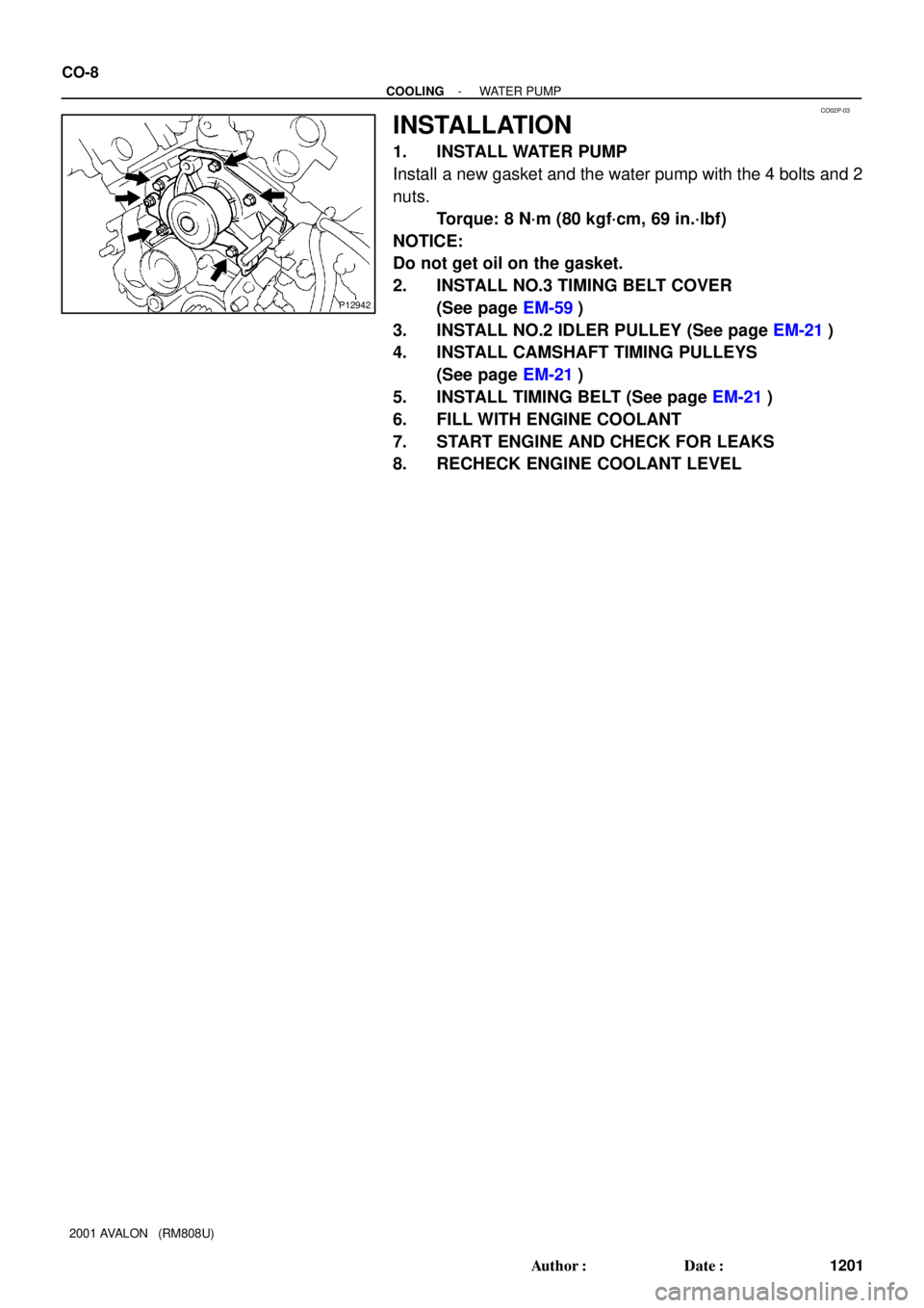
1. INSTALL WATER PUMP
Install a new gasket and the water pump with the 4 bolts and 2
nuts.
Torque: 8 N´m (80 kgf´cm, 69 in.´lbf)
NOTICE:
Do not get oil on the gasket.
2. INSTALL NO.3 TIMING BELT COVER
(See page EM-59)
3. INSTALL NO.2 IDLER PULLEY (See page EM-21)
4. INSTALL CAMSHAFT TIMING PULLEYS
(See page EM-21)
5. INSTALL TIMING BELT (See page EM-21)
6. FILL WITH ENGINE COOLANT
7. START ENGINE AND CHECK FOR LEAKS
8. RECHECK ENGINE COOLANT LEVEL
Page 597 of 1897
CO0WS-01
P12942
CO-6
- COOLINGWATER PUMP
1199 Author�: Date�:
2001 AVALON (RM808U)
REMOVAL
1. DRAIN ENGINE COOLANT
2. REMOVE TIMING BELT (See page EM-15)
3. REMOVE CAMSHAFT TIMING PULLEYS
(See page EM-15)
4. REMOVE NO.2 IDLER PULLEY (See page EM-31)
5. REMOVE NO.3 TIMING BELT COVER
(See page EM-15)
6. REMOVE WATER PUMP
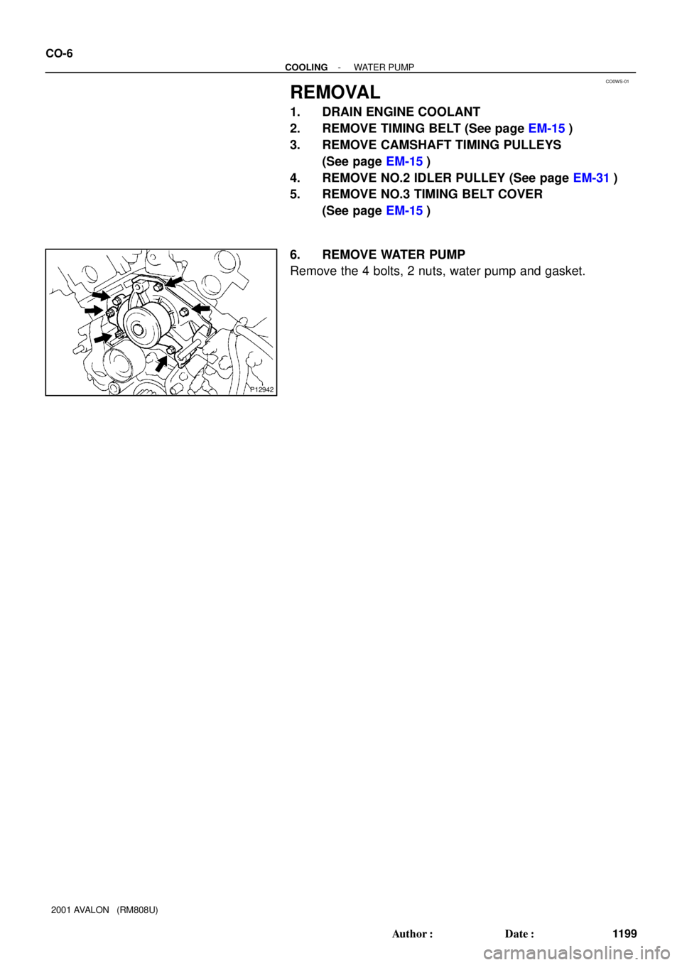
Remove the 4 bolts, 2 nuts, water pump and gasket.