Page 1634 of 1897

Battery
B06482
SF-24
- SFIINJECTOR
1133 Author�: Date�:
2001 AVALON (RM808U)
(j) If you have no TOYOTA hand-held tester, connect the
positive (+) and negative (-) leads from the")
B06483
SST
(Wire)
Battery
B06482
SF-24
- SFIINJECTOR
1133 Author�: Date�:
2001 AVALON (RM808U)
(j) If you have no TOYOTA hand-held tester, connect the
positive (+) and negative (-) leads from the battery to the
fuel pump connector (See page SF-6).
(k) Connect SST (wire) to the injector and battery for 15 se-
conds, and measure the injection volume with a gra-
duated cylinder. Test each injector 2 or 3 times.
SST 09842-30070
Volume: 60 - 73 cm
3 (3.4 - 4.5 cu in.) per 15 sec.
Difference between each injector:
13 cm
3 (0.8 cu in.) or less
If the injection volume is not as specified, replace the injector.
2. INSPECT LEAKAGE
(a) In the condition above, disconnect the test probes of SST
(wire) from the battery and check the fuel leakage from
the injector.
SST 09842-30070
Fuel drop: 1 drop or less per 12 minutes
(b) Turn the ignition switch OFF.
(c) Disconnect the negative (-) terminal cable from the bat-
tery.
(d) Remove the SST and fuel tube connector.
SST 09268-41047, 09842-30070
CAUTION:
�Perform disconnecting operations of the fuel tube
connector (quick type) after observing the precau-
tions (See page SF-1).
�As there is retained pressure in the fuel pipe line, pre-
vent it from splashing inside the engine compart-
ment.
(e) Disconnect the TOYOTA hand- held tester from the
DLC3.
Page 1636 of 1897

(m) Tighten the 4 bolts holding the delivery pipes to the intake
manifold.
Torq")
B01020
B06618
Align
B09079
B09076
Fuel Hose
Clamp
B06613
SF-26
- SFIINJECTOR
1135 Author�: Date�:
2001 AVALON (RM808U)
(m) Tighten the 4 bolts holding the delivery pipes to the intake
manifold.
Torque: 10 N´m (100 kgf´cm, 7 ft´lbf)
(n) Tighten the bolt holding the No.1 fuel pipe to the intake
manifold.
Torque: 19.5 N´m (200 kgf´cm, 14 ft´lbf)
2. CONNECT NO.1 FUEL PIPE
(a) Align the alignment marks (white paint) on the No.1 fuel
pipe.
(b) Connect the No.1 fuel pipe (fuel tube connector) to the
fuel filter.
CAUTION:
Perform connecting operations of the fuel tube connector
(quick type) after observing the precautions.
(c) Surely install the fuel hose clamp to the fuel filter with
ºclickº sound.
(d) After installing the clamp, check that the clamp is fixed by
pulling up the clamp.
3. INSTALL AIR ASSIST HOSES AND PIPE
4. CONNECT INJECTOR CONNECTORS
5. INSTALL AIR INTAKE CHAMBER ASSEMBLY
(See page EM-59)
6. INSTALL AIR CLEANER HOSE WITH RESONATOR
7. INSTALL V-BANK COVER
(a) Using 5 mm hexagon wrench, install the V-bank cover
with the 3 cap nuts.
(b) Press down the V-bank cover fastener.
8. CHECK FOR FUEL LEAKS
Page 1638 of 1897
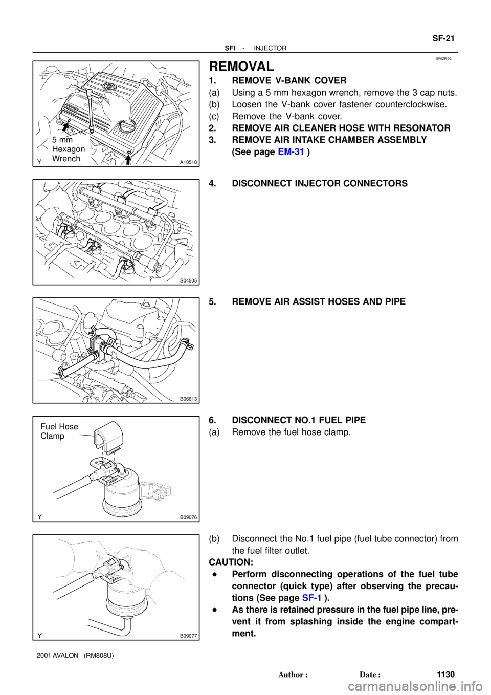
SF0ZR-02
A10518
5 mm
Hexagon
Wrench
S04505
B06613
B09076
Fuel Hose
Clamp
B09077
- SFIINJECTOR
SF-21
1130 Author�: Date�:
2001 AVALON (RM808U)
REMOVAL
1. REMOVE V-BANK COVER
(a) Using a 5 mm hexagon wrench, remove the 3 cap nuts.
(b) Loosen the V-bank cover fastener counterclockwise.
(c) Remove the V-bank cover.
2. REMOVE AIR CLEANER HOSE WITH RESONATOR
3. REMOVE AIR INTAKE CHAMBER ASSEMBLY
(See page EM-31)
4. DISCONNECT INJECTOR CONNECTORS
5. REMOVE AIR ASSIST HOSES AND PIPE
6. DISCONNECT NO.1 FUEL PIPE
(a) Remove the fuel hose clamp.
(b) Disconnect the No.1 fuel pipe (fuel tube connector) from
the fuel filter outlet.
CAUTION:
�Perform disconnecting operations of the fuel tube
connector (quick type) after observing the precau-
tions (See page SF-1).
�As there is retained pressure in the fuel pipe line, pre-
vent it from splashing inside the engine compart-
ment.
Page 1648 of 1897

S05054
New Gasket
FI1654
Fulcrum Length
30 cm
SST
FI6372
CORRECT New O-Ring
Delivery Pipe
Injector Grommet
WRONG
B05295
O-Ring
Grommet
Spacer InsulatorDelivery Pipe
O-Ring
- SFISFI SYSTEM
SF-3
111 2 Author�: Date�:
2001 AVALON (RM808U)
(b) When connecting the union bolt on the high pressure pipe
union, observe the following procedures:
(1) Always use 2 new gaskets.
(2) Tighten the union bolt by hand.
(3) Tighten the union bolt to the specified torque.
Torque: 29 N´m (300 kgf´cm, 21 ft´lbf)
(c) When connecting the flare nut on the high pressure pipe
union, observe the following procedures:
(1) Apply a light coat of engine oil to the flare nut, and
tighten the flare nut by hand.
(2) Using SST, tighten the flare nut to specified torque.
SST 09023-12700
NOTICE:
Do not rotate the fuel pipe, when tightening the flare nut.
Torque: 28 N´m (285 kgf´cm, 21 ft´lbf)
HINT:
Use a torque wrench with a fulcrum length of 30 cm (11.81 in.).
(d) Observe the following precautions when removing and
installing the injectors.
(1) Never reuse the O-ring.
(2) When placing a new O-ring on the injector, take
care not to damage it in any way.
(3) Coat a new O-ring with spindle oil or gasoline be-
fore installing-never use engine, gear or brake oil.
(e) Install the injector to the delivery pipe and intake manifold
as shown in the illustration.
(f) Observe these precautions when disconnecting the fuel
tube connector (quick type).
(1) Check if there is any dirt like mud on the pipe and
around the connector before disconnecting them
and clean the dirt away.
(2) Be sure to disconnect with hands.
Page 1649 of 1897

(3) When the connector and the pipe are stuck, pinch
the retainer between t")
S04583
S05040
Vinyl Bag
S05382
Retainer
S05050
Click Sound SF-4
- SFISFI SYSTEM
111 3 Author�: Date�:
2001 AVALON (RM808U)
(3) When the connector and the pipe are stuck, pinch
the retainer between the hands, push and pull the
connector to free to disconnect and pull it out. Do
not use any tool at this time.
(4) Inspect if there is any dirt or the likes on the seal sur-
face of the disconnected pipe and clean it away.
(5) Prevent the disconnected pipe and connector from
damaging and mixing foreign objects by covering
them with a vinyl bag.
(g) Observe these precautions when connecting the fuel
tube connector (quick type).
(1) Do not reuse the retainer removed from the pipe.
(2) Must use hands without using tools when to remove
the retainer from the pipe.
(3) Check if there is any damage or foreign objects on
the connected part of the pipe.
(4) Match the axis of the connector with axis of the pipe,
and push in the connector until the retainer makes
a ºclickº sound. In case that the connections is tight,
apply little amount of new engine oil on the tip of the
pipe.
(5) After having finished the connection, check if the
pipe and the connector are securely connected by
pulling them.
(6) Check if there is any fuel leakage.
(h) Observe these precautions when handling nylon tube.
(1) Pay attention not to turn the connector with force
when connecting them.
(2) Pay attention not to kink the nylon tube.
(3) Do not remove the EPDM protector on the outside
of the nylon tube.
(4) Must not close the piping with the nylon tube by
bending it.
Before installing the injector, must apply spindle oil
or gasoline on the place where a delivery pipe or an
intake manifold touches an O-ring of the injector.
Page 1670 of 1897
SF101-02
B08628
Charcoal CanisterVapor Pressure Sensor
(Type A)Vapor Pressure Sensor
(Type B)
Vapor Pressure Sensor
Connector
Vacuum Hose
Fuel Hose
Vacuum Hose SF-74
- SFIVAPOR PRESSURE SENSOR
1183 Author�: Date�:
2001 AVALON (RM808U)
VAPOR PRESSURE SENSOR
COMPONENTS
Page 1671 of 1897

SF06R-03
B08629
Disconnect
VC
E2Voltmeter
B08630
Type B
VacuumVacuum
PTNK E2 ECM Type A
Disconnect
DisconnectPressure
Pressure
- SFIVAPOR PRESSURE SENSOR
SF-75
1184 Author�: Date�:
2001 AVALON (RM808U)
INSPECTION
1. INSPECT POWER SOURCE VOLTAGE OF VAPOR
PRESSURE SENSOR
(a) Disconnect the vapor pressure sensor connector.
(b) Turn the ignition switch ON.
(c) Using a voltmeter, measure the voltage between connec-
tor terminals VC and E2 of the wiring harness side.
Voltage: 4.5 - 5.5 V
(d) Turn the ignition switch OFF.
(e) Reconnect the vapor pressure sensor connector.
2. INSPECT POWER OUTPUT OF VAPOR PRESSURE
SENSOR
(a) Turn the ignition switch ON.
(b) Disconnect the fuel hose from the vapor pressure sensor.
(c) Connect a voltmeter to terminals PTNK and E2 of the
ECM, and measure the output voltage under the following
conditions:
(1) Apply vacuum (2.0 kPa (15 mmHg, 0.59 in.Hg)) to
the vapor pressure sensor.
Voltage: 1.3 - 2.1 V
(2) Release the vacuum from the vapor pressure sen-
sor.
Voltage: 3.0 - 3.6 V
(3) Apply pressure (1.5 kPa (15 gf/cm
2, 0.22 psi)) to the
vapor pressure sensor.
Voltage: 4.2 - 4.8 V
(d) Turn the ignition switch OFF.
(e) Reconnect the fuel hose to the vapor pressure sensor.
Page:
< prev 1-8 9-16 17-24
Vapor Pressure Sensor
(Type B)
Vapor Pressure Sensor
Connector
Vacuum Hose
Fuel Hose
Vacuum Hose SF-74
- SFIVAPOR PRESSURE SENSOR
1183 Au")