Page 519 of 1897
BR0L1-04
F06984
F06985
BR-26
- BRAKEFRONT BRAKE PAD
1425 Author�: Date�:
2001 AVALON (RM808U)
REPLACEMENT
1. REMOVE FRONT WHEEL
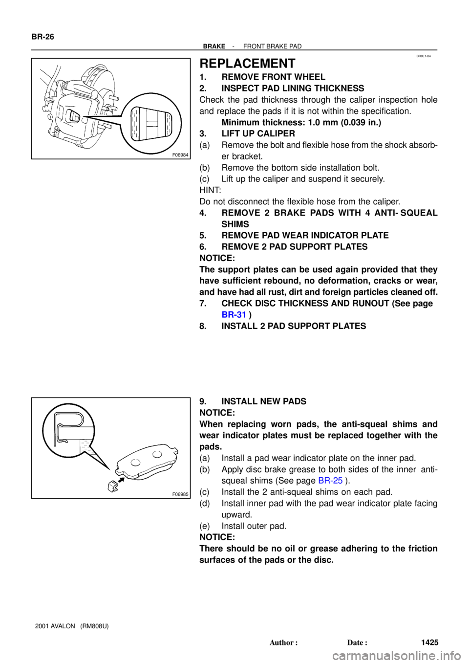
2. INSPECT PAD LINING THICKNESS
Check the pad thickness through the caliper inspection hole
and replace the pads if it is not within the specification.
Minimum thickness: 1.0 mm (0.039 in.)
3. LIFT UP CALIPER
(a) Remove the bolt and flexible hose from the shock absorb-
er bracket.
(b) Remove the bottom side installation bolt.
(c) Lift up the caliper and suspend it securely.
HINT:
Do not disconnect the flexible hose from the caliper.
4. REMOVE 2 BRAKE PADS WITH 4 ANTI- SQUEAL
SHIMS
5. REMOVE PAD WEAR INDICATOR PLATE
6. REMOVE 2 PAD SUPPORT PLATES
NOTICE:
The support plates can be used again provided that they
have sufficient rebound, no deformation, cracks or wear,
and have had all rust, dirt and foreign particles cleaned off.
7. CHECK DISC THICKNESS AND RUNOUT (See page
BR-31)
8. INSTALL 2 PAD SUPPORT PLATES
9. INSTALL NEW PADS
NOTICE:
When replacing worn pads, the anti-squeal shims and
wear indicator plates must be replaced together with the
pads.
(a) Install a pad wear indicator plate on the inner pad.
(b) Apply disc brake grease to both sides of the inner anti-
squeal shims (See page BR-25).
(c) Install the 2 anti-squeal shims on each pad.
(d) Install inner pad with the pad wear indicator plate facing
upward.
(e) Install outer pad.
NOTICE:
There should be no oil or grease adhering to the friction
surfaces of the pads or the disc.
Page 520 of 1897
R02981
- BRAKEFRONT BRAKE PAD
BR-27
1426 Author�: Date�:
2001 AVALON (RM808U)
10. INSTALL CALIPER
(a) Draw out a small amount of brake fluid from the reservoir.
(b) Press in the piston with a hammer handle or similar imple-
ment.
HINT:
If the piston is difficult to push in, loosen the bleeder plug and
push in the piston while letting some brake fluid escape.
(c) Install the caliper.
(d) Hold the sliding pin and torque the installation bolt.
Torque: 34 N´m (350 kgf´cm, 25 ft´lbf)
(e) Install the flexible hose and bolt to the shock absorber
bracket.
Torque: 29 N´m (300 kgf´cm, 21 ft´lbf)
11. INSTALL FRONT WHEEL
Torque: 103 N´m (1,050 kgf´cm, 76 ft´lbf)
12. DEPRESS BRAKE PEDAL SEVERAL TIMES
13. CHECK THAT FLUID LEVEL IS AT MAX LINE
Page 535 of 1897
BR0LA-03
F09724
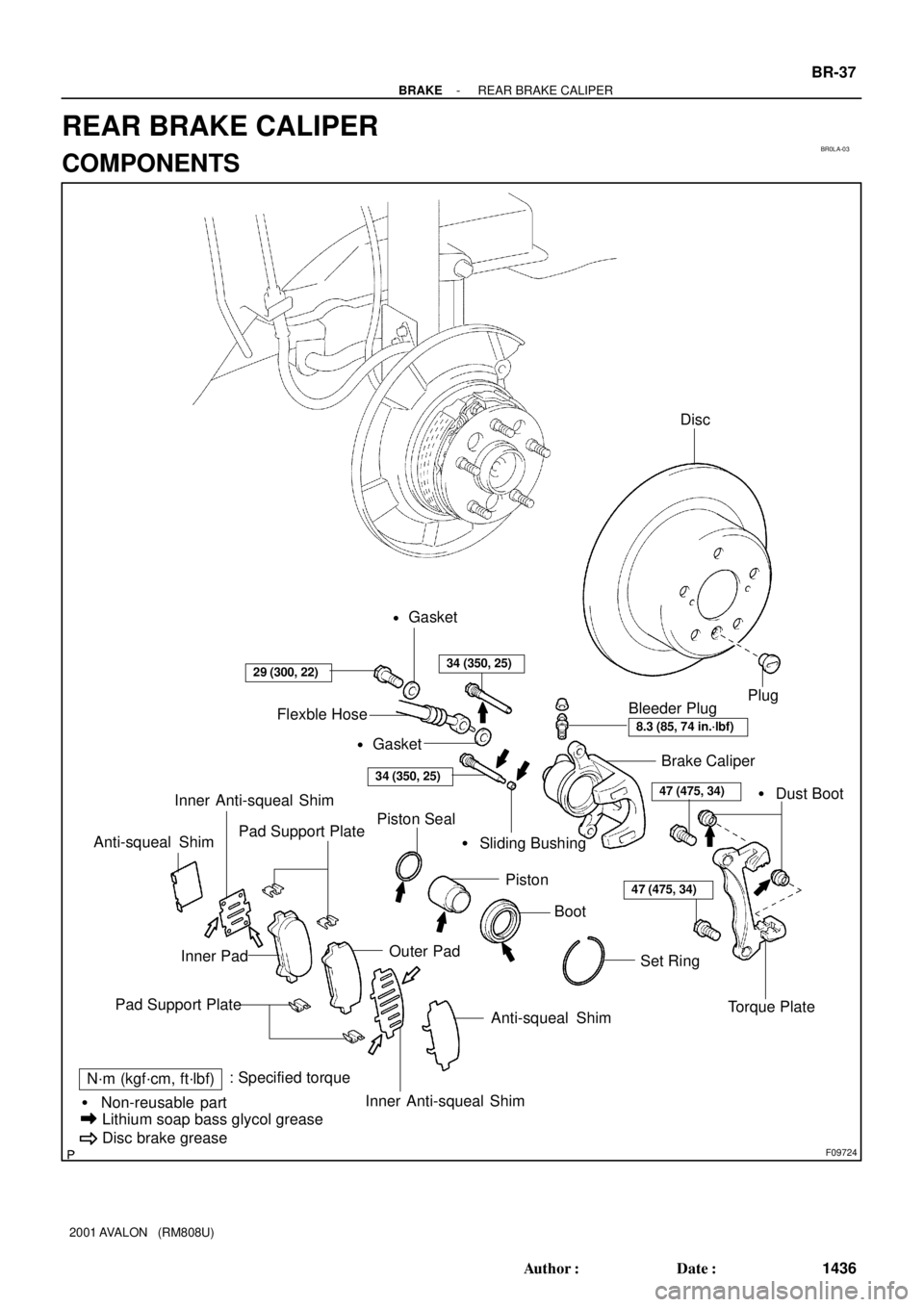
Brake Caliper
Torque Plate Piston Seal
Set Ring Piston� Dust Boot
Pad Support Plate� Sliding Bushing
Inner Pad
Anti-squeal Shim
N´m (kgf´cm, ft´lbf): Specified torque
� Non-reusable part
Lithium soap bass glycol grease
Disc brake grease
Bleeder Plug
29 (300, 22)
8.3 (85, 74 in.´lbf)
47 (475, 34)
Inner Anti-squeal Shim Anti-squeal Shim
Plug
47 (475, 34)
Boot
Pad Support Plate
Outer Pad
Inner Anti-squeal Shim
34 (350, 25)
34 (350, 25)
Flexble Hose
Disc
Gasket
�
Gasket
�
- BRAKEREAR BRAKE CALIPER
BR-37
1436 Author�: Date�:
2001 AVALON (RM808U)
REAR BRAKE CALIPER
COMPONENTS
Page 536 of 1897
BR153-01
F09726
F09727
F09728
- BRAKEREAR BRAKE CALIPER
BR-39
1438 Author�: Date�:
2001 AVALON (RM808U)
DISASSEMBLY
1. REMOVE CYLINDER BOOT SET RING AND CYL-
INDER BOOT
Using a screwdriver, remove the cylinder boot set ring and cylin-
der boot from the cylinder.
2. REMOVE PISTON
(a) Place a piece of cloth or similar, between the piston and
caliper.
(b) Use compressed air to remove the piston from the cylin-
der.
CAUTION:
Do not place your fingers in front of the piston when using
compressed air.
3. REMOVE PISTON SEAL
Using a screwdriver, remove the piston seal from the cylinder.
4. REMOVE 2 DUST BOOTS
Page 537 of 1897
BR0LD-03
F09729
BR-40
- BRAKEREAR BRAKE CALIPER
1439 Author�: Date�:
2001 AVALON (RM808U)
INSPECTION
1. MEASURE PAD LINING THICKNESS (See page
BR-31)
Standard thickness: 10.0 mm (0.394 in.)
Minimum thickness: 1.0 mm (0.039 in.)
2. MEASURE DISC THICKNESS
(See step 2 on page BR-31)
Standard thickness: 12.0 mm (0.472 in.)
Minimum thickness: 10.5 mm (0.413 in.)
3. MEASURE DISC RUNOUT
(See step 3 on page BR-31)
Maximum disc runout: 0.15 mm (0.0059 in.)
If the disc's runout is at the maximum value or greater, check the
bearing play in the axial direction and check the axle hub runout
(See page SA-45). If the bearing play and axle hub runout are
not abnormal, adjusting the disc runout or grind it on a ºOn-Carº
brake lathe.
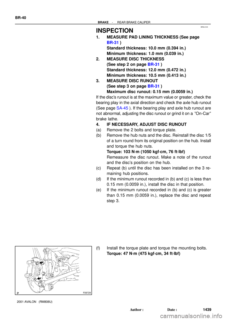
4. IF NECESSARY, ADJUST DISC RUNOUT
(a) Remove the 2 bolts and torque plate.
(b) Remove the hub nuts and the disc. Reinstall the disc 1/5
of a turn round from its original position on the hub. Install
and torque the hub nuts.
Torque: 103 N´m (1050 kgf´cm, 76 ft´lbf)
Remeasure the disc runout. Make a note of the runout
and the disc's position on the hub.
(c) Repeat (b) until the disc has been installed on the 3 re-
maining hub positions.
(d) If the minimum runout recorded in (b) and (c) is less than
0.15 mm (0.0059 in.), install the disc in that position.
(e) If the minimum runout recorded in (b) and (c) is greater
than 0.15 mm (0.0059 in.), replace the disc and repeat
step 3.
(f) Install the torque plate and torque the mounting bolts.
Torque: 47 N´m (475 kgf´cm, 34 ft´lbf)
Page 538 of 1897
BR0LF-03
BR-42
- BRAKEREAR BRAKE CALIPER
1441 Author�: Date�:
2001 AVALON (RM808U)
INSTALLATION
Installation is in the reverse order of removal (See page BR-38).
HINT:
�After installation, fill the brake reservoir with brake fluid, bleed brake system (See page BR-4).
�Check for fluid leaks.
Page 539 of 1897
BR0LE-01
- BRAKEREAR BRAKE CALIPER
BR-41
1440 Author�: Date�:
2001 AVALON (RM808U)
REASSEMBLY
Reassembly is in the reverse order of disassembly (See page BR-39).
NOTICE:
Apply lithium soap base glycol grease to the parts indicated by the arrows (See page BR-37).
Page 540 of 1897

BR0LB-02
F09725
BR-38
- BRAKEREAR BRAKE CALIPER
1437 Author�: Date�:
2001 AVALON (RM808U)
REMOVAL
1. REMOVE REAR WHEEL
Remove the wheel and temporarily fasten the disc with hub
nuts.
Torque: 103 N´m (1,050 kgf´cm, 76 ft´lbf)
2. DISCONNECT FLEXIBLE HOSE
(a) Remove the union bolt and 2 gaskets from the caliper,
then disconnect the flexible hose from the caliper.
Torque: 29 N´m (300 kgf´cm, 22 ft´lbf)
HINT:
At the time of installation, insert the flexible hose lock securely
in the lock hole in the caliper.
(b) Use a container to catch the brake fluid as it drains out.
3. REMOVE CALIPER
(a) Remove the 2 installation bolts.
Torque: 34 N´m (350 kgf´cm, 25 ft´lbf)
NOTICE:
At the time of installation, insert the sliding pin with sliding
bushing into the bottom side.
(b) Remove the caliper from the torque plate.
4. REMOVE 2 BRAKE PADS WITH ANTI- SQUEAL
SHIMS
5. REMOVE 4 PAD SUPPORT PLATES
NOTICE:
There should be no oil or grease adhering to the friction
surfaces of the pads or disc.