2001 SUZUKI GRAND VITARA diagram
[x] Cancel search: diagramPage 443 of 656

7B1-34 AUTOMATIC TRANSMISSION (4 A/T)
DTC P0743 (DTC NO.65/66) - TCC (Lock-Up) Solenoid Electrical
WIRING DIAGRAM
DTC DETECTING CONDITION AND TROUBLE AREA
1. PCM
2. Shift solenoid-A
3. Shift solenoid-B
4. TCC solenoid
DTC DETECTING CONDITION TROUBLE AREA
Voltage at terminal C51-1-8 of PCM is high while TCC
solenoid OFF is commanded or low while TCC sole-
noid ON is commanded.•TCC (lock-up) solenoid valve
•TCC (lock-up) solenoid valve circuit
•PCM
Page 445 of 656

7B1-36 AUTOMATIC TRANSMISSION (4 A/T)
DTC P0753 (DTC NO.61/62) Shift Solenoid-A (#1) Electrical
DTC P0758 (DTC NO.63/64) Shift Solenoid-B (#2) Electrical
WIRING DIAGRAM
DTC DETECTING CONDITION AND TROUBLE AREA
1. PCM
2. Shift solenoid-A
3. Shift solenoid-B
4. TCC solenoid
DTC DETECTING CONDITION TROUBLE AREA
DTC P0753 (DTC NO.61/62):
Voltage detected at C51-1-2 terminal is specified volt-
age or lower when shift solenoid valve-A is ON or
specified voltage or higher when it is OFF.•Shift solenoid valve-A
•Shift solenoid valve-A circuit
•PCM
DTC P0758 (DTC NO.63/64):
Voltage detected at C51-1-1 terminal is specified volt-
age or lower when shift solenoid valve-B is ON or
specified voltage or higher when it is OFF.•Shift solenoid valve-B
•Shift solenoid valve-B circuit
•PCM
Page 449 of 656

7B1-40 AUTOMATIC TRANSMISSION (4 A/T)
TROUBLESHOOTING
Road Test
This test is to check if upshift and downshift take place at specified speed while actually driving vehicle on a
level road.
1) Warm up engine.
2) With engine running at idle, shift select lever “D”.
3) Accelerate vehicle speed by depressing accelerator pedal gradually.
4) While driving in “D” range, check if gear shift occurs properly as shown in “GEAR SHIFT DIAGRAM” in this
section.
TROUBLESHOOTING
Condition Possible cause
Line pressure higher than standard level in each
range•Malfunctioning regulator valve
•Malfunctioning throttle valve
•Maladjusted A/T throttle cable
Line pressure lower than standard level in each
range•Defective O/D clutch
•Defective oil pump
•Malfunctioning throttle valve
•Malfunctioning regulator value
•Maladjusted A/T throttle cable
Line pressure lower than standard level only in
“D” range•Fluid leakage from forward clutch
•Defective O/D clutch
•Leakage from “D” range fluid pressure circuit
Line pressure lower than standard level only in
“R” range•Fluid leakage from direct clutch
•Defective O/D clutch
•Fluid leakage from reverse brake
•Fluid leakage from “R” range fluid circuit
WARNING:
Carry out test in very little traffic area to prevent an accident.
Test requires 2 persons, a driver and a tester.
Condition Possible cause
When 1 → 2 upshift fails to occur 1–2 shift valve stuck
When 2 → 3 upshift fails to occur 2–3 shift valve stuck
When 3 → O/D upshift fails to occur 3–4 shift valve stuck
When gear shift point is incorrect•Maladjusted throttle cable
•Defective shift solenoid valve -A or -B
•1–2, 2–3 or 3–4 shift valve not operating properly
Page 510 of 656

BODY ELECTRICAL SYSTEM 8-1
6F1
6F2
6G
6H
6K
7A
8
6K
7C1
7D
7E
7F
8A
8D
8E
9
10
10A
10B
SECTION 8
BODY ELECTRICAL SYSTEM
Wiring System
(Harnesses, Connectors, Fuses, Relay, Switches, Grounds, System Circuit Diagram) .......... Section 8A
Lighting System .............................................................................................................................. Section 8B
Instrumententation and Driver Information .................................................................................. Section 8C
Windows, Mirrors, Security and Locks ......................................................................................... Section 8D
Immobilizer Control System............................................................................................................Section 8F
CONTENTS
General Description .......................................... 8-3
WARNING:
For vehicles equipped with Supplemental Restraint (Air Bag) System:
Service on and around the air bag system components or wiring must be performed only by an
authorized SUZUKI dealer. Refer to “Air Bag System Components and Wiring Location View” under
“General Description” in air bag system section in order to confirm whether you are performing ser-
vice on or near the air bag system components or wiring. Please observe all WARNINGS and “Ser-
vice Precautions” under “On-Vehicle Service” in air bag system section before performing service
on or around the air bag system components or wiring. Failure to follow WARNINGS could result in
unintentional activation of the system or could render the system inoperative. Either of these two
conditions may result in severe injury.
Technical service work must be started at least 90 seconds after the ignition switch is turned to the
“LOCK” position and the negative cable is disconnected from the battery. Otherwise, the system
may be activated by reserve energy in the Sensing and Diagnostic Module (SDM).
NOTE:
For the descriptions (items) not found in this section, refer to the same section of the Service Manual
mentioned in FOREWORD of this manual.
Page 522 of 656

CRUISE CONTROL SYSTEM 8E-1
6F1
6F2
6G
6H
6K
7A
7A1
7B1
7C1
7D
7E
8E
8A
8B
8C
8D
8B
9
10
10A
10B
SECTION 8E
CRUISE CONTROL SYSTEM
CONTENTS
General Description ....................................... 8E-2
Cautions in Servicing ................................... 8E-2
Symbols and Marks ...................................... 8E-2
Abbreviations ............................................... 8E-2
Wiring Color Symbols ................................... 8E-2
Joint Connector ............................................ 8E-2
Fuse Box and Relay ..................................... 8E-2
Power Supply Diagram ................................ 8E-2
Cruise Control System ................................. 8E-3
Cruise control system circuit .................... 8E-3
Components and functions....................... 8E-4
Cancel Conditions .................................... 8E-5
Diagnosis ........................................................ 8E-5
Diagnosis Table ........................................... 8E-5
Note on System Circuit Inspection ............... 8E-7
Cruise Main Switch Indicator Lamp
Circuit Check ................................................ 8E-8
“Cruise” Indicator Lamp Circuit Check ......... 8E-9
Cruise Main Switch, Coast/Set,
Resume/Accel and Cancel Switches
Circuits Check ............................................ 8E-10
VSS Circuit Check ...................................... 8E-11
Stop Lamp Switch (with Pedal Position
Switch) Circuits Check ............................... 8E-12Transmission Range Switch Circuit Check 8E-13
Clutch Pedal Position Switch Circuit Check 8E-14
Throttle Valve Opening Signal Circuit
Check ......................................................... 8E-15
Overdrive and TCC off Command Signal
Circuit Check.............................................. 8E-16
Cruise Control Module Power and Ground
Circuits Check ............................................ 8E-16
Cruise Control Module and Its Circuit
Inspection................................................... 8E-17
Cruise Cable Play Inspection and
Adjustment ................................................. 8E-19
On-Vehicle Service ...................................... 8E-19
Cruise Main Switch .................................... 8E-19
Coast/Set, Resume/Accel and Cancel
Switches..................................................... 8E-20
Vehicle Speed Sensor (VSS) ..................... 8E-20
Transmission Range Switch ...................... 8E-20
Clutch Pedal Position (CPP) Switch .......... 8E-21
Stop Lamp Switch (with Pedal Position
Switch) ....................................................... 8E-22
Cruise Control Actuator Assembly
(with Control Module) ................................. 8E-23
Cruise Cable .............................................. 8E-24
WARNING:
For vehicles equipped with Supplemental Restraint (Air Bag) System:
Service on and around the air bag system components or wiring must be performed only by an
authorized SUZUKI dealer. Refer to “Air Bag System Components and Wiring Location View” under
“General Description” in air bag system section in order to confirm whether you are performing ser-
vice on or near the air bag system components or wiring. Please observe all WARNINGS and “Ser-
vice Precautions” under “On-Vehicle Service” in air bag system section before performing service
on or around the air bag system components or wiring. Failure to follow WARNINGS could result in
unintentional activation of the system or could render the system inoperative. Either of these two
conditions may result in severe injury.
Technical service work must be started at least 90 seconds after the ignition switch is turned to the
“LOCK” position and the negative cable is disconnected from the battery. Otherwise, the system
may be activated by reserve energy in the Sensing and Diagnostic Module (SDM).
Page 523 of 656

8E-2 CRUISE CONTROL SYSTEM
General Description
Cautions in Servicing
Refer to Section 8.
Symbols and Marks
Refer to Section 8A.
Abbreviations
Refer to Section 8A.
Wiring Color Symbols
Refer to Section 8.
Joint Connector
Refer to Section 8.
Fuse Box and Relay
Refer to Section 8A.
Power Supply Diagram
Refer to Section 8A.
Page 578 of 656

AIR BAG SYSTEM 10B-1
10B
SECTION 10B
AIR BAG SYSTEM
CONTENTS
General Description ......................................10B-3
System Components and Wiring Location
View and Connectors .................................. 10B-4
System Wiring Diagram............................... 10B-5
Diagnosis .......................................................10B-6
Diagnostic Trouble Code (DTC) .................. 10B-6
Use of Special Tool ..................................... 10B-6
Intermittents and Poor Connections ............ 10B-8
Air Bag Diagnostic System Check............... 10B-9
Air Bag Diagnostic System Check Flow
Table ......................................................... 10B-10
DTC Check ................................................ 10B-11
DTC Clearance ......................................... 10B-12
DTC Table ................................................. 10B-14
Table A - “AIR BAG” Warning Lamp
Comes ON Steady .................................... 10B-16
Table B - “AIR BAG” Warning Lamp Does
Not Come ON ............................................ 10B-16
Table C - “AIR BAG” Warning Lamp
Flashes ...................................................... 10B-16Table D - “AIR BAG” Warning Lamp
Cannot Indicate Flashing Pattern of DTC . 10B-16
Table E - SDM Cannot Communicate
through The Serial Data Circuit................. 10B-21
DTC B1015 - Passenger Air Bag Initiator
Circuit Resistance High............................. 10B-23
DTC B1016 - Passenger Air Bag Initiator
Circuit Resistance Low ............................. 10B-23
DTC B1018 - Passenger Air Bag Initiator
Circuit Short to Ground ............................. 10B-23
DTC B1019 - Passenger Air Bag Initiator
Circuit Short to Power Circuit .................... 10B-23
DTC B1021 – Driver Air Bag Initiator
Circuit Resistance High............................. 10B-28
DTC B1022 – Driver Air Bag Initiator
Circuit Resistance Low ............................. 10B-28
DTC B1024 – Driver Air Bag Initiator
Circuit Short to Ground ............................. 10B-28
DTC B1025 – Driver Air Bag Initiator
Circuit Short to Power Circuit .................... 10B-28 WARNING:
Service on or around the air bag system components or wiring must be performed only by an
authorized SUZUKI dealer. Please observe all WARNINGS and “Service Precautions” under “On-
Vehicle Service” in this section before performing service on or around the air bag system compo-
nents or wiring. Failure to follow WARNINGS could result in unintended activation of the system or
could render the system inoperative. Either of these two conditions may result in severe injury.
The procedures in this section must be followed in the order listed to disable the air bag system
temporarily and prevent false diagnostic trouble codes from setting. Failure to follow procedures
could result in possible activation of the air bag system, personal injury or otherwise unneeded air
bag system repairs.
CAUTION:
When fasteners are removed, always reinstall them at the same location from which they were
removed. If a fastener needs to be replaced, use the correct part number fastener for that application.
If the correct part number fastener is not available, a fastener of equal size and strength (or stronger)
may be used. Fasteners that are not reused, and those requiring thread-locking compound, will be
called out. The correct torque value must be used when installing fasteners that require it. If the above
conditions are not followed, parts or system damage could result.
NOTE:
For the descriptions (items) not found in this section, refer to the same section of the Service Manual
mentioned in the FOREWORD of this manual.
Page 582 of 656

AIR BAG SYSTEM 10B-5
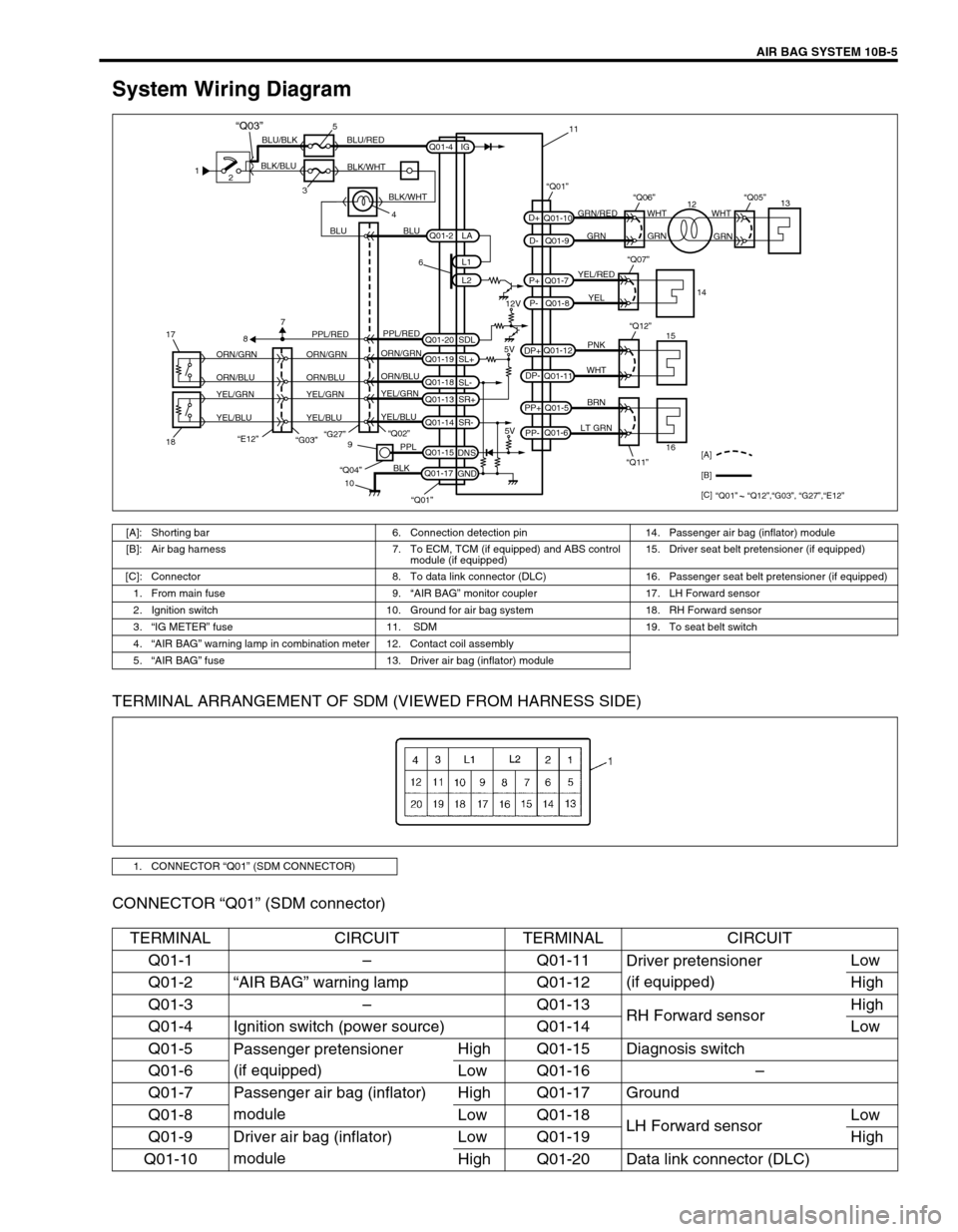
System Wiring Diagram
TERMINAL ARRANGEMENT OF SDM (VIEWED FROM HARNESS SIDE)
CONNECTOR “Q01” (SDM connector)
1
2
35
4 BLK/BLUBLU/BLK BLU/RED
BLK/WHT
BLU BLUGRN/RED
GRN GRNWHT WHT
GRN
YEL/RED
YEL
PNK
WHT
BRN
LT GRN
6
12V
5V 5V PPL/RED
ORN/GRN
ORN/BLU
YEL/GRN
YEL/BLUORN/GRN
ORN/BLU
YEL/GRN
YEL/BLUORN/GRN
ORN/BLU
YEL/GRN
YEL/BLUPPL/RED
87
“G27”
“E12”18 17“Q02”
“Q11” “Q12”9
10PPL
BLK
“Q04”
Q01-2
Q01-4
Q01-20Q01-7
Q01-8 Q01-10
Q01-9
Q01-12
Q01-11
Q01-5
Q01-6
Q01-15
Q01-17L1
L2 IG
SDL
Q01-19
SL+
Q01-18
SL-
Q01-13
SR+
Q01-14
SR-
DNS
GNDLA
PP- PP+DP- DP+P- P+D- D+
“Q07”
“Q06”“Q01”“Q05”
15
161413
12 11
[A]
[B]
[C]
“Q01” “Q12”,“G03”, “G27”,“E12”
“Q01”
BLK/WHT
“Q03”
“G03”
[A]: Shorting bar 6. Connection detection pin 14. Passenger air bag (inflator) module
[B]: Air bag harness 7. To ECM, TCM (if equipped) and ABS control
module (if equipped) 15. Driver seat belt pretensioner (if equipped)
[C]: Connector 8. To data link connector (DLC) 16. Passenger seat belt pretensioner (if equipped)
1. From main fuse 9.“AIR BAG” monitor coupler 17. LH Forward sensor
2. Ignition switch 10. Ground for air bag system 18. RH Forward sensor
3.“IG METER” fuse 11. SDM 19. To seat belt switch
4.“AIR BAG” warning lamp in combination meter 12. Contact coil assembly
5.“AIR BAG” fuse 13. Driver air bag (inflator) module
1. CONNECTOR “Q01” (SDM CONNECTOR)
TERMINAL CIRCUIT TERMINAL CIRCUIT
Q01-1–Q01-11
Driver pretensioner
(if equipped)Low
Q01-2“AIR BAG” warning lamp Q01-12 High
Q01-3–Q01-13
RH Forward sensorHigh
Q01-4 Ignition switch (power source) Q01-14 Low
Q01-5
Passenger pretensioner
(if equipped)High Q01-15 Diagnosis switch
Q01-6 Low Q01-16–
Q01-7 Passenger air bag (inflator)
moduleHigh Q01-17 Ground
Q01-8 Low Q01-18
LH Forward sensorLow
Q01-9 Driver air bag (inflator)
moduleLow Q01-19 High
Q01-10 High Q01-20 Data link connector (DLC)