2001 SUZUKI GRAND VITARA Under engine
[x] Cancel search: Under enginePage 219 of 656

6-1-58 ENGINE GENERAL INFORMATION AND DIAGNOSIS (H27 ENGINE)
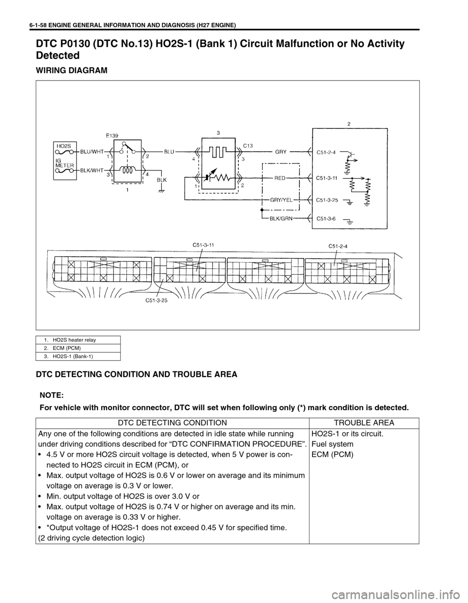
DTC P0130 (DTC No.13) HO2S-1 (Bank 1) Circuit Malfunction or No Activity
Detected
WIRING DIAGRAM
DTC DETECTING CONDITION AND TROUBLE AREA
1. HO2S heater relay
2. ECM (PCM)
3. HO2S-1 (Bank-1)
NOTE:
For vehicle with monitor connector, DTC will set when following only (*) mark condition is detected.
DTC DETECTING CONDITION TROUBLE AREA
Any one of the following conditions are detected in idle state while running
under driving conditions described for “DTC CONFIRMATION PROCEDURE”.
• 4.5 V or more HO2S circuit voltage is detected, when 5 V power is con-
nected to HO2S circuit in ECM (PCM), or
• Max. output voltage of HO2S is 0.6 V or lower on average and its minimum
voltage on average is 0.3 V or lower.
• Min. output voltage of HO2S is over 3.0 V or
• Max. output voltage of HO2S is 0.74 V or higher on average and its min.
voltage on average is 0.33 V or higher.
• *Output voltage of HO2S-1 does not exceed 0.45 V for specified time.
(2 driving cycle detection logic)HO2S-1 or its circuit.
Fuel system
ECM (PCM)
Page 221 of 656

6-1-60 ENGINE GENERAL INFORMATION AND DIAGNOSIS (H27 ENGINE)
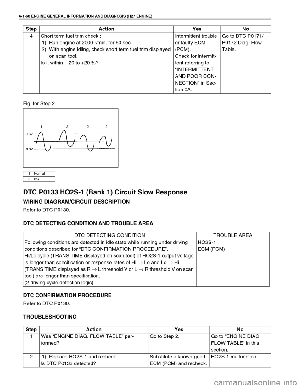
Fig. for Step 2
DTC P0133 HO2S-1 (Bank 1) Circuit Slow Response
WIRING DIAGRAM/CIRCUIT DESCRIPTION
Refer to DTC P0130.
DTC DETECTING CONDITION AND TROUBLE AREA
DTC CONFIRMATION PROCEDURE
Refer to DTC P0130.
TROUBLESHOOTING
4 Short term fuel trim check :
1) Run engine at 2000 r/min. for 60 sec.
2) With engine idling, check short term fuel trim displayed
on scan tool.
Is it within – 20 to +20 %?Intermittent trouble
or faulty ECM
(PCM).
Check for intermit-
tent referring to
“INTERMITTENT
AND POOR CON-
NECTION” in Sec-
tion 0A.Go to DTC P0171/
P0172 Diag. Flow
Table. Step Action Yes No
1. Normal
2. NG
DTC DETECTING CONDITION TROUBLE AREA
Following conditions are detected in idle state while running under driving
conditions described for “DTC CONFIRMATION PROCEDURE”.
Hi/Lo cycle (TRANS TIME displayed on scan tool) of HO2S-1 output voltage
is longer than specification or response rates of Hi → Lo and Lo → Hi
(TRANS TIME displayed as R → L threshold V or L → R threshold V on scan
tool) are longer than specification.
(2 driving cycle detection logic)HO2S-1
ECM (PCM)
Step Action Yes No
1 Was “ENGINE DIAG. FLOW TABLE” per-
formed?Go to Step 2. Go to “ENGINE DIAG.
FLOW TABLE” in this
section.
2 1) Replace HO2S-1 and recheck.
Is DTC P0133 detected?Substitute a known-good
ECM (PCM) and recheck.HO2S-1 malfunction.
Page 228 of 656

ENGINE GENERAL INFORMATION AND DIAGNOSIS (H27 ENGINE) 6-1-67
DTC P0150 (DTC No.26) HO2S-1 (Bank 2) Circuit Malfunction or No Activity
Detected
WIRING DIAGRAM
DTC DETECTING CONDITION AND TROUBLE AREA
1. HO2S heater relay
2. ECM (PCM)
3. HO2S-1 (Bank-2)
NOTE:
For vehicle with monitor connector, DTC will set when following only (*) mark condition is detected.
DTC DETECTING CONDITION TROUBLE AREA
Any one of the following conditions are detected in idle state while running
under driving conditions described for “DTC CONFIRMATION PROCEDURE”.
• 4.5 V or more HO2S circuit voltage is detected, when 5 V power is con-
nected to HO2S circuit in ECM (PCM), or
• Max. output voltage of HO2S is 0.6 V or lower on average and its minimum
voltage on average is 0.3 V or lower.
• Min. output voltage of HO2S is over 3.0 V or
• Max. output voltage of HO2S is 0.74 V or higher on average and its min.
voltage on average is 0.33 V or higher.
• Output voltage of HO2S-1 does not exceed 0.45 V for specified time.
(2 driving cycle detection logic)HO2S-1 or its circuit.
Fuel system
ECM (PCM)
Page 230 of 656

ENGINE GENERAL INFORMATION AND DIAGNOSIS (H27 ENGINE) 6-1-69
Fig. for Step 2
DTC P0153 HO2S-1 (Bank 2) Circuit Slow Response
WIRING DIAGRAM/CIRCUIT DESCRIPTION
Refer to DTC P0150.
DTC DETECTING CONDITION AND TROUBLE AREA
DTC CONFIRMATION PROCEDURE
Refer to DTC P0150.
TROUBLESHOOTING
4 Short term fuel trim check :
1) Run engine at 2000 r/min. for 60 sec.
2) With engine idling, check short term fuel trim displayed
on scan tool.
Is it within – 20 to +20 %?Intermittent trouble
or faulty ECM
(PCM).
Check for intermit-
tent referring to
“INTERMITTENT
AND POOR CON-
NECTION” in Sec-
tion 0A.Go to DTC P0174/
P0175 Diag. Flow
Table. Step Action Yes No
1. Normal
2. NG
DTC DETECTING CONDITION TROUBLE AREA
Following conditions are detected in idle state while running under driving
conditions described for “DTC CONFIRMATION PROCEDURE”.
Hi/Lo cycle (TRANS TIME displayed on scan tool) of HO2S-1 output voltage
is longer than specification or response rates of Hi → Lo and Lo → Hi
(TRANS TIME displayed as R → L threshold V or L → R threshold V on scan
tool) are longer than specification.
(2 driving cycle detection logic)HO2S-1
ECM (PCM)
Step Action Yes No
1 Was “ENGINE DIAG. FLOW TABLE” per-
formed?Go to Step 2. Go to “ENGINE DIAG.
FLOW TABLE” in this
section.
2 1) Replace HO2S-1 and recheck.
Is DTC P0153 detected?Substitute a known-good
ECM (PCM) and recheck.HO2S-1 malfunction.
Page 255 of 656

6-1-94 ENGINE GENERAL INFORMATION AND DIAGNOSIS (H27 ENGINE)
DTC P0420 Catalyst System Efficiency Below Threshold (Bank 1)
SYSTEM DIAGRAM
CIRCUIT DESCRIPTION
Exhaust oxygen concentration at the pre-catalyst and the post-catalyst of WU-TWC is detected from HO2S-1
and HO2S-2 respectively and accordingly ECM (PCM) controls the closed loop which then controls the fuel
injection volume. (Refer to Section 6E2.) While the above control is going on and if WU-TWC is in good condi-
tion, the output voltage of HO2S-2 is maintained at specified level. As WU-TWC becomes deteriorated, even
when the above control is going on, the exhaust gas which has passed WU-TWC then passes HO2S-2 at the
exhaust oxygen concentration similar to that of the pre-catalyst without being oxygenated or converted. Thus,
waveforms of HO2S-1 and HO2S-2 output voltages become alike. ECM (PCM) judges deterioration of WU-TWC
by comparing waveforms of HO2S-1 and HO2S-2.
DTC DETECTING CONDITION AND TROUBLE AREA
1. HO2S-1 (Bank-1) 4. TWC
2. HO2S-2 (Bank-1) 5. ECM (PCM)
3. WU-TWC
DTC DETECTING CONDITION TROUBLE AREA
While running under conditions described for DTC CON-
FIRMATION PROCEDURE, output waveform of HO2S-1
becomes similar to that of HO2S-2.
(2 driving cycle detection logic)• Exhaust gas leakage
• Warm up three way catalytic converter
• Heated oxygen sensor – 2 or its circuit
•ECM (PCM)
Page 257 of 656

6-1-96 ENGINE GENERAL INFORMATION AND DIAGNOSIS (H27 ENGINE)
DTC P0430 Catalyst System Efficiency Below Threshold (Bank 2)
SYSTEM DIAGRAM
CIRCUIT DESCRIPTION
Exhaust oxygen concentration at the pre-catalyst and the post-catalyst of WU-TWC is detected from HO2S-1
and HO2S-2 respectively and accordingly ECM (PCM) controls the closed loop which then controls the fuel
injection volume. (Refer to Section 6E2.) While the above control is going on and if WU-TWC is in good condi-
tion, the output voltage of HO2S-2 is maintained at specified level. As WU-TWC becomes deteriorated, even
when the above control is going on, the exhaust gas which has passed TWC then passes HO2S-2 at the
exhaust oxygen concentration similar to that of the pre-catalyst without being oxygenated or converted. Thus,
waveforms of HO2S-1 and HO2S-2 output voltages become alike. ECM (PCM) judges deterioration of WU-TWC
by comparing waveforms of HO2S-1 and HO2S-2.
DTC DETECTING CONDITION AND TROUBLE AREA
1. HO2S-1 (Bank-2) 4. TWC
2. HO2S-2 (Bank-2) 5. ECM (PCM)
3. WU-TWC
DTC DETECTING CONDITION TROUBLE AREA
While running under conditions described for DTC CON-
FIRMATION PROCEDURE, output waveform of HO2S-1
becomes similar to that of HO2S-2.
(2 driving cycle detection logic)• Exhaust gas leakage
• Warm up three way catalytic converter
• Heated oxygen sensor – 2 or its circuit
•ECM (PCM)
Page 273 of 656

6-1-112 ENGINE GENERAL INFORMATION AND DIAGNOSIS (H27 ENGINE)
1) Connect scan tool to DLC with ignition switch OFF.
2) Turn ON ignition switch and clear DTC, pending DTC and freeze frame data by using scan tool and warm up
engine completely.
3) Run engine at idle speed for 1 min. (engine coolant temp. becomes 76°C (169°F) or more).
4) Increase vehicle speed to 80 km/h (50 mph).
5) Keep driving above vehicle speed for 1 min (Change of vehicle speed is permitted in this step).
6) Stop vehicle and check pending DTC by using scan tool.
TROUBLESHOOTING
Step Action Yes No
1Was “ENGINE DIAG. FLOW TABLE” per-
formed?Go to Step 2. Go to “ENGINE DIAG.
FLOW TABLE” in this
section.
2 MAP sensor signal check :
1) Remove ECM (PCM) cover.
2) Check voltage between C51-3-8 and C51-
3-25 under following conditions.
•With ignition switch ON leaving engine OFF
: 0.2 V or higher
•At idling : 4.6 V or lower
Is check result as specified?Intermittent trouble or
faulty ECM (PCM).
Check for intermittent
referring to “INTERMIT-
TENT AND POOR CON-
NECTION” in Section 0A.Go to Step 3.
3 MAP sensor check :
1) Disconnect connector from MAP sensor.
2) Check for proper connection to MAP sensor
at each terminal.
3) If OK, check MAP sensor for performance
referring to “MAP SENSOR INSPECTION”
in Section 6E2.
Is check result satisfactory?“RED/WHT”, “GRY/YEL”
or “GRY/RED” circuit
open/short.
If wire and connections
are OK, substitute a
known-good ECM (PCM)
and recheck.Replace MAP sensor.
Page 274 of 656

ENGINE GENERAL INFORMATION AND DIAGNOSIS (H27 ENGINE) 6-1-113
DTC P1450/P1451 Barometric Pressure Sensor Circuit Malfunction/Perfor-
mance Problem
SYSTEM DESCRIPTION
Barometric pressure sensor is installed in ECM (PCM).
DTC DETECTING CONDITION AND TROUBLE AREA
DTC CONFIRMATION PROCEDURE
For DTC P1450
1) Connect scan tool to DLC with ignition switch OFF.
2) Turn ON ignition switch and clear DTC by using scan tool and run engine for 1 min.
3) Check DTC by using scan tool.
For DTC P1451
1) Connect scan tool to DLC with ignition switch OFF.
2) Turn ON ignition switch and clear DTC, pending DTC and freeze frame data by using scan tool and warm up
engine to normal operating temperature.
3) Increase engine speed to 3,000 r/min. in 3rd gear in case of M/T and “2” range in case of A/T.
4) Release accelerator pedal and with engine brake applied, keep vehicle coasting for 5 sec. or more (keep fuel
cut condition for 5 sec. or more). If fuel cut condition is not kept for 5 sec. or more, coast down a slope in
engine speed 1600 – 3000 r/min for 5 sec. or more.
5) Stop vehicle and run engine at idle.
6) Repeat steps 3) – 5) 2 times.
7) Check pending DTC by using scan tool.
TROUBLESHOOTING (DTC P1450/P1451)
DTC DETECTING CONDITION TROUBLE AREA
DTC P1450 :
Barometric pressure out of specification is detected.•Barometric pressure sensor in ECM
(PCM)
DTC P1451 :
While running under conditions described for “DTC CONFIRMATION
PROCEDURE”, barometric pressure value compared with intake
manifold vacuum value in fuel cut state is not as specified.
(2 driving cycle detection logic)•Manifold absolute pressure sensor
performance problem
•Barometric pressure sensor in ECM
(PCM)
WARNING:
When performing a road test, select a place where there is no traffic or possibility of a traffic acci-
dent and be very careful during testing to avoid occurrence of an accident.
Road test should be carried out with 2 persons, a driver and a tester, on a level road.
Step Action Yes No
1Was “ENGINE DIAG. FLOW TABLE” performed? Go to Step 2. Go to “ENGINE DIAG. FLOW
TABLE” in this section.
2 Is DTC P1451 set? Go to Step 3. Substitute a known-good
ECM (PCM) and recheck.
3 MAP sensor check :
1) Check MAP sensor and its circuit referring to
Steps 2 and 3 of “DTC P1408 Diag. Flow Table”.
Is check result satisfactory?Substitute a
known-good
ECM (PCM) and
recheck.MAP sensor or its circuit mal-
function.